Downloaded 865 times
![EYE TRACKING INTERPRETATION SYSTEM
List of Figures
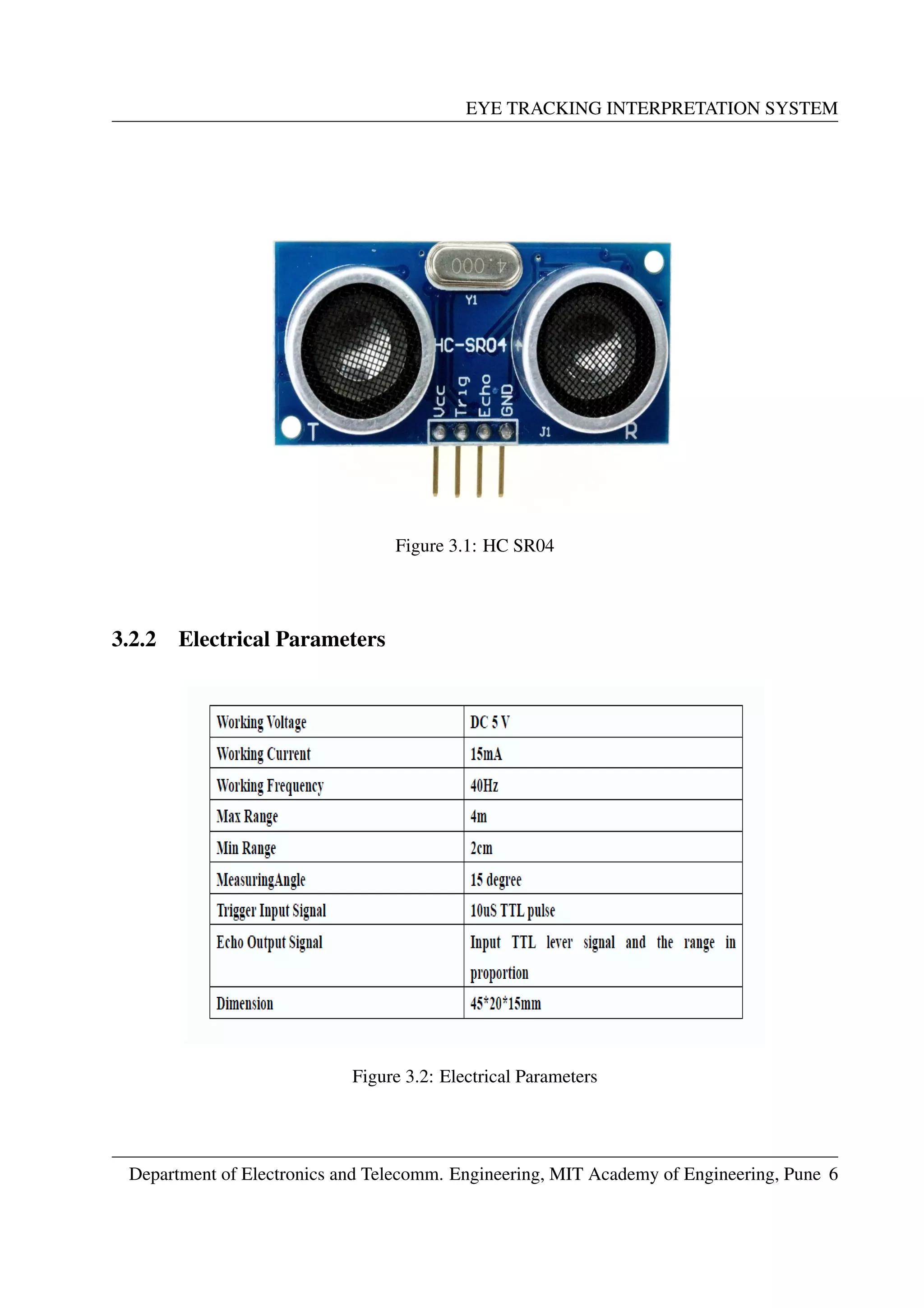
3.1 HC SR04 . . . . . . . . . . . . . . . . . . . . . . . . . . . . . . . . . . . . . . . 6
3.2 Electrical Parameters . . . . . . . . . . . . . . . . . . . . . . . . . . . . . . . . . 6
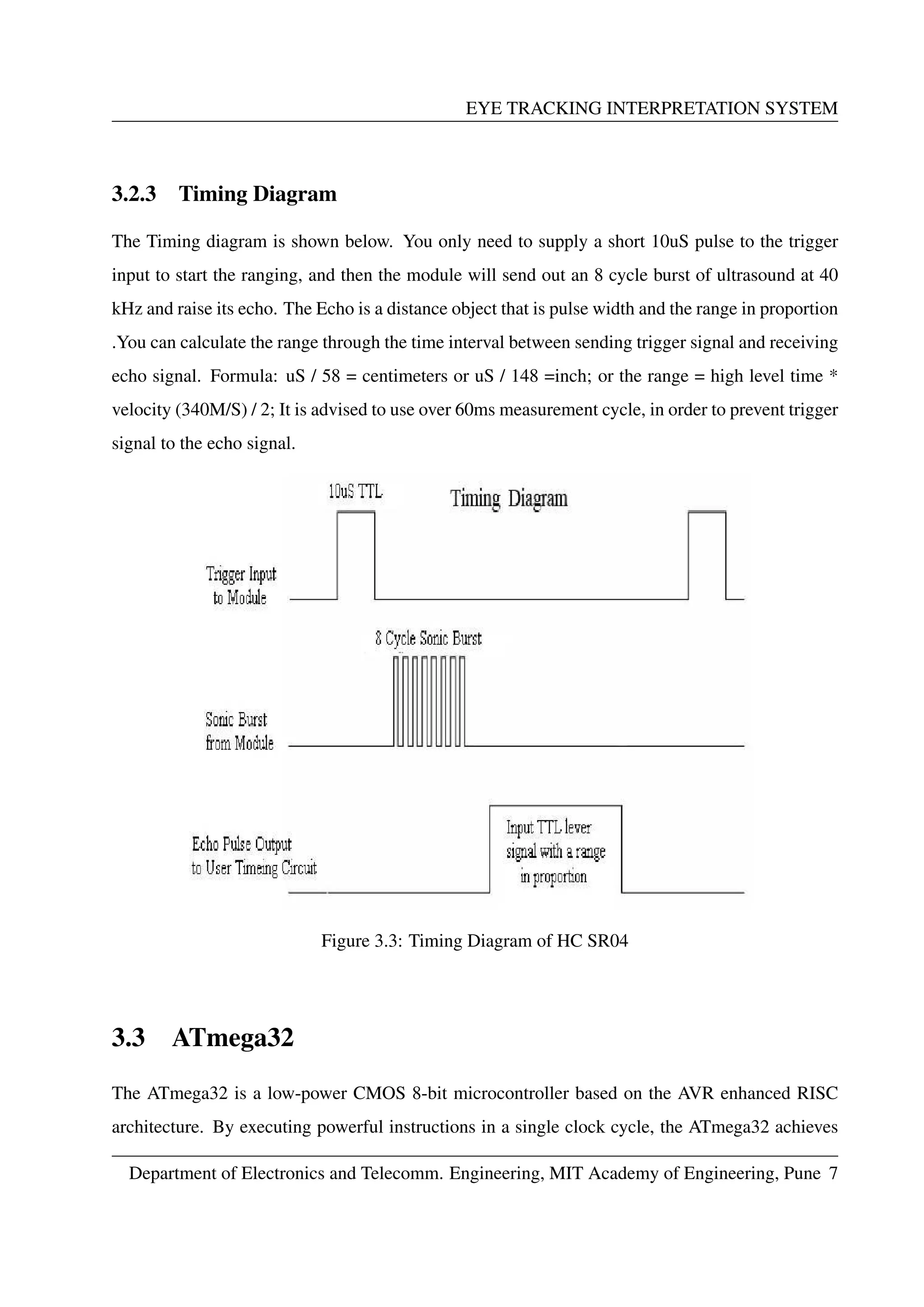
3.3 Timing Diagram of HC SR04 . . . . . . . . . . . . . . . . . . . . . . . . . . . . . 7
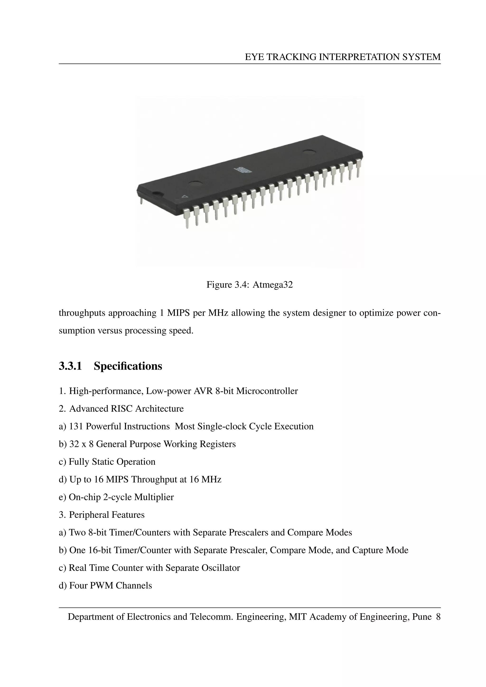
3.4 Atmega32 . . . . . . . . . . . . . . . . . . . . . . . . . . . . . . . . . . . . . . . 8
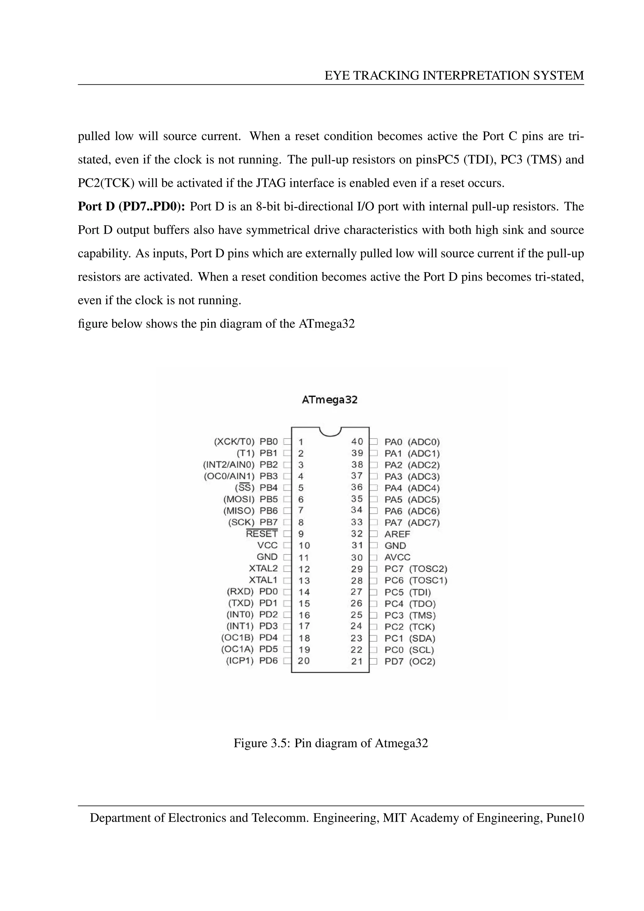
3.5 Pin diagram of Atmega32 . . . . . . . . . . . . . . . . . . . . . . . . . . . . . . . 10
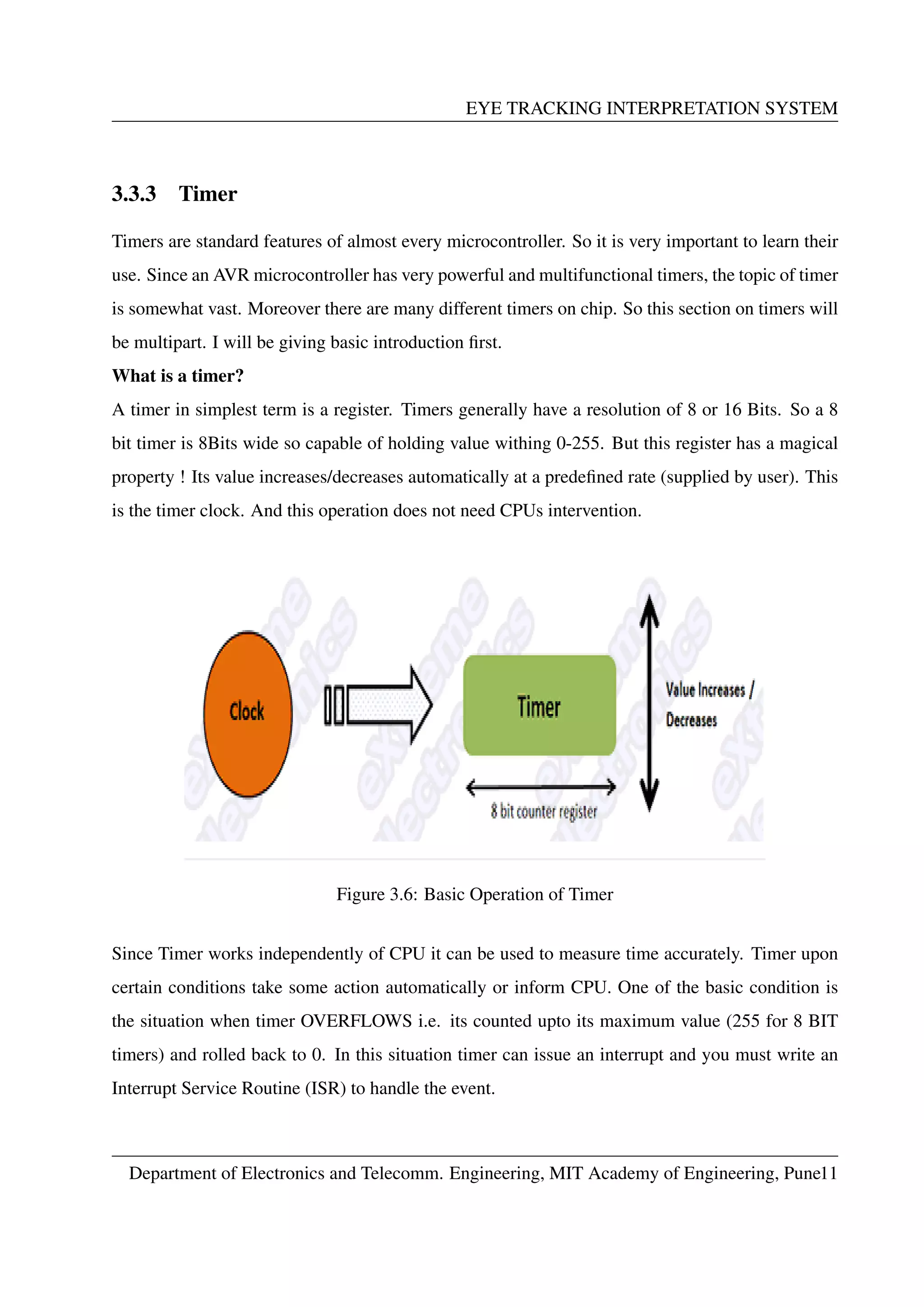
3.6 Basic Operation of Timer . . . . . . . . . . . . . . . . . . . . . . . . . . . . . . . 11
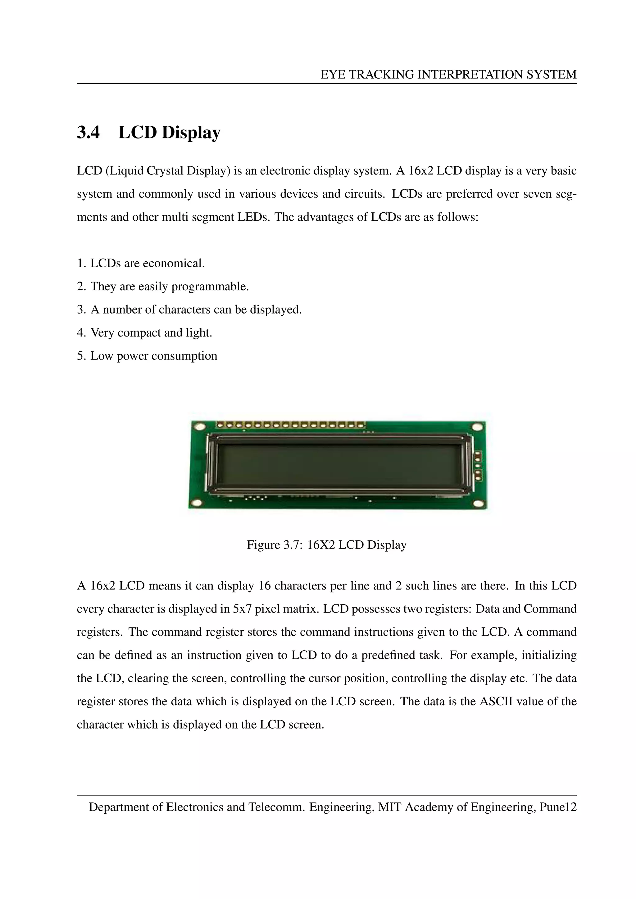
3.7 16X2 LCD Display . . . . . . . . . . . . . . . . . . . . . . . . . . . . . . . . . . 12
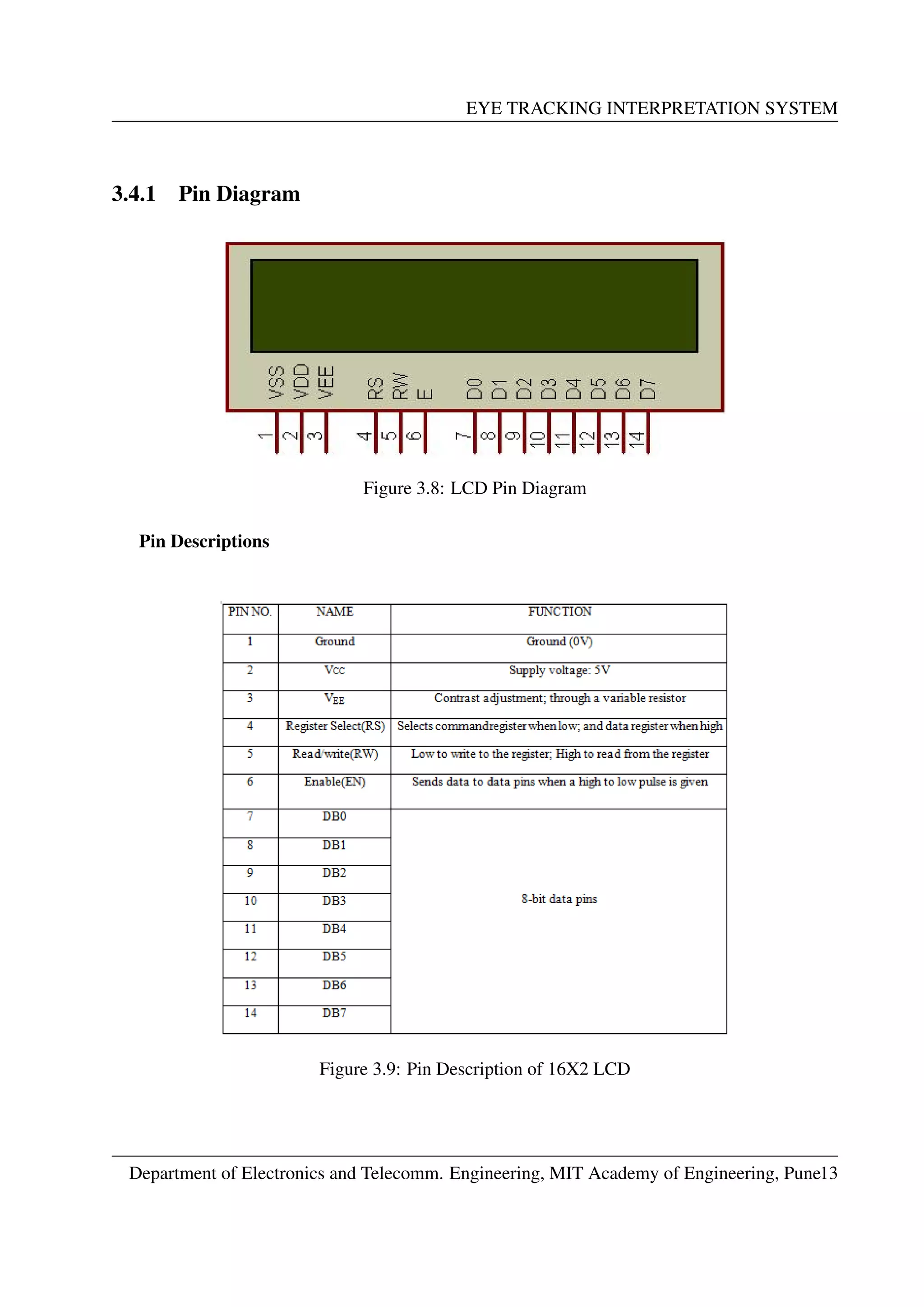
3.8 LCD Pin Diagram . . . . . . . . . . . . . . . . . . . . . . . . . . . . . . . . . . . 13
3.9 Pin Description of 16X2 LCD . . . . . . . . . . . . . . . . . . . . . . . . . . . . 13
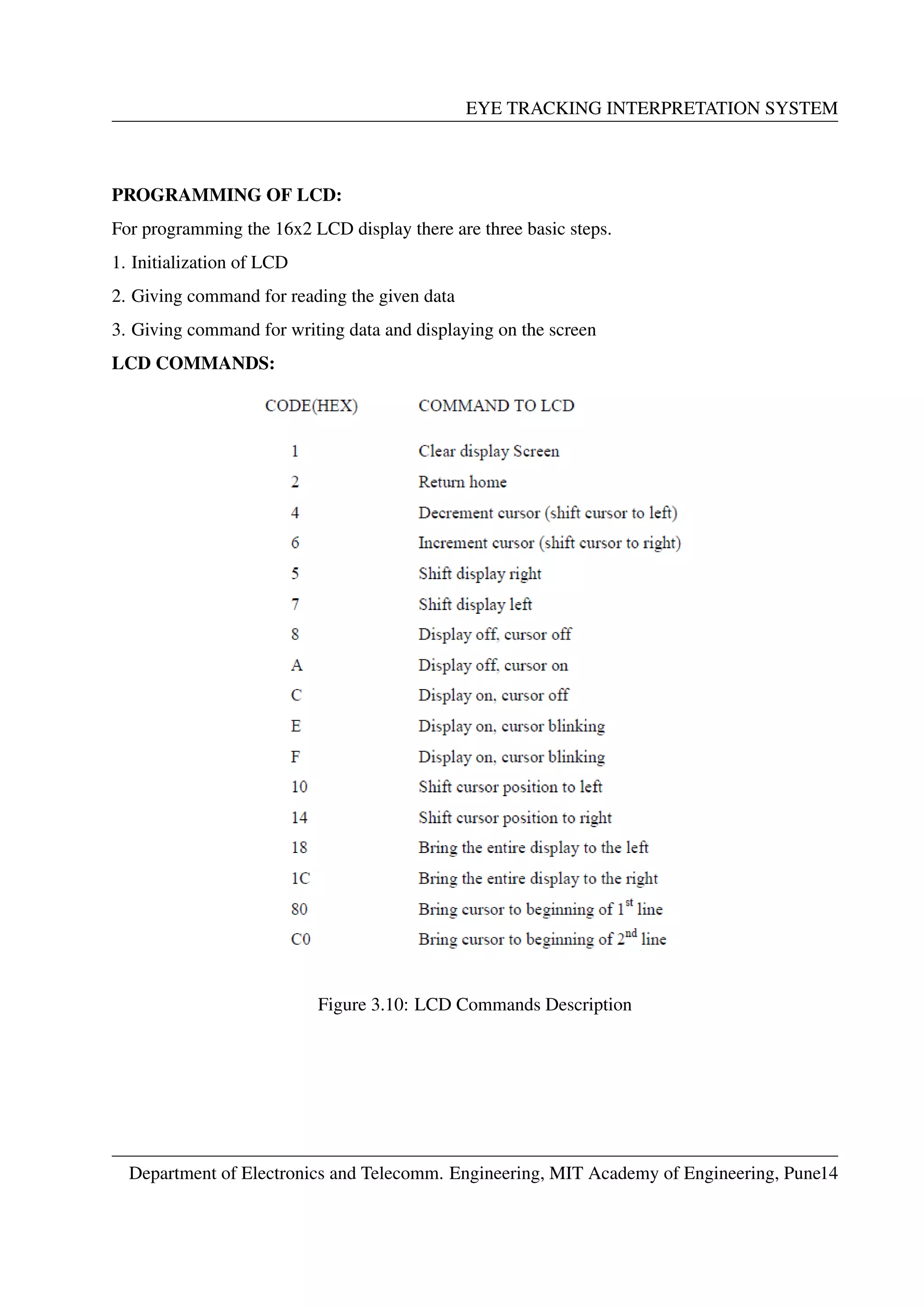
3.10 LCD Commands Description . . . . . . . . . . . . . . . . . . . . . . . . . . . . . 14
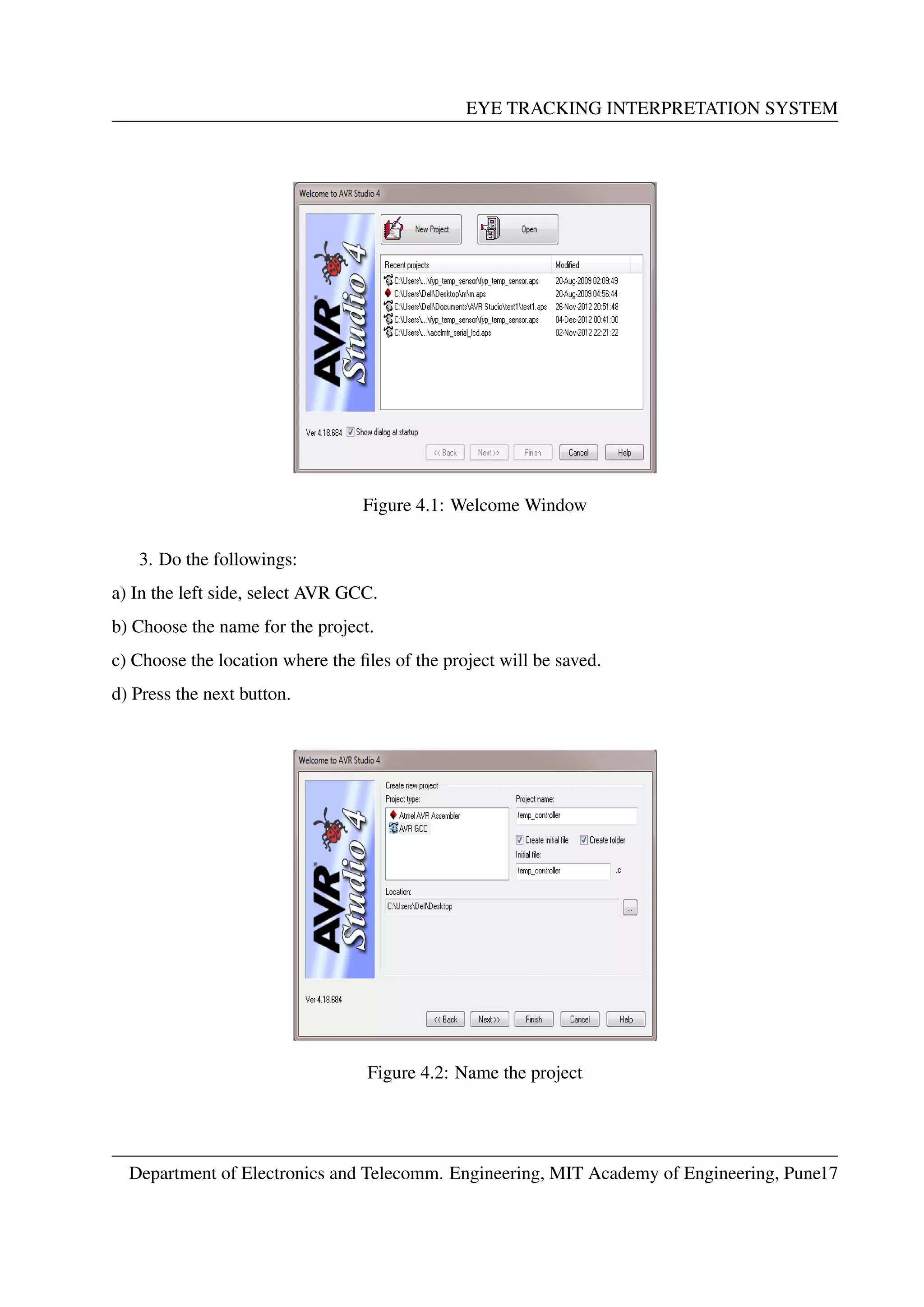
4.1 Welcome Window . . . . . . . . . . . . . . . . . . . . . . . . . . . . . . . . . . . 17
4.2 Name the project . . . . . . . . . . . . . . . . . . . . . . . . . . . . . . . . . . . 17
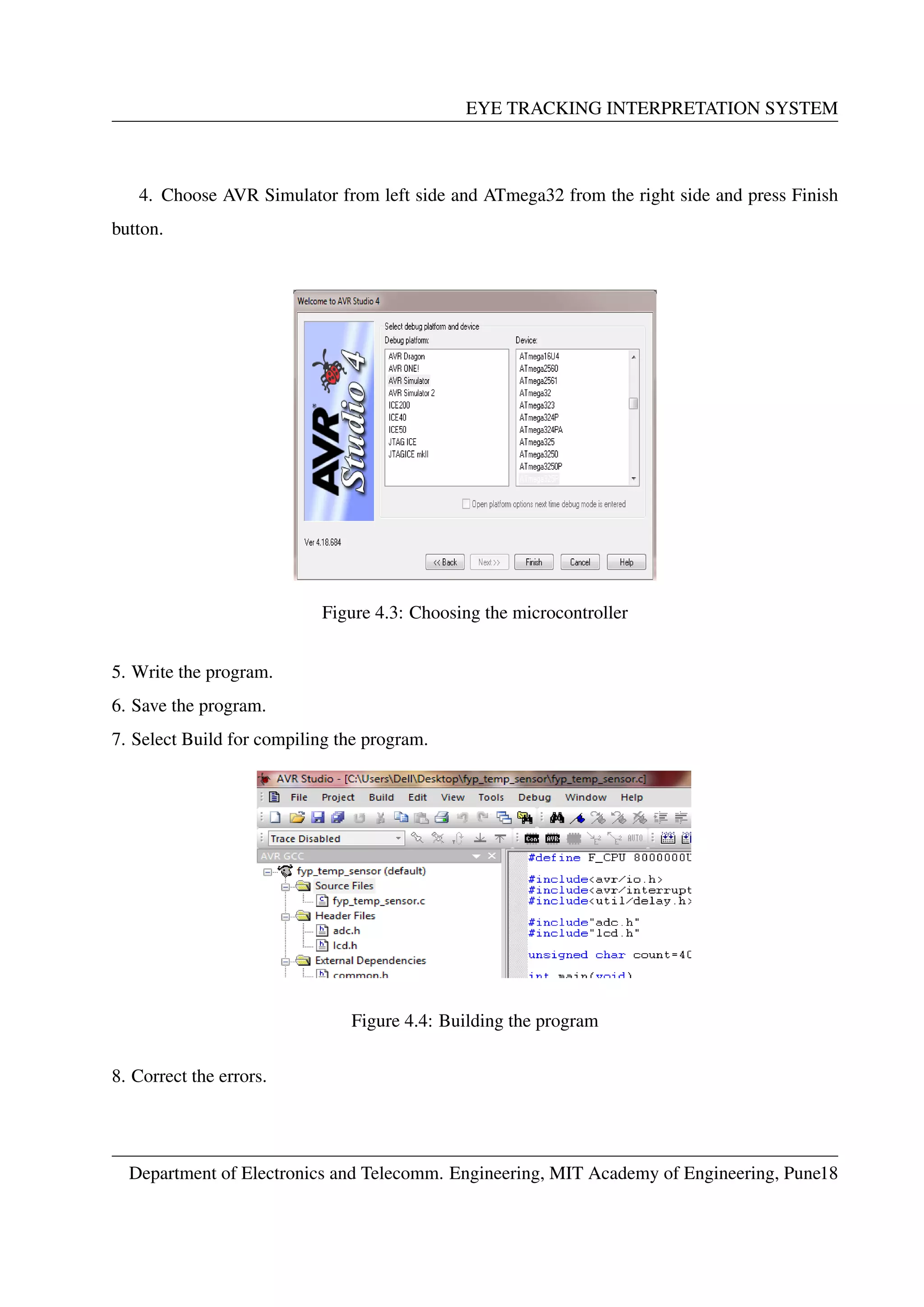
4.3 Choosing the microcontroller . . . . . . . . . . . . . . . . . . . . . . . . . . . . . 18
4.4 Building the program . . . . . . . . . . . . . . . . . . . . . . . . . . . . . . . . . 18
5.1 Block Diagram[9]
. . . . . . . . . . . . . . . . . . . . . . . . . . . . . . . . . . . 20
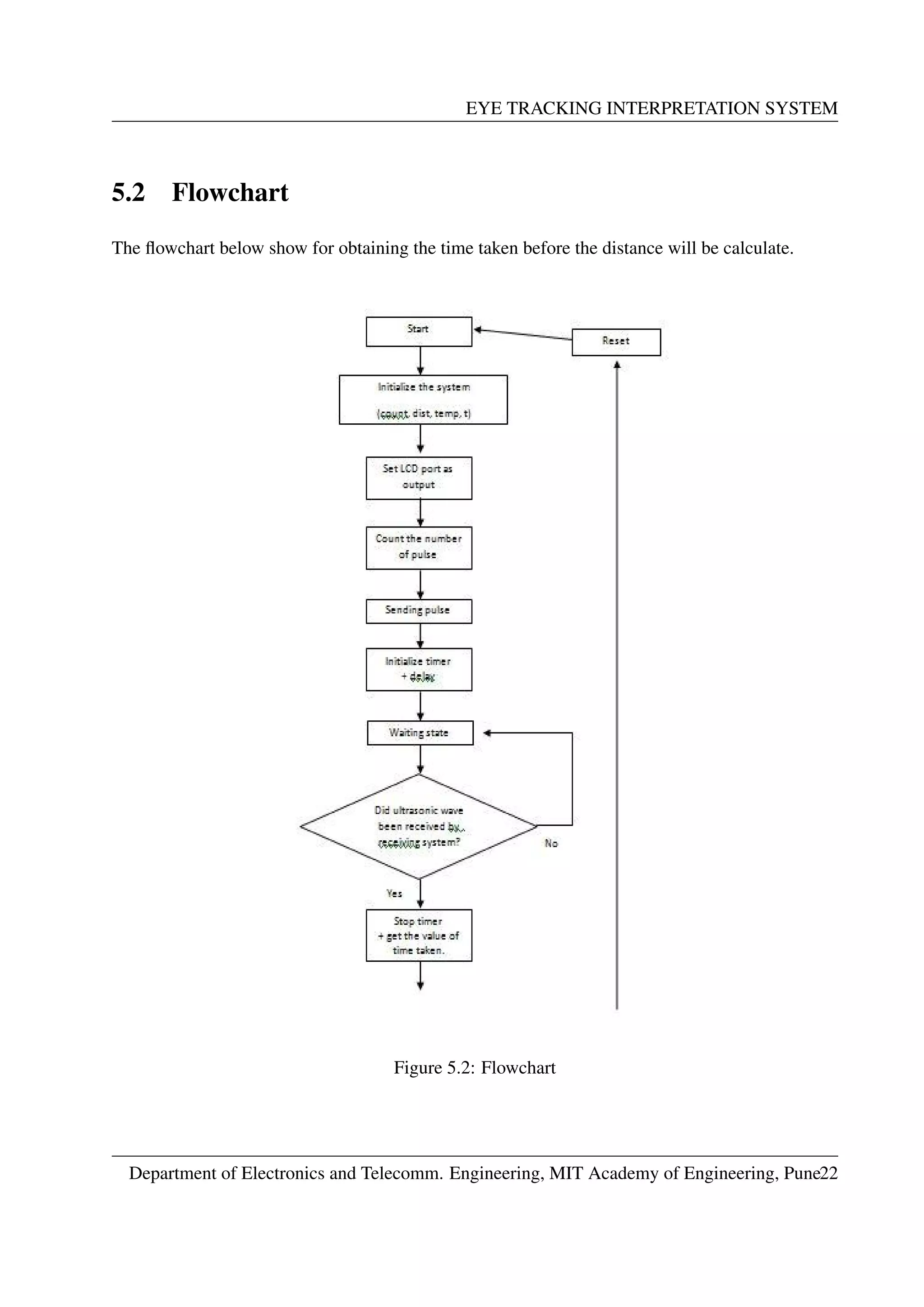
5.2 Flowchart . . . . . . . . . . . . . . . . . . . . . . . . . . . . . . . . . . . . . . . 22
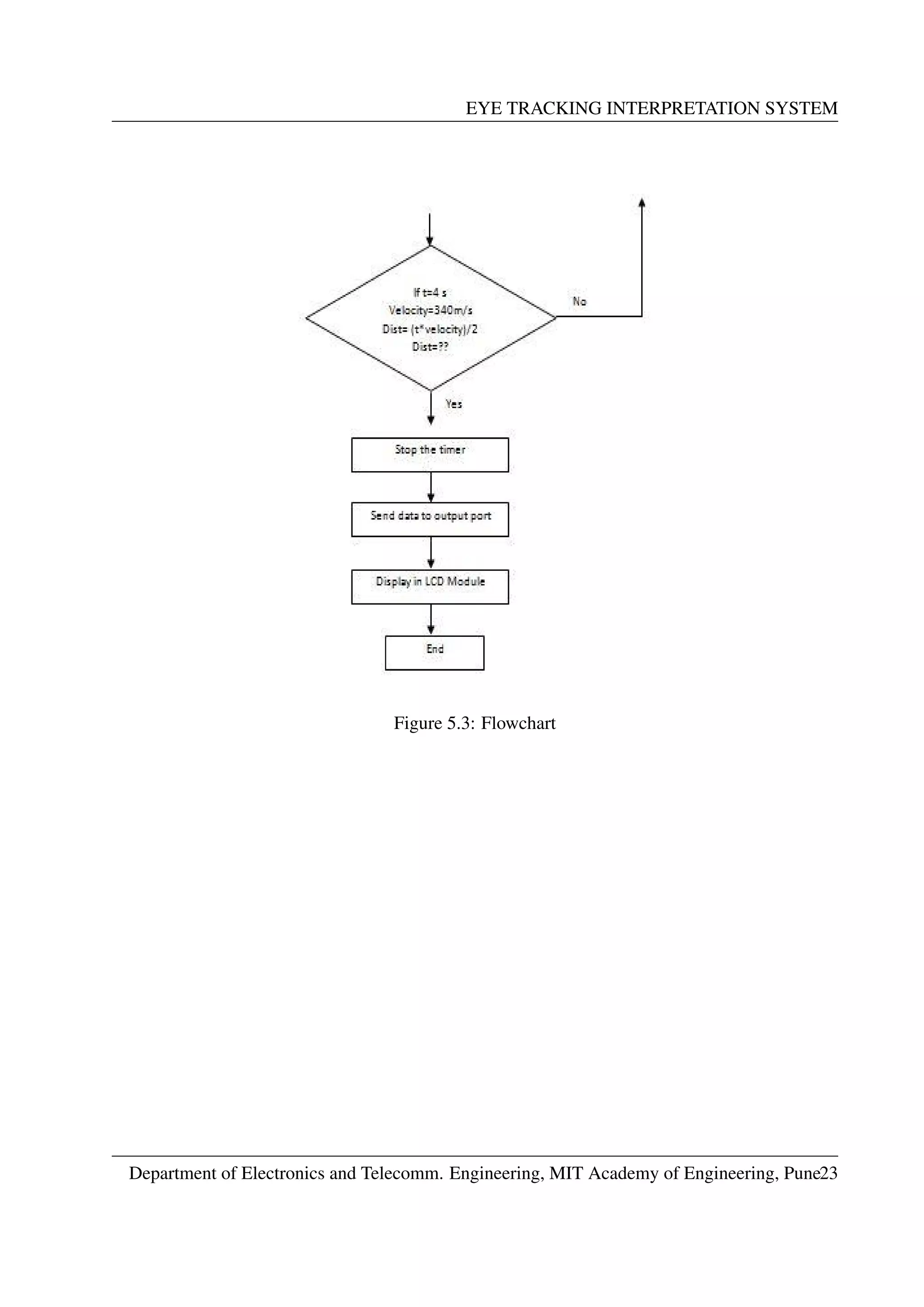
5.3 Flowchart . . . . . . . . . . . . . . . . . . . . . . . . . . . . . . . . . . . . . . . 23
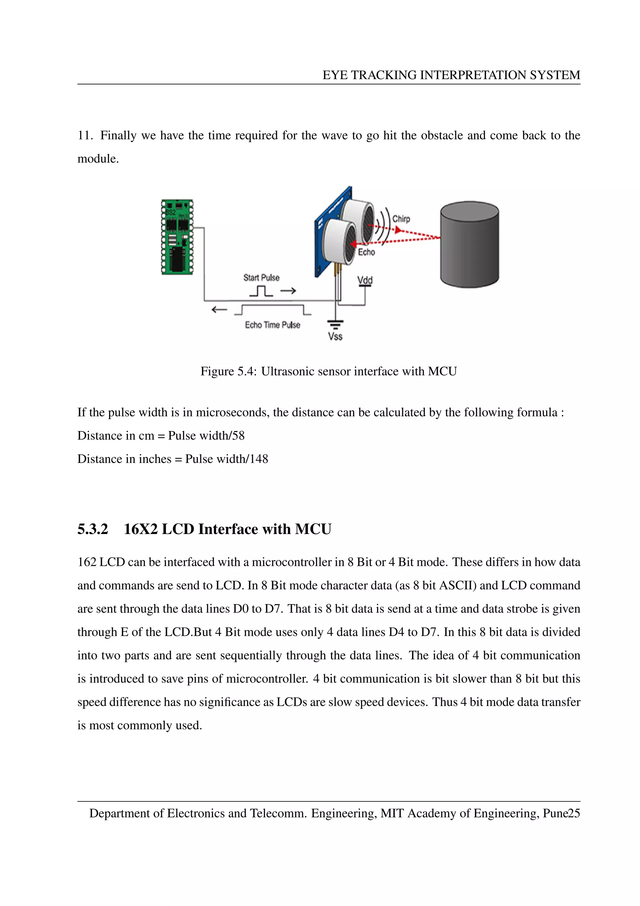
5.4 Ultrasonic sensor interface with MCU . . . . . . . . . . . . . . . . . . . . . . . . 25
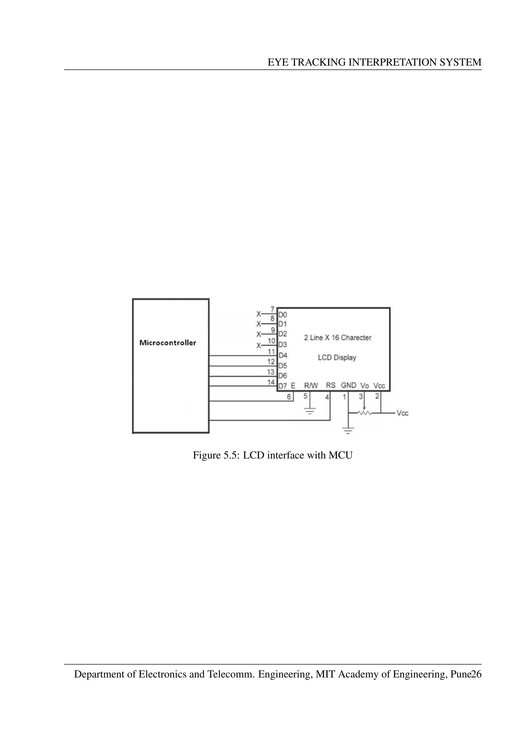
5.5 LCD interface with MCU . . . . . . . . . . . . . . . . . . . . . . . . . . . . . . . 26
Department of Electronics and Telecomm. Engineering, MIT Academy of Engineering, Puneiii](https://image.slidesharecdn.com/ac-160501050733/75/Project-Report-Distance-measurement-system-7-2048.jpg)
![EYE TRACKING INTERPRETATION SYSTEM
Chapter 5
METHODOLOGY
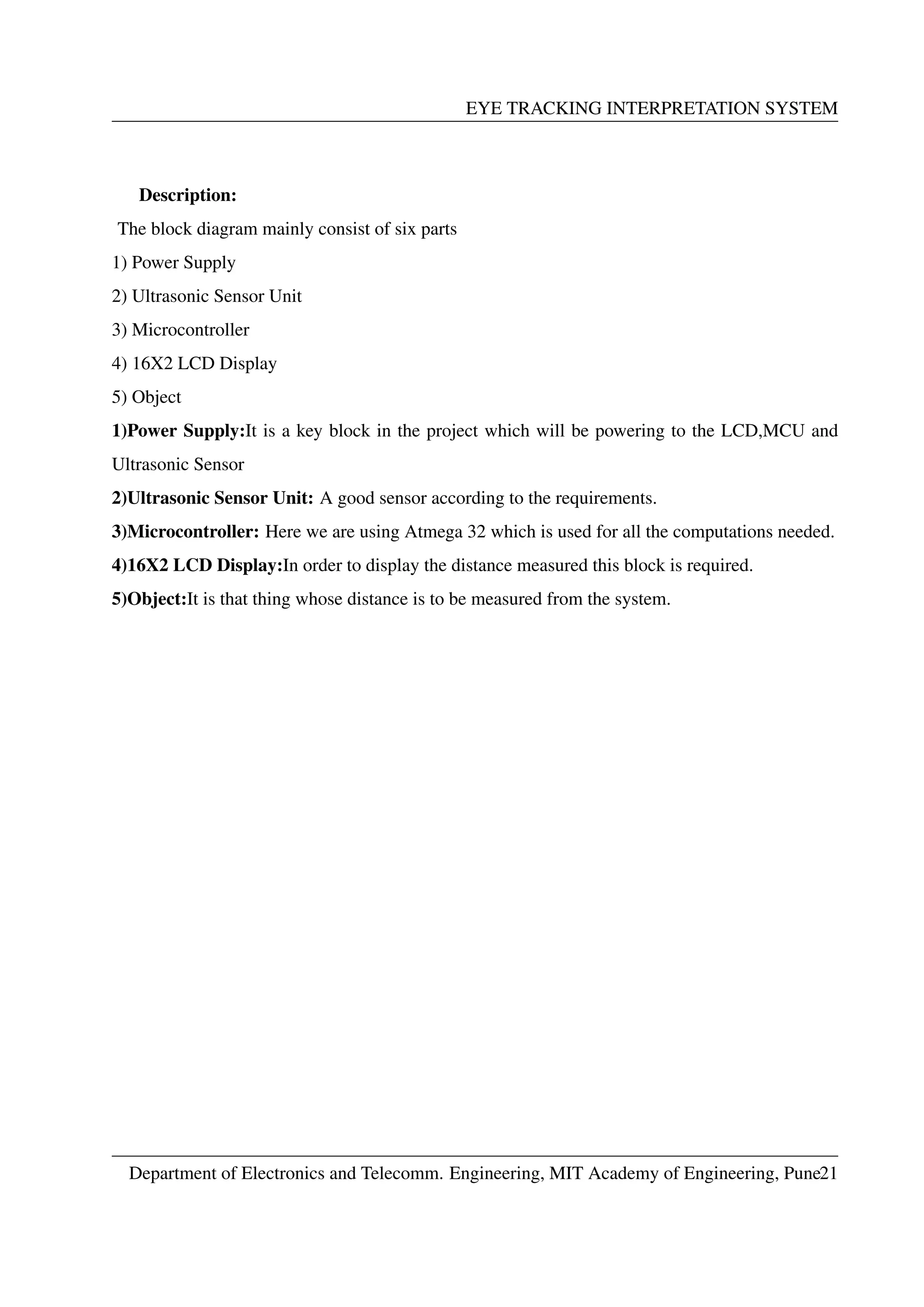
5.1 Block Diagram and Description
Block Diagram:
Figure 5.1: Block Diagram[9]
Department of Electronics and Telecomm. Engineering, MIT Academy of Engineering, Pune20](https://image.slidesharecdn.com/ac-160501050733/75/Project-Report-Distance-measurement-system-28-2048.jpg)


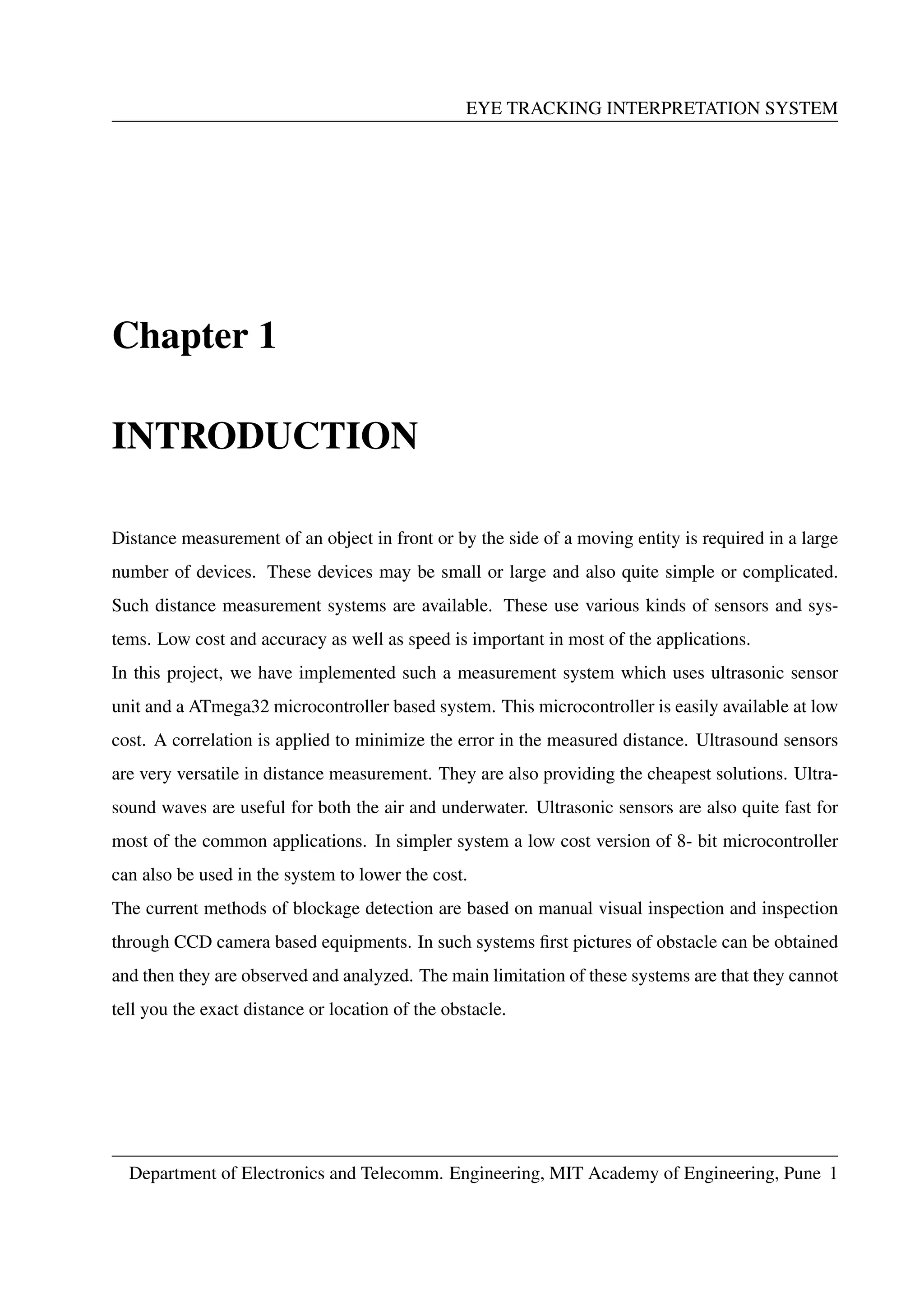
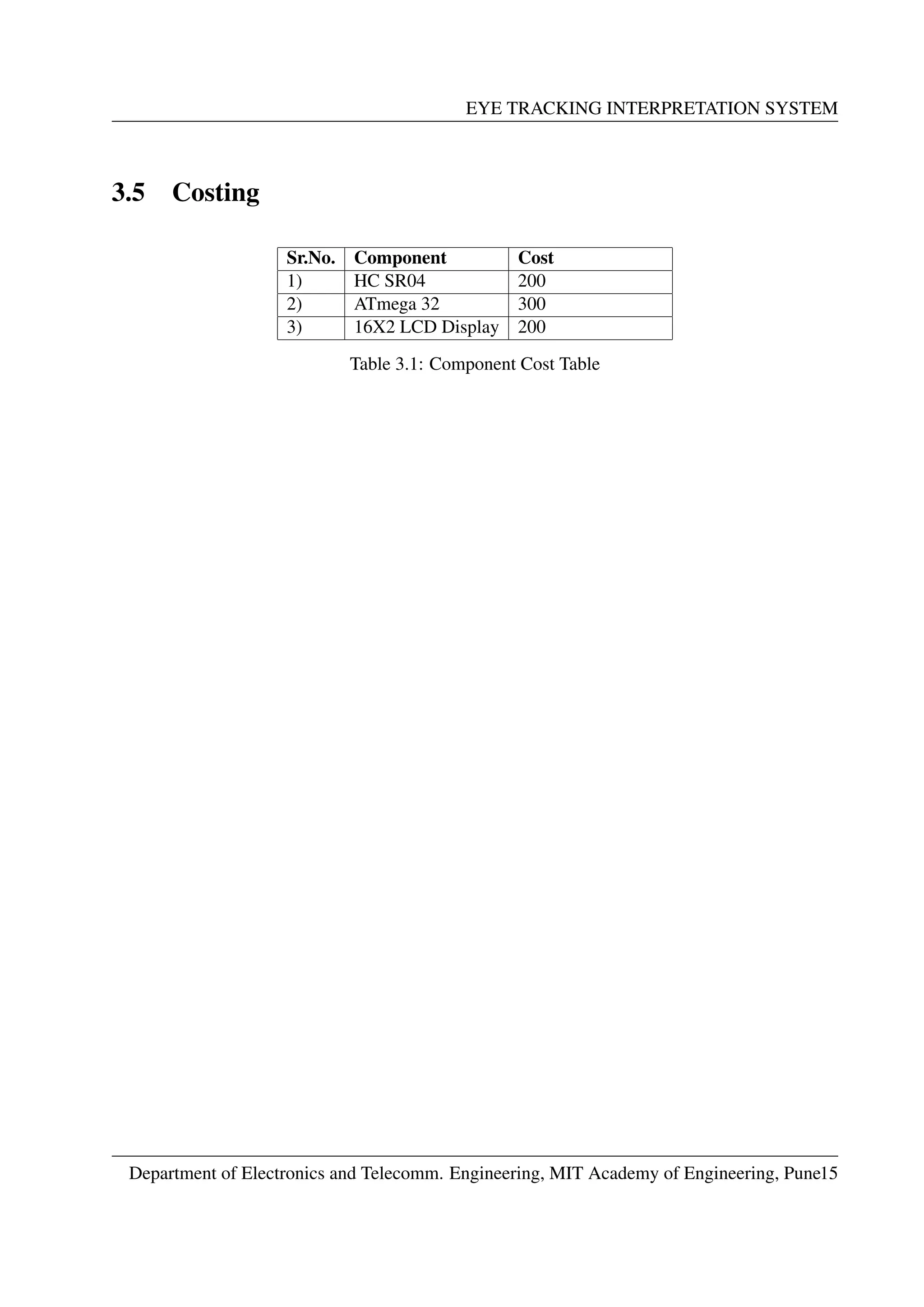
This document is a project report on an Eye Tracking Interpretation System submitted by three students as a partial fulfillment of their Bachelor of Electronics and Telecommunication Engineering degree. It includes sections on introduction, literature survey, system description, software description, methodology, results, applications, and conclusion. The system uses an ultrasonic sensor and microcontroller to measure the distance to obstacles and displays it on an LCD screen. It aims to provide a low-cost solution for distance measurement that works in different light conditions including underwater.