This document presents a particle swarm optimization-backstepping (PSO-backstepping) controller for a doubly fed induction generator (DFIG) based wind turbine system. The controller aims to maximize energy extraction and control the active and reactive power exchanged between the generator and grid despite parameter uncertainties. An artificial bee colony algorithm is used to select the optimal rotor speed to extract maximum power for varying wind speeds. Particle swarm optimization selects the optimal backstepping controller parameters. Simulation results show the optimized performance of the proposed control technique under uncertain system parameters.
![International Journal of Electrical and Computer Engineering (IJECE)
Vol. 10, No. 1, February 2020, pp. 856~867
ISSN: 2088-8708, DOI: 10.11591/ijece.v10i1.pp856-867 856
Journal homepage: http://ijece.iaescore.com/index.php/IJECE
PSO-Backstepping controller of a grid connected DFIG based
wind turbine
Salmi Hassan1
, Badri Abdelmajid2
, Zegrari Mourad3
, Sahel Aicha4
, Baghdad Abdennaceur5
1,2,4,5
EEA & TI Laboratory Faculty of Sciences and Techniques, Hassan II Casablanca University, Morocco
3
Structural Engineering, Intelligent Systems and Electrical Energy, ENSAM Casablanca, Morocco
Article Info ABSTRACT
Article history:
Received Feb 23, 2019
Revised Sep 5, 2019
Accepted Sep 27, 2019
The paper demonstrates the feasibility of an optimal backstepping controller
for doubly fed induction generator based wind turbine (DFIG). The main
purpose is the extract of maximum energy and the control of active and
reactive power exchanged between the generator and electrical grid in
presence of uncertainty. The maximum energy is obtained by applying
an algorithm based on artificial bee colony approach. Particle swarm
optimization is used to select optimal value of backstepping’s parameters.
The simulation is carried out on 2.4 MW DFIG based wind turbine system.
The optimized performance of the proposed control technique under
uncertainty parameters is established by simulation results.
Keywords:
Artificial bee colony
Backstepping Controller
DFIG
Power control
PSO Copyright © 2020 Institute of Advanced Engineering and Science.
All rights reserved.
Corresponding Author:
Salmi Hassan,
EEA&TI Laboratory Faculty of Sciences and Techniques,
Hassan II Casablanca University,
Mohammedia, Morocco, BP 146 Mohammedia 20650.
Email: salmi.hassan91@gmail.com
1. INTRODUCTION
The use of energy plays a vital role in making industrial and manufacturing process much more
efficient. However, due to this large use, the production of unwanted materials that pollute air and
contaminate soil and water was spawned an increase. In this way, the maximum rate of petroleum extraction
has been reached and that subsequent methods of extraction cannot increase the rate further. One optimal
solution to this problem is to use renewable energy sources. Their interest is that they do not emit greenhouse
gases and produce no toxic and radioactive waste. Wind energy is one of the purest and eficient energy in
the world for the production of electricity. The kinetic energy of wind is harnessed by wind turbines and
converted into mechanical energy and finally into electrical energy.
Quite recently, a large variety of publications have been undertaken for doubly fed induction
generator modeling and control, in which vector control combined with proportional-integral (PI) loops is
widely used in industry, due to its simple architecture, big advantages of decoupling active and reactive
power, in addition high efficiency [1]. The main purpose of DFIG control system is to efficiently extract
the wind power whatever the weather conditions, this is usually named maximum power point tracking
MPPT [2-3]. A substantial review of this control is given on [4]. Meanwhile, an approach to attenuate
the impact of failures in DFIG generator based wind is often required, so that DFIG can withstand some
typical disturbances wind system. However, the major deficient of vector control is that it cannot keep a high
level performance when parameter’s system vary as its PI parameters are fixed, while system nonlineaty on
DFIG is strong resulted from the fact that is a typical time-varying dynamic system with parametric
uncertainties. Many efficient parameters tunning methods have been proposed to enhance the PI controller,](https://image.slidesharecdn.com/v3127sep5sep23feb18399amir-201203063233/85/PSO-Backstepping-controller-of-a-grid-connected-DFIG-based-wind-turbine-1-320.jpg)
![International Journal of Electrical and Computer Engineering (IJECE)
Vol. 10, No. 1, February 2020, pp. 856~867
ISSN: 2088-8708, DOI: 10.11591/ijece.v10i1.pp856-867 856
Journal homepage: http://ijece.iaescore.com/index.php/IJECE
PSO-Backstepping controller of a grid connected DFIG based
wind turbine
Salmi Hassan1
, Badri Abdelmajid2
, Zegrari Mourad3
, Sahel Aicha4
, Baghdad Abdennaceur5
1,2,4,5
EEA & TI Laboratory Faculty of Sciences and Techniques, Hassan II Casablanca University, Morocco
3
Structural Engineering, Intelligent Systems and Electrical Energy, ENSAM Casablanca, Morocco
Article Info ABSTRACT
Article history:
Received Feb 23, 2019
Revised Sep 5, 2019
Accepted Sep 27, 2019
The paper demonstrates the feasibility of an optimal backstepping controller
for doubly fed induction generator based wind turbine (DFIG). The main
purpose is the extract of maximum energy and the control of active and
reactive power exchanged between the generator and electrical grid in
presence of uncertainty. The maximum energy is obtained by applying
an algorithm based on artificial bee colony approach. Particle swarm
optimization is used to select optimal value of backstepping’s parameters.
The simulation is carried out on 2.4 MW DFIG based wind turbine system.
The optimized performance of the proposed control technique under
uncertainty parameters is established by simulation results.
Keywords:
Artificial bee colony
Backstepping Controller
DFIG
Power control
PSO Copyright © 2020 Institute of Advanced Engineering and Science.
All rights reserved.
Corresponding Author:
Salmi Hassan,
EEA&TI Laboratory Faculty of Sciences and Techniques,
Hassan II Casablanca University,
Mohammedia, Morocco, BP 146 Mohammedia 20650.
Email: salmi.hassan91@gmail.com
1. INTRODUCTION
The use of energy plays a vital role in making industrial and manufacturing process much more
efficient. However, due to this large use, the production of unwanted materials that pollute air and
contaminate soil and water was spawned an increase. In this way, the maximum rate of petroleum extraction
has been reached and that subsequent methods of extraction cannot increase the rate further. One optimal
solution to this problem is to use renewable energy sources. Their interest is that they do not emit greenhouse
gases and produce no toxic and radioactive waste. Wind energy is one of the purest and eficient energy in
the world for the production of electricity. The kinetic energy of wind is harnessed by wind turbines and
converted into mechanical energy and finally into electrical energy.
Quite recently, a large variety of publications have been undertaken for doubly fed induction
generator modeling and control, in which vector control combined with proportional-integral (PI) loops is
widely used in industry, due to its simple architecture, big advantages of decoupling active and reactive
power, in addition high efficiency [1]. The main purpose of DFIG control system is to efficiently extract
the wind power whatever the weather conditions, this is usually named maximum power point tracking
MPPT [2-3]. A substantial review of this control is given on [4]. Meanwhile, an approach to attenuate
the impact of failures in DFIG generator based wind is often required, so that DFIG can withstand some
typical disturbances wind system. However, the major deficient of vector control is that it cannot keep a high
level performance when parameter’s system vary as its PI parameters are fixed, while system nonlineaty on
DFIG is strong resulted from the fact that is a typical time-varying dynamic system with parametric
uncertainties. Many efficient parameters tunning methods have been proposed to enhance the PI controller,](https://image.slidesharecdn.com/v3127sep5sep23feb18399amir-201203063233/75/PSO-Backstepping-controller-of-a-grid-connected-DFIG-based-wind-turbine-1-2048.jpg)
![Int J Elec & Comp Eng ISSN: 2088-8708
PSO-Backstepping controller of a grid connected DFIG based wind turbine (Salmi Hassan)
857
such as Fuzzy logic combined with PI which does not present the chattering phenomenon as the sliding mode
controller [5-7].
In fact, the second order sliding has been used to regulate the wind turbine system in accordance
with references provided by Maximum Power Point Tracking algorithm in [8]; in reference [9] a controller
based on direct-current vector has been used in DFIG to extract the maximum energy and control the reactive
power. The adaptive feedback linearization controller has been developed in [10]. A nonlinear predictive
controller has been proposed to extract power and transient load reduction by using predictions of the output
power to optimize the control of sequence in [11].
In the literature, several theories have been proposed to explain the effectiveness of backstepping
control; in [12], a backstepping controller is developed for standalone DFIG to control the stator output
voltage and fulfilling the demand energy variations and impact of wind velocity. In [13] the mechanical and
electrical parts of the system are controller by rotor currents. In [14] the author’s attention are not focused in
regulating the mechanical part, they just apply the control strategies to the generator side converter by
combining the feedback form of backstepping with two takagi-suggen fuzzy system. In [15], authors
compares PI controller and backstepping approach for controlling independently the extracted active and
reactive power from the stator of DFIG to electrical grid. In [16], electrical and mechanical parts are
controlling by using stator currents as references.
For our knowledge, any paper has taken into consideration the impact of rapid variation of wind and
DFIG’s parameter uncertainty on the performance of controller.The objective of this paper is the control of
active and reactive power extracted using backstepping control taking into consideration the DFIG’s
parameters variations which increases control efforts. Generally, the selection of backstepping’s parameters
is arbitrarily, in this work, we determine the best parameters of the backstepping controller by using particle
swarm optimization (PSO). In addition, artificial bee colony (ABC) algorithm proposed in [17] is used to
maximize the extracted power by adjusting the rotor speed, according to wind speed, without knowledge of
system parameters.
2. WIND TURBINE SYSTEM MODELING
In this work, the considered system is a large variable speed wind turbine. Its architecture is shown
in Figure 1. The most important parts of the system are composed of two components. The mechanical part is
composed of a rotor entrained by kinetic energy of wind and a gearbox, which makes the high-speed shaft to
the right. The electrical component contain a DFIG and converters.
Figure 1. Architecture of wind turbine system (WTS)
2.1. Mechanical model
The mechanical power received by wind turbine system WTS is defined as:
𝑃𝑡 =
1
2
πρ𝑅2
𝑉3
𝐶 𝑝(𝛽, 𝜆) (1)
Where :
ρ : the air density [Kg/𝑚3
] 𝑅 : the blade length [m]
𝑉 : The speed of wind [m/s]. 𝐶 𝑝 : the power coefficient
𝛽 : pitch angle. 𝜆 : tip speed ratio
NetGrid
Side
converter
work
Aero turbine
rotor
Gearbox
Stator Power](https://image.slidesharecdn.com/v3127sep5sep23feb18399amir-201203063233/85/PSO-Backstepping-controller-of-a-grid-connected-DFIG-based-wind-turbine-2-320.jpg)
![ ISSN: 2088-8708
Int J Elec & Comp Eng, Vol. 10, No. 1, February 2020 : 856 - 867
858
The relation between 𝐶 𝑝, λ and β is defined by [18] :
𝐶 𝑝(𝜆, 𝛽) = 𝑐1 (𝑐2
1
𝐴
− 𝑐3. 𝛽 − 𝑐4) 𝑒−𝑐5
1
𝐴+ 𝑐6 𝜆 (2)
With:
𝑐1=0.5872, 𝑐2=116, 𝑐3=0.4, 𝑐4=5,𝑐5=21, 𝑐6=0.0085. (3)
1
𝐴
=
1
𝛽+0.08
-
0.035
1+𝛽3 (4)
The formula of the tip ratio is provided by:
𝜆 =
Ω 𝑡 𝑅
𝑉
(5)
Where Ω 𝑡 is the rotor speed. Furthermore, the mechanical torque on the rotor is calculated by:
𝐶 𝑚 =
𝑃 𝑡
Ω 𝑡
=
0.5πρ𝑅3 𝑉2 𝐶 𝑝(𝛽,𝜆)
𝜆
(6)
The mechanical angular speed and torque on the axis of generator DFIG is given by:
Ω 𝑔 = MΩ 𝑡 ; 𝐶𝑔 =
𝐶 𝑚
𝑀
(7)
M is the multiplication ratio.
In order to calculate the mechanical angular Ω 𝑔, we apply the fundamental equation of dynamic:
JΩ 𝑔
̇ =𝐶 𝑚 −M 𝐶𝑒- f . Ω 𝑔 J=𝐽𝑟+𝑀2
𝐽 𝑔 (8)
Where J is the total rotational inertia and 𝐶𝑒 is electromagnetic torque. The damping coefficient f is
overlooked because it is lowest than rotational inertia [19]. Therefore, the mathematic equation which model
our system is:
JΩ 𝑔
̇ =𝐶 𝑚 −M 𝐶𝑒𝑚 Ω 𝑔
̇ =
0.5πρ𝑅3 𝑉2 𝐶 𝑃
𝑚𝑎𝑥
𝐽𝑀3 𝜆 𝑜𝑝𝑡
3 Ω 𝑔
2
-
𝑀 𝐶 𝑒𝑚
𝐽
(9)
2.2. Electrical model
The electrical model of the DFIG in dq reference are given by [3]:
𝑢 𝑑𝑠 = 𝑅 𝑠 𝑖 𝑑𝑠 +
𝑑
𝑑𝑡
ɸ 𝑑𝑠 − 𝜔𝑠ɸ 𝑞𝑠 𝑢 𝑞𝑠 = 𝑅𝑠 𝑖 𝑞𝑠 +
𝑑
𝑑𝑡
ɸ 𝑞𝑠 − 𝜔𝑠ɸ 𝑑𝑠
𝑢 𝑑𝑟 = 𝑅 𝑟 𝑖 𝑑𝑟 +
𝑑
𝑑𝑡
ɸ 𝑑𝑟 − 𝜔𝑠ɸ 𝑞𝑟 𝑢 𝑞𝑟 = 𝑅 𝑟 𝑖 𝑞𝑟 +
𝑑
𝑑𝑡
ɸ 𝑞𝑠 − 𝜔𝑟ɸ 𝑑𝑟 (10)
With:
𝜔𝑟=𝜔𝑠-PΩg (11)
ɸ 𝑑𝑠=𝐿 𝑠 𝑖 𝑑𝑠+M𝑖 𝑑𝑟 ɸ 𝑞𝑠=𝐿 𝑠 𝑖 𝑞𝑠+M𝑖 𝑞𝑟 ɸ 𝑑𝑟=𝐿 𝑟 𝑖 𝑑𝑟+M𝑖 𝑑𝑠 ɸ 𝑞𝑟=𝐿 𝑟 𝑖 𝑞𝑟+M𝑖 𝑞𝑠 (12)
With:
𝐿 𝑠=𝑙 𝑠-𝑀𝑠 and 𝐿 𝑟=𝑙 𝑟-𝑀𝑟 (13)
𝐿 𝑠,𝐿 𝑟 rotor and stator cyclic inductances 𝑙 𝑠,𝑙 𝑟: stator and rotor inductances.
𝑀𝑠,𝑀𝑟: Mutual inductances; M= Max(𝑀𝑠,𝑀𝑟).](https://image.slidesharecdn.com/v3127sep5sep23feb18399amir-201203063233/85/PSO-Backstepping-controller-of-a-grid-connected-DFIG-based-wind-turbine-3-320.jpg)
![Int J Elec & Comp Eng ISSN: 2088-8708
PSO-Backstepping controller of a grid connected DFIG based wind turbine (Salmi Hassan)
859
The electromagnetic torque and power equations at the stator are expressed by [20]:
𝐶𝑒𝑚=
3
2
∗p*(ɸ 𝑞𝑠 𝑖 𝑑𝑠 − ɸ 𝑑𝑠 𝑖 𝑞𝑠) 𝑃𝑠𝑡𝑎𝑡𝑜𝑟=
3
2
(𝑢 𝑑𝑠 𝑖 𝑑𝑠 + 𝑢 𝑞𝑠 𝑖 𝑞𝑠) 𝑄𝑠𝑡𝑎𝑡𝑜𝑟=
3
2
(𝑢 𝑞𝑠 𝑖 𝑑𝑠 − 𝑢 𝑑𝑠 𝑖 𝑞𝑠) (14)
3. POWER CAPTURE OPTIMIZATION
The evolution of the power extracted from a wind turbine according to the speed of the wind is
presented in the Figure 2.
Figure 2. Wind power depending on the wind
As shown in Figure 2, the system is designed to operate with a specific interval of wind speed.
The limit of the range are known as the lower speed 𝑉𝑐𝑢𝑡 and top speed 𝑉𝑐𝑜𝑢𝑡. In this interval, the controller
must optimize the power extracted. This extracted power is usually dependent on the value of 𝐶 𝑝, which must
be set at its optimum value 𝐶 𝑝 𝑜𝑝𝑡
. Therefore, β and λ must be optimal.
λ=λ 𝑜𝑝𝑡 ; β =β 𝑜𝑝𝑡 . (15)
In order to fix an optimal tip speed ratio, the rotational speed ω 𝑡 of the rotor must follow
the optimal value
ω 𝑜𝑝𝑡 value: ω 𝑜𝑝𝑡=
λ 𝑜𝑝𝑡
𝑅
𝑣 (16)
Most of the previous studies have not consider wind speed turbulence which increases control efforts. In this
paper, a compromise between power capture efficiently and load reduction is obtained by a suitable selection
of the controller bandwith.
4. POWER CONTROL APPROACH
The principal objective of the proposed control is capturing the maximum power of the incident
energy of the system by adjusting the rotational speed, and control the active and reactive power of
the system with large inertia exchanged between (DFIG) and the grid in presence of parameter’s uncertainty
such as resistance, inductance and tip speed ratio variations.
4.1. Maximum power point tracking (MPPT)
The MPPT algorithm is employed on region between Vcut and Vcout to capture maximum power
point (MPP) for all wind speeds. In the literature, several MPPT algorithms have been discussed so far [21].
These methods are effective for wind turbine with low inertia. But, for high inertia, it takes more time and
don’t offer effective results. According to (1), whatever the wind speed, the maximum power extracted is
obtained when power coefficient is optimum Figure 3.](https://image.slidesharecdn.com/v3127sep5sep23feb18399amir-201203063233/85/PSO-Backstepping-controller-of-a-grid-connected-DFIG-based-wind-turbine-4-320.jpg)
![ ISSN: 2088-8708
Int J Elec & Comp Eng, Vol. 10, No. 1, February 2020 : 856 - 867
860
Figure 3. Power coefficient for a specific wind turbine
In this paper, a novel solution to MPPT based on Artificial bee colony algorithm [22] under variable
wind speeds. Only one other study [23], to our knowledge, has come up with ABC based MPPT but without
taking into account wind speed turbulence. The ABC algorithm includes three main groups: employed,
onlooker and scouts. Each group has a well-defined role [17]. Employed bee exploits the food sources and
carry the food source back to the hive. They share these foods with the onlooker bees by dancing in
the designated dance area inside the hive. The onlooker bees select the optimal food. All food sources
exploited fully, will be abandoned by employee bees and become scout. The process of the ABC algorithm is
established in [17]. In this paper, with Artificial Bee colony (ABC), we determine the reference value of rotor
speed Ω 𝑟𝑒𝑓
that should be applied to extract the maximum power. To concretize the control of Artificial Bee
Colony based MPPT, each bee is defined as the rotational speed and the output power of system as the nectar
amount. The initial rotor speed will become:
Ω𝑖=Ω 𝑚𝑖𝑛+ rand(0,1)*(Ω 𝑚𝑎𝑥 − Ω 𝑚𝑖𝑛) (17)
New solution: new
-Ω𝑖 = Ω𝑖+ фi (Ω𝑖−Ω 𝑘) (18)
The fitness of each candidate is assessed by its generated output active power:
Pi=
𝑃 𝑚𝑖
∑ 𝑃𝑖𝑠𝑛
𝑖
(19)
The detail of the ABC algorithm used in this paper to determine the optimal speed is below:
Insert the maximum cycle MCN and number of initial candidate SN.
Generate randomly the rotor speed (employed bees) (18)
Calculate the power of each rotor speed (1).
Repeat:
Modify the rotor speed according to (19).
Evaluate the power of the new solution (1)..
Apply the greedy selection for each rotor speed.
Evaluate the probability according to (20).
fix the onlooker bees basing on the probability and edit each candidate (18)
Apply the greedy selection for each onlooker bees.
Fix the scouts bees and replace it by (18).
Memorize the optimal solution
Increment the cycle until Maximum cycle MCN.
4.2. Electrical part
According to (8), the nonlinearity of the generator’s model is due to the coupling between the rotor
speed and the currents. We annul the direct axis current 𝑖 𝑑 in order to align flux ɸ 𝑠in d-axis [24]. We obtain:](https://image.slidesharecdn.com/v3127sep5sep23feb18399amir-201203063233/85/PSO-Backstepping-controller-of-a-grid-connected-DFIG-based-wind-turbine-5-320.jpg)
![Int J Elec & Comp Eng ISSN: 2088-8708
PSO-Backstepping controller of a grid connected DFIG based wind turbine (Salmi Hassan)
863
The derivative of lyapunov function is:
𝑉̇=𝑒Ω ∗ 𝑒Ω̇ +𝑒 𝑟𝑑 ∗ 𝑒 𝑟𝑑̇ +𝑒 𝑟𝑞 ∗ 𝑒 𝑟𝑞̇ = -𝐾1 𝑒Ω
2
-(𝑦1-𝜌1)‖ 𝑒Ω‖+𝑒 𝑟𝑑 *(-
𝑅 𝑟 𝐼 𝑟𝑑
𝐿 𝑟 𝜎
+ 𝜔𝑟 𝐼𝑟𝑞 +
1
𝜎𝐿 𝑟
𝑣 𝑟𝑑 + 𝛥2-
𝐼𝑟𝑑
𝑑
)+ 𝑒 𝑟𝑞 * (-
𝑅 𝑟 𝐼 𝑟𝑞
𝐿 𝑟 𝜎
− 𝜔𝑟 𝐼𝑟𝑑 − 𝜔𝑟
𝑀
𝜔 𝑠 𝜎𝐿 𝑟 𝐿 𝑠
𝑣𝑠𝑞 +
1
𝜎𝐿 𝑟
𝑣𝑟𝑞 + 𝛥3-𝐼𝑟𝑞
𝑑
) (38)
By taking the following control 𝑉𝑟𝑑 and 𝑉𝑟𝑞:
𝑉𝑟𝑑 = 𝜎𝐿 𝑟[−𝐾2 𝑒𝑟𝑑 − 𝑦2 𝑠𝑖𝑔𝑛(𝑒 𝑟𝑑) +
𝑅 𝑟 𝐼𝑟𝑑
𝐿 𝑟 𝜎
− (𝜔𝑠 − 𝑃Ω 𝑔)𝐼𝑟𝑞 + 𝐼𝑟𝑑
̇ 𝑟𝑒𝑓
]
𝑉𝑟𝑞 = 𝜎𝐿 𝑟[−𝐾3 𝑒 𝑟𝑞 − 𝑦3 𝑠𝑖𝑔𝑛(𝑒 𝑟𝑞) +
𝑅 𝑟 𝐼𝑟𝑞
𝐿 𝑟 𝜎
+ (𝜔𝑠 − 𝑃Ω 𝑔)𝐼𝑟𝑑 + 𝐼𝑟𝑞
̇ 𝑟𝑒𝑓
+
(𝜔𝑠 − 𝑃Ω 𝑔)
𝑀
𝜔 𝑠 𝜎𝐿 𝑟 𝐿 𝑠
𝑉𝑠𝑞] (39)
With 𝐾2 and 𝐾3are feedback gain. We obtain
𝑉̇≤-𝐾1 𝑒Ω
2
-(𝑦1-𝜌1) ‖ 𝑒Ω‖-𝐾2 𝑒 𝑟𝑑
2
-𝐾3 𝑒 𝑟𝑞
2
-𝑦2‖ 𝑒 𝑟𝑑‖-𝑦3‖𝑒 𝑟𝑞‖+‖𝑒 𝑟𝑑‖ 𝛥2+‖𝑒 𝑟𝑞‖𝛥3
Which implies that our system is asymptotically stable.
The choice of 𝐾1, 𝐾2 and 𝐾3 is heuristic, for these we propose the PSO method to determine
these parameters.
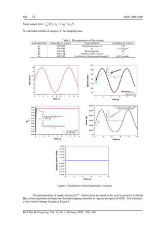
5. RESULTS AND SIMULATION
The simulation is realized in MATLAB/Simulink with the parameters of a 2.4MW machine.
In order to verify asymptotic stability of our controller and show its performance, we implemented
the system that includes wind turbine, (DFIG) and converter. The simulation has been realized for a wind
speed from 6 m/s to 12 m/s as shown in Figure 4. Table 1 shows the parameters of the DFIG based wind
turbine. In this paper, PSO is used to select efficient parameters of controller in order to converge rapidly to
the optimal functioning. PSO algorithm introduced by Kennedy and Eberhart in 1995 [24], is inspired by
social behavior of bird flocking or fish schooling, characterized as a simple structure. PSO algorithms use
particles which represent potential solutions of the problem. It is first initialized with a group of random
particles. In each iteration, every solution is modified at a certain velocity by following two best solutions
(fitness). The personal best 𝑃𝑏𝑒𝑠𝑡 which is the best value achieved by each solution and the global best 𝑔 𝑏𝑒𝑠𝑡
is the best value of all particles.
The position 𝑋𝑖 and the velocity 𝑌𝑖 of each particle of the population are defined as the following
two equations:
𝑌𝑖+1=ω.𝑌𝑖+𝑐1. 𝑟1(𝑃𝑏𝑒𝑠𝑡-𝑋𝑖)+ 𝑐2. 𝑟2(𝑔 𝑏𝑒𝑠𝑡 − 𝑋𝑖) (41) 𝑋𝑖+1=𝑌𝑖+1+𝑋𝑖 (42)
Where 𝑌𝑖 is the velocity of the particle, 𝑋𝑖 is the solution. 𝑟1 and 𝑟2 are random numbers. 𝑐1 and 𝑐2
are usually between 1.5 and 2.5 and finally ω is the inertia factor.
The PSO algorithm used in this paper consists of the following steps:
1. Population of particles is generated with random position and velocities (parameters 𝑘1, 𝑘2, 𝑘3 of
backstepping controller) (population size 50).
2. The fitness of each candidate solution is generated (40 and 25)
3. Select the 𝑃𝑏𝑒𝑠𝑡 and 𝑔 𝑏𝑒𝑠𝑡.Firt iteration:
4. Velocity updating : the velocities of all particles are edited according to equation of 𝑌𝑖+1
5. Position updating: the position of all particles are updated according to the (42)
6. Evaluate the fitness of each new individual
7. Compare the new individual with 𝑃𝑏𝑒𝑠𝑡 and 𝑔 𝑏𝑒𝑠𝑡.
8. Go back to step 4 until final iteration (maximum of iterations is 15)
9. Finally, the optimal position will be the solution of optimization problem.
In order to converge rapidly to the best solution, we minimize a certain criterion such as the mean
square error can be calculated by the following equation:](https://image.slidesharecdn.com/v3127sep5sep23feb18399amir-201203063233/85/PSO-Backstepping-controller-of-a-grid-connected-DFIG-based-wind-turbine-8-320.jpg)
![Int J Elec & Comp Eng ISSN: 2088-8708
PSO-Backstepping controller of a grid connected DFIG based wind turbine (Salmi Hassan)
865
Figure 5. Schematic of control strategy
To verify the robustness of this proposed controller, PSO-Backstepping is compared with arbitrary
backstepping controller which is implemented on recent works [26-29]. Figure 4 shows the simulation results
without parameters variations and the zoom of these resultants, respectively. Based on the results, it can be
seen that the rotor speed Ω, active power P and reactive power Q converge to their references with a
precision rate.in addition, the power coefficient is optimal (Cp = 0,44), which indicates that the power
extracted from the system is maximal. However, the backstepping controller with optimal parameters (𝐾1, 𝐾2
and 𝐾3) based on PSO algorithm permits to converge more quickly to the optimal trajectory than
the backstepping with parameters selected arbitrary. In order to evaluate the robustness of our controller with
presence of uncertainty, we have considered Δ𝐿 𝑟=Δ𝐿 𝑠 = Δ𝑀=5%, Δ𝑅 𝑟=90%, Δ𝐶 𝑃=6% and Δ𝜆=5%. It can be
seen in Figure 6 that the robustness of our proposed controller does not affected by the variation of DFIG’s
parameters and the speed Ω, active power P and reactive power Q converge to their optimal values.
In addition, the particle swarm optimization selects the best value of parameters for tracking rapidly the best
trajectory.
Figure 6. Simulation with parameters variation](https://image.slidesharecdn.com/v3127sep5sep23feb18399amir-201203063233/85/PSO-Backstepping-controller-of-a-grid-connected-DFIG-based-wind-turbine-10-320.jpg)
![ ISSN: 2088-8708
Int J Elec & Comp Eng, Vol. 10, No. 1, February 2020 : 856 - 867
866
6. CONCLUSION
From the outcome of our investigation, it is possible to conclude that the backstepping controller
with particle swarm optimization can solve the challenge of controlling the power extracted in presence of
DFIG’s parameters uncertainties, which is due to technical problem in the generator. The ABC algorithm is
applied to select the reference of rotational speed of wind turbine whatever the wind in order to extract
the maximum power in real time. The robustness of the controller is demonstrated by simulation results.
ACKNOWLEDGEMENTS
This work returns the framework of the research project SISA1 “Mini intelligent Power plant” between
research center SISA and our University. We are anxious to think the Hassan II University of Casablanca for
the financing of this project.
REFERENCES
[1] Li SH, Haskew TA, Williams KA, Swatloski RP, "Control of DFIG wind turbine with direct-current vector control
configuration," IEEE Trans Sustain Energy, vol. 3(1), pp. 1-11, 2012.
[2] D. Kumar et K. Chatterjee, "A review of conventional and advanced MPPT algorithms for wind energy systems,"
Renewable and Sustainable Energy Reviews, vol. 55, pp. 957-970, Mar. 2016.
[3] Lab-Volt Ltd., "Principles of doubly fed induction generators (DFIG)," Renewable energy, 2011.
[4] Hoang thinh do, Tri Dung Dang, Hoai Vu Anh Truong, Kyoung Kwan Ahn, "Maximum power point tracking and
output power control on pressure coupling wind conversion system," IEEE Transactions on Industrial Electronics,
vol. 65(2), Feb. 2018.
[5] C. Eddahmani, "A Comparative Study of Fuzzy Logic Controllers for Wind Turbine Based on PMSG,"
International Journal of Renewable Energy Research (IJRER), vol. 8(3), pp. 1386‑1392, sep. 2018.
[6] S. Kahla, Y. Soufi, M. Sedraoui, and M. Bechouat, "Maximum Power Point Tracking of Wind Energy Conversion
System Using Multi-objective grey wolf optimization of Fuzzy-Sliding Mode Controller," Int. J. Renew. Energy
Res. IJRER, vol. 7(2). pp. 926-936, Jun. 2017.
[7] M. Emna and K. Adel, "An Adaptive Backstepping Flux Observer for two Nonlinear Control Strategies Applied to
WGS based on PMSG," Int. J. Renew. Energy Res. IJRER, vol. 6(3), pp. 914-929, Sep. 2016.
[8] B. Beltran, M. E. H. Benbouzid and T. Ahmed-Ali, "Second-Order Sliding Mode Control of a Doubly Fed
Induction Generator Driven Wind Turbine," in IEEE Transactions on Energy Conversion, vol. 27(2), pp. 261-269,
Jun. 2012.
[9] S. Li, T. A. Haskew, K. A. Williams and R. P. Swatloski, "Control of DFIG Wind Turbine With Direct-Current
Vector Control Configuration," in IEEE Transactions on Sustainable Energy, vol. 3(1), pp. 1-11, Jan. 2012.
[10] Mullane, A., Lightbody, G., Yacamini, R., "Adaptive control of variable speed wind turbines," Rev. Energ. Ren.
Power Eng, pp. 101-110, 2001.
[11] A. Bektache, B. Boukhezzar, "Nonlinear predictive control of a DFIG-based wind turbine for power capture
optimization," International journal of electrical power & Energy systems, vol. 101, pp. 92-102, 2018.
[12] N. Bouchiba, A. Barkia, S. Sallem, L. Chrifi-Alaoui, S. Drid and M. Kammoun, "A real-time Backstepping control
strategy for a doubly fed induction generator based wind energy conversion system," 2017 6th International
Conference on Systems and Control (ICSC), Batna, 2017, pp. 549-554.
[13] Elmansouri, A., Elmhamdi, J., Boualouch, A., "Control by back stepping of the DFIG used in the wind turbine,"
Int. J.Emerg. Technol. Advanced Eng, vol. 5, pp. 472-478, 2015.
[14] Aounallah Tarek, Essounbouli Najib, Hamzaoui Abdelaziz, Bouchafaa Farid, "Algorithm on fuzzy adaptive
backstepping control of fractional order for doubly-fed induction generators," IET Renewable Power Generation,
vol. 12(8), pp. 962-967, 2018.
[15] Mohamed Nadour, Ahmed Essadki, Tamou Nasser, "Comparative analysis between PI & Backstepping control
strategies of DFIG driven by wind turbine," International journal of Renewable Energy Research, vol. 7(3), 2017.
[16] Bossoufi, B., Karim, M., Lagrioui, A., Taoussi, M., Derouich, A., "Adaptive backstepping control of DFIG
generators for variable-speed wind turbines system," J. Elect. Syst, vol. 10, pp. 317-330, 2014.
[17] Hassan Salmi, Abdelmajid Badri, Mourad Zegrari, Aicha Sahel and Abdennaceur Baghdad, "Artificial Bee Colony
MPPT control of Wind Generator without speed Sensors", International Conference on Electrical and Information
Technologies, ICEIT, 2017.
[18] Mechter A., Kemih K. and Ghanes M., "Backstepping control of a wind turbine for low wind speeds," Nonlinear
Dynamics, vol. 84, pp. 2435-2445, 2016.
[19] Belmokhtar, K., Doumbia, M.L., Agbossou, K., "Modeling and control of a dual-power asynchronous machine-
based wind turbine system for supplying power to the power grid (in French)," International Conference on
Electrical Engeneering (CIGE), pp. 54–62, 2010.
[20] Hoang thinh do, Tri Dung Dang, Hoai Vu Anh Truong, Kyoung Kwan Ahn, "Maximum power point tracking and
output power control on pressure coupling wind conversion system," IEEE Transactions on Industrial Electronics,
vol. 65(2), 2018.
[21] Meng Wu, Le Xie, "Calculation steady-state operating conditions for DFIG-based wind turbine," IEEE
Transactions on sustainable Energy, vol. 9(1), 2018.](https://image.slidesharecdn.com/v3127sep5sep23feb18399amir-201203063233/85/PSO-Backstepping-controller-of-a-grid-connected-DFIG-based-wind-turbine-11-320.jpg)
![Int J Elec & Comp Eng ISSN: 2088-8708
PSO-Backstepping controller of a grid connected DFIG based wind turbine (Salmi Hassan)
867
[22] Mohamed Nadour, Ahmed Essadki, Tamou Nasser, "Comparative analysis between PI & Backstepping control
strategies of DFIG driven by wind turbine," International journal of Renewable Energy Research, vol. 7(3), 2017.
[23] Mullane, A., Lightbody, G., "Yacamini, R.: Adaptive control of variable speed wind turbines," Rev. Energ. Ren.
Power Eng, pp. 101–110, 2001.
[24] T.K Roy, M.A Mahmud; S.N. Islam, M. T. Oo Amanullah, "Direct Power Controller Design for Improving FRT
Capabilities of DFIG-Based Wind Farms using a Nonlinear Backstepping Approach," 2018 8th International
Conference on Power and Energy Systems (ICPES), 2018.
[25] T.K Roy, M.A Mahmud, A.M.T. Oo, "Nonlinear Backstepping Controller Design for Improving Fault Ride
Through Capabilities of DFIG-Based Wind Farms," 2018 IEEE Power & Energy Society General Meeting
(PESGM), 2018.
[26] M El Ghamrasni, H Mahmoudi and B Bossoufi, "Modelling and simulation of a wind system using variable wind
regimes withBackstepping control of DFIG," 2018 IOP Conf. Ser.: Earth Environ. Sci. 161 012026, 2018.
[27] Adekanle O.S., Guisser M., Abdelmounim E., Aboulfatah M., "Observer-Based Adaptive Backstepping Control of
Grid-Connected Wind Turbine Under Deep Grid Voltage Dip," In: El Hani S., Essaaidi M. (eds) Recent Advances
in Electrical and Information Technologies for Sustainable Development. Advances in Science, Technology &
Innovation (IEREK Interdisciplinary Series for Sustainable Development), Springer, Cham, 2019.](https://image.slidesharecdn.com/v3127sep5sep23feb18399amir-201203063233/85/PSO-Backstepping-controller-of-a-grid-connected-DFIG-based-wind-turbine-12-320.jpg)