Download to read offline
![International Research Journal of Engineering and Technology (IRJET) e-ISSN: 2395-0056
Volume: 05 Issue: 12 | Dec 2018 www.irjet.net p-ISSN: 2395-0072
© 2018, IRJET | Impact Factor value: 7.211 | ISO 9001:2008 Certified Journal | Page 876
Decoupled control technique of DFIG with dual PWM converters for
Wind Power system using MATLAB/Simulink
Ananda DK1, Jaya Kumar N2
1PG Scholar, Dept. of Electrical Engineering, The Oxford College of Engineering, Karnataka, India.
2Associate Professor, Dept. of Electrical Engineering, The Oxford College of Engineering, Karnataka, India.
----------------------------------------------------------------------***---------------------------------------------------------------------
Abstract - Consequence of global environmental
variations, swelling fuel prices and increasing energy
demand in developing nations has directed the power
industry to adopt green energy generation concept using
renewable energy sources. Wind energy is one such
favorable option, with most widely adopted configuration
using Doubly Fed Induction Generator (DFIG) for variable
speed wind turbines. Stator windings of the DFIG are
directly connected to grid and rotor windings are fed by two
back to back connected power converters. This paper details
about decoupled control method for regulating the DFIG
based variable speed wind turbine. To plug the maximum
power from the wind Maximum Power Point Tracking
(MPPT) using indirect method is developed and Pulse Width
Modulation (PWM) technique is adopted for power
electronic converter. Proposed system is designed, developed
and simulated using MATLAB/SIMULINK
Key Words: Doubly Fed Induction Generator (DFIG),
Variable speed wind turbine, Wind Energy Systems
(WES), Maximum Power Point Tracking (MPPT),
Vector control, Back-to-Back Converters, Pulse Width
Modulation (PWM), MATLAB/SIMULINK.
1. INTRODUCTION
With increasing population, surge in the fossil fuel prices
and increasing apprehension about the release of
greenhouse gases, safety concerns regarding the usage of
nuclear fuels resulted in energy generation through
renewable energy sources. Day by day importance of
energy generation from renewable energy sources is
gaining more prominence. One such renewable source of
energy is Wind energy. Oil crisis during 1970’s encourage
to generate large amount of power through wind turbines.
Present-day wind power production cost and various
incentive schemes and initiative from government
agencies push the wind power generation to compete with
other conventional sources [1]. One of the most widely
used architecture in wind energy conversion system
(WECS) is based on Doubly Fed Induction Generator
(DFIG). There are various types of wind energy conversion
systems such as Horizontal axis wind turbines and vertical
axis wind turbines, but later one is more desirable. Stator
windings of DFIG are directly connected with grid and
rotor windings are connected to grid via back to back
connected PWM power converters. Main advantage with
this topology is power converter will handle 30% of the
generator power resulting in low rating of power
semiconductor components.
Control of DFIG is of prime importance since the wind
velocity may differ based on the geographical conditions
and the generator needs to respond to quick changes in
the wind speed with in short span of time [1] [2]. Many
control schemes have been suggested, among them vector
control strategy based on decoupling of rotor current
components either with stator flux oriented or stator
voltage oriented method will be adopted. The suggested
approach decouples the doubly fed induction generator
rotor current into two components to regulate active and
reactive power independently by implementing two
Proportional-Integral controllers. In order to extract
maximum power from the existing wind speed maximum
power point tracking [MPPT) with indirect speed control
approach is adopted. In order to increase the obtainable
output voltage Pulse width Modulation [PWM] with third
harmonic injection method is implemented. Complete
proposed system is illustrated in the Fig-1. The whole
system is developed and simulated using MATLAB/
SIMULINK.
Fig-1: Proposed system block diagram
From Fig-1 it is evident that DFIG is coupled with variable
speed wind turbine, the stator connects directly with grid
and rotor windings are fed by two back to back voltage
source converters namely rotor side converter [RSC] and
grid side converter [GSC]. A DC bus connects the two
voltage source converters. RSC regulates the active and
reactive power whereas GSC maintains the DC bus voltage
at constant magnitude.
2. WIND TURBINE MODELING
Kinetic energy of the wind results in rotary movement of
wind turbine blades converting moving energy of the wind](https://image.slidesharecdn.com/irjet-v5i12168-190103101555/75/IRJET-Decoupled-Control-Technique-of-DFIG-with-Dual-PWM-Converters-for-Wind-Power-System-using-MATLAB-Simulink-1-2048.jpg)
![International Research Journal of Engineering and Technology (IRJET) e-ISSN: 2395-0056
Volume: 05 Issue: 12 | Dec 2018 www.irjet.net p-ISSN: 2395-0072
© 2018, IRJET | Impact Factor value: 7.211 | ISO 9001:2008 Certified Journal | Page 877
into mechanical energy, which in turn gets converted into
electrical energy using generator. When wind blows past
the turbine blades bringing lift and apply rotational force.
The turbine blades revolve a shaft which in turn connects
with the gear box [2]. The gear box helps in increasing the
rotational speed from low speed shaft.
Power confined in the wind having wind speed (VW)
passing through the surface area of turbine blades (A) can
be given by
PW =0.5 AVW
3 …..(1)
Where = Density of the air in kg/m3
Certain portion of the power available in the wind can be
plugged by wind turbine. The mechanical power captured
by the wind turbine is found using
Pm= 0.5 R2VW
3Cp …..(2)
Where R= length of the turbine blades in mts, Cp is factor of
coefficient.
The Tip speed ratio is defined as the ratio of blade tip
speed to incoming wind speed [3]
…..(3)
Where Ωt = Wind turbine speed in rad/sec
Aerodynamic model signifies the power extraction of the
rotor, deriving mechanical torque as a function of air flow
on the turbine blades. Mechanical power captured by
turbine is expressed in terms of torque as below
Fig-2: Curve showing relationship between Ct and lamda
3. DOUBLY FED INDUCTION GENERATOR
Stator windings of DFIG machine is directly connected with
grid and rotor windings are connected to grid through back
to back arranged voltage source converters RSC and GSC.
Voltage source converter allows wide range of variable
speed operation of the wound rotor induction machine.
The capacitor which interlinks RSC and GSC acts as a
constant DC voltage source and like an energy storage
element. Converter control system generates switching
pulses to regulate rotor side converter and grid side
converter. RSC regulates the active power generated from
the wind turbine and GSC controls the Dc bus voltage and
reactive power. With the help of rotor side converter
voltage fed into the rotor windings of the DFIG can be
varied in order to control the rotor current.
At synchronous speed the magnetic field of the rotor
rotates at the same speed as that of the stator magnetic
field then the machine behaves like a asynchronous
machine with DC current in the rotor windings meaning
that no active power is generated from rotor windings and
all the active power from the machine will flow from stator
windings of the machine into the grid. When the wind
speed increases, rotor speed increases beyond the
synchronous speed causing negative slip resulting in super
synchronous operation with this condition both stator
windings and rotor windings of doubly fed induction
generator supplying power to the grid. When the wind
speed decreases the rotor speed of the DFIG reduces
causing positive slip and machine operates at sub
synchronous mode with this rotor windings absorbs power
from the grid consuming power for excitation of the rotor
windings[4].
3.1 DFIG Model
With the application of transformation matrix such as
Clarke and its inverse transformation three phase variable
quantities can be converted into two stationary quantities
referred to as quantities. With the help of rms value of
the components it is possible to find out the voltage
angle which is helpful in transforming the variables from
to dq frame by adopting parks transformation or vice
versa
…..(5)
Where = angle component
Equation 5 can be implemented in Matlab as
=atan2 [/]
In order to develop dynamic model of the DFIG space
vector theory is adapted to the basic equations of the
machine.
Fig-3: Various reference frames showing space vectors of
DFIM
Fig. 3 shows three different rotating reference frames used
to develop space vector based models of DFIG. Stator
reference frame is a stationary frame. Rotor reference
frame DQ rotates at m and synchronous reference frame
dq rotates at s . By using Clark, park and its inverse
transformations a space vector can be represented in any
of these frames [5].](https://image.slidesharecdn.com/irjet-v5i12168-190103101555/75/IRJET-Decoupled-Control-Technique-of-DFIG-with-Dual-PWM-Converters-for-Wind-Power-System-using-MATLAB-Simulink-2-2048.jpg)
![International Research Journal of Engineering and Technology (IRJET) e-ISSN: 2395-0056
Volume: 05 Issue: 12 | Dec 2018 www.irjet.net p-ISSN: 2395-0072
© 2018, IRJET | Impact Factor value: 7.211 | ISO 9001:2008 Certified Journal | Page 878
3.2 Model
Voltage equations of stator and rotor can be expressed in
terms of space vector representation
Expressing the stator voltage expression in stationary
reference frame as below
..... (8)
….. (9)
are the stator voltages, currents and flux linkages in
stationary reference frame. Rs, is stator windings resistance
in ohms..
Electromagnetic torque developed by the doubly fed
induction generator is given by
…..(10)
Where p= number of pole pairs
3.3 dq Model
Fig-4: DFIG Stator flux orientation in dq frame
Space vector model of the DFIG can also be represented in
synchronously rotating frame by multiplying the voltage
expression by e-js and e-jr for stator and rotor voltage
respectively. Hence dq voltage equations [5] can be
expressed as shown in the equations 13 and 14.
…..(11)
…..(12)
Expressing above voltage equations in dq coordinates
…..(13)
…..(14)
are the stator voltages,
currents and flux linkages in synchronous reference frame.
Rs, is the stator winding resistance in ohms.
Similarly electromagnetic torque developed by the DFIG in
dq coordinates is given by
…..(15)
4. CONTROL METHOD
DFIG based wind turbine systems consists of two
controllers referred as Rotor side converter and Grid side
converter. RSC regulates the active power and reactive
power where as GSC controls the DC-link voltage and
exchange of power between the grid [6].
4.1 Rotor Side Converter
Stator flux method of vector control technique is employed
such that direct axis aligned with stator flux component as
illustrated in the fig4. We know that stator flux is
proportional to grid voltage Vg.
Fig-5: Control approach of RSC
By neglecting the minute drop in the stator resistance gives
Vds=0; Vqs=Vg where s=ds and qs=0
Fig 5 represents the control block diagram of the rotor side
converter. To achieve the control measured three phase
voltage quantities are converted using Clarke’s
transformation to obtain alpha-beta components to obtain
stator flux, further the required angle is calculated for
parks transformation matrix to convert stator currents into
dq coordinates. This transformation helps us in finding out
the d and q- axis rotor current. Actual speed of the doubly
fed induction generator is measured and compared with
the reference speed, difference in the speed results in the
error signal which is being fed into the controller as the
input signal, controller output is torque reference which
provides the q-axis rotor current component. This
reference component is compared with the actual q-axis
rotor current and difference signal is provided as input
signal for the current controller to regulate the q-axis rotor
voltage component. Similarly one more PI current
controller will be employed to control the reactive power
[7]. By using inverse transformation equations two voltage
components are transferred back to three phase quantities
which results in generation of reference voltage signals for
PWM controller which in turn regulates the switching
pulses.](https://image.slidesharecdn.com/irjet-v5i12168-190103101555/75/IRJET-Decoupled-Control-Technique-of-DFIG-with-Dual-PWM-Converters-for-Wind-Power-System-using-MATLAB-Simulink-3-2048.jpg)
![International Research Journal of Engineering and Technology (IRJET) e-ISSN: 2395-0056
Volume: 05 Issue: 12 | Dec 2018 www.irjet.net p-ISSN: 2395-0072
© 2018, IRJET | Impact Factor value: 7.211 | ISO 9001:2008 Certified Journal | Page 879
4.2 Grid Side Converter
Objective of the grid side converter is to regulate the DC
link voltage and maintain unity power factor [8].
Mathematical of the inverter in alpha-beta model can be
represented as below
…..(16)
…..(17)
By multiplying the above equations by e-j
we can express
the equations in dq model [8] [9].
Fig-6: Block diagram of Grid side converter
Unity power factor is obtained by setting the reactive
power reference to zero. The DC reference voltage is
compared with the measured DC voltage across the DC bus
capacitor. The DC voltage regulator controls the Dc bus and
sets the active power which is essential to charge the
capacitor to the desired value [10]. The evolution of DC
voltage Vdc is given by the following equation
…..(18)
Where ic= capacitor current
5. SYSTEM MODELLING
Fig-7: Projected system representation using Simulink
Fig-7 shows the implementation of the proposed system
using Simulink. The entire system is made up of many
complex subsystems such as wind turbine aerodynamics,
maximum power tracking, Rotor side converter, Grid side
converter, these subsystems are implemented
autonomously and integrated to achieve the control of the
Doubly Fed Induction Generator. Some of the subsystems
are illustrated in the coming sections.
5.1 Wind Turbine
Fig-8: Representation of Wind turbine using Simulink
By considering the wind speed and turbine shaft speed it is
possible to find out the lambda value. By implementing
look up table torque coefficient is calculated. Subsequently
the ratio of the gear box must be considered to find out the
actual developed torque since the implemented system is
stated to lesser rotational shaft [11].
5.2 Maximum Power Tracking
Fig-9: Maximum power point tracking block
Objective of speed control strategy is to make best use of
the power extraction referring to the curve illustrating
power coefficient and lambda [12]. In order to realize
maximum power point tracking the control strategy
adopted is based on the technique mentioned as indirect
speed regulator method.
5.3 Rotor side control block
Fig-10: Rotor side control block implementation using
simulink
Control strategy implemented using Simulink for rotor side
converter is shown in the fig-10. Stator current and voltage
are transferred to suitable coordinate system to regulate
the system and corresponding Simulink blocks are shown.](https://image.slidesharecdn.com/irjet-v5i12168-190103101555/75/IRJET-Decoupled-Control-Technique-of-DFIG-with-Dual-PWM-Converters-for-Wind-Power-System-using-MATLAB-Simulink-4-2048.jpg)
![International Research Journal of Engineering and Technology (IRJET) e-ISSN: 2395-0056
Volume: 05 Issue: 12 | Dec 2018 www.irjet.net p-ISSN: 2395-0072
© 2018, IRJET | Impact Factor value: 7.211 | ISO 9001:2008 Certified Journal | Page 880
Fig-11: Implementation of angle block using Simulink
To transform the variables to various coordinate system
such as from three phase quantities into stationary alpha-
beta reference frame to rotating reference frame
transformation matrix are required. One such
transformation required angle theta [13] [14] for
transforming the components to dq coordinates. Fig-11
assists in finding the angle theta for such transformations.
Fig-12: Injection of third harmonic technique using
Simulink
In order to boost the peak value of the primary component
the block shown in the fig-12 is implemented such that it
injects third harmonics into the voltage reference signal
[15] to achieve maximum achievable output voltage.
5.4 Grid side control block
Fig-13: Grid side control block implementation using
Simulink
6. SIMULATION RESULTS
6.1 Considering Wind speed of 8 meters per second
Fig-14: Simulation curve illustrating revolving speed of
DFIG
Above graph represents the revolving speed of the DFIG
versus time. It is clearly visible that gradually speed is
increasing till 1 sec after the start of simulation and finally
to arrive at steady state 3 secs is required and will attain a
speed 137.5 rad./sec.
Fig-15: Response of reference and measured q- axis rotor
current
As discussed q- axis component regulates the torque, fig-15
shows the response of real and measured q-axis
component of rotor current.
Fig-16: Response of reference and measured
electromagnetic torque
From the figure it is observed that initially there will be lot
of disturbances due to startup of the machine which is not
recommended method of startup. It can be observed that
around 0.9 secs after the startup the measured torque
follows the reference value.](https://image.slidesharecdn.com/irjet-v5i12168-190103101555/75/IRJET-Decoupled-Control-Technique-of-DFIG-with-Dual-PWM-Converters-for-Wind-Power-System-using-MATLAB-Simulink-5-2048.jpg)
![International Research Journal of Engineering and Technology (IRJET) e-ISSN: 2395-0056
Volume: 05 Issue: 12 | Dec 2018 www.irjet.net p-ISSN: 2395-0072
© 2018, IRJET | Impact Factor value: 7.211 | ISO 9001:2008 Certified Journal | Page 882
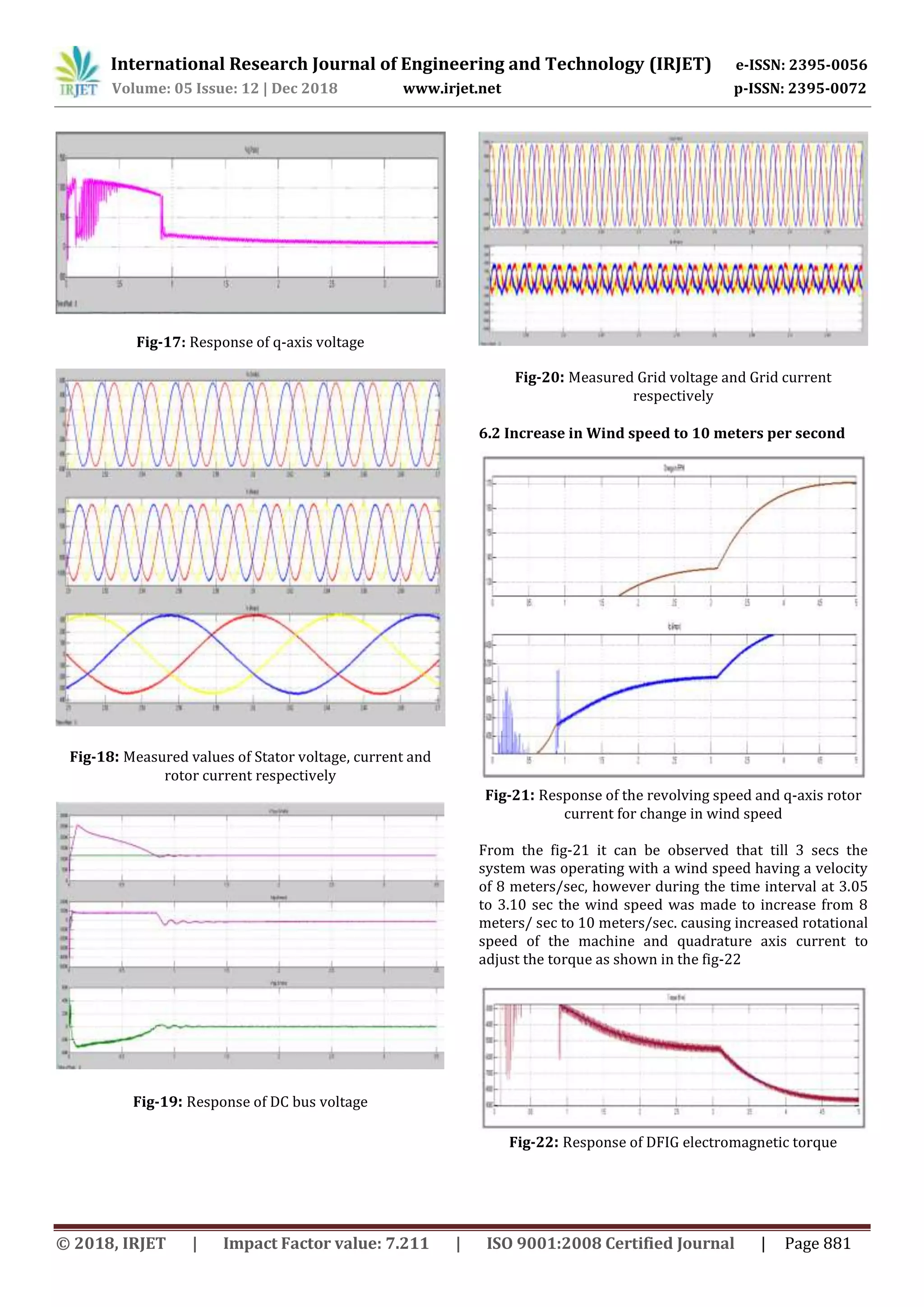
Fig-23: Quadrature axis voltage Response for change in
wind speed
Fig-24: Response of stator voltage, current and rotor
currents respectively
From the fig 24 it is evident that for a variation in wind
speed it is clearly noticeable that there is a change in the
magnitudes of the stator current and rotor currents. It is
also observable that rotor current experiencing
disturbance at the time interval 3.5 secs for change in
wind speed.
Fig-25: Response of DC bus voltage for change in wind
speed
6.3 Generator Data
Table -1: Generator data
Description Values Description Values
Nominal
Power
2000KW Frequency 50HZ
Nominal
speed
1500RPM
Number of
pole pairs
2
Nominal
Voltage
stator
0.69KV
Stator
resistance
2.6mΩ
Nominal
voltage
rotor
2070V
Rotor
Resistance
2.6mΩ
CONCLUSION
This paper presents the control approach implemented in
regulating the Doubly Fed Induction Generator for wind
energy systems. Detailed modeling of wind turbine
aerodynamics, grid side converter and rotor side
converter are presented. Maximum power point tracking
based on indirect speed control approach is adopted to
plug the maximum energy from the wind. As illustrated in
the previous sections decouple control strategy aids in
achieving the control of grid side and rotor side converter
to regulate the machine speed, electromagnetic torque,
active and reactive power and DC bus voltage. The system
is designed, modelled and simulated using the
MATLAB/Simulink software. Hence Doubly Fed Induction
Generator is appropriate solution for such systems as it
can easily adapts itself for different wind velocity.
REFERENCES
[1] Yu Zou, Malik E Elbuluk, Yilmaz Sozer, “simulation
comparison and implementation of induction generator
wind power sytems,” IEEE Trans. Ind. Appl. vol.49, No.3,
May/June 2013.
[2] Milkias Berhanu Tuka, Roberto Ledihold, Mengesha
Mamo, Modeling and control of a doubly fed induction
generator using a back to back converters in grid tied
wind power system. Presented at IEEE PES-IAS power
Africa 2017.
[3] Sergio Busquets-Monge, Joan Rocabert, Pedro
Rodriguez, Salvador Alepuz, Josep Bordonau, “Multilevel
diode clamped converter for photovoltaic genertaors with
independent voltage control of each solar array”, IEEE
trans.on Ind. Elecs, 2008, Vol.55, pp 2713-2723.
[4]G Abad, J. Lopez, M.A. Rodriguez L. Marroyo and G.
Iwanski, “ Vector control strategies for grid connected
DFIM wind turbines”, in doubly fed induction machine:](https://image.slidesharecdn.com/irjet-v5i12168-190103101555/75/IRJET-Decoupled-Control-Technique-of-DFIG-with-Dual-PWM-Converters-for-Wind-Power-System-using-MATLAB-Simulink-7-2048.jpg)
![International Research Journal of Engineering and Technology (IRJET) e-ISSN: 2395-0056
Volume: 05 Issue: 12 | Dec 2018 www.irjet.net p-ISSN: 2395-0072
© 2018, IRJET | Impact Factor value: 7.211 | ISO 9001:2008 Certified Journal | Page 883
Modeling and control for wind energy generation, John
wiley & sons, Inc, 2011. P.304.
[5] Haitham Abu-Rub, Mariusz Malinowski and kamal Al-
Haddad, power electronics for renewable energy systems,
transportation and industrial applications, 2014, IEEE
press and John Wiley and sons ltd.
[6] Y Bekakra, D.B. Attous, “ Active and reactive power
control of a DFIG with MPPT for variable speed wind
energy conversion using sliding mode control”, World
academy of science, engineering and technology 60, 2011.
[7] Badrul H. Chowdhury and Srinivas Chellapilla,”Double-
fed induction generator control for variable speed wind
power generation”, Electric power systems research,
volume 76, Issues 9-10, June 2006, pp. 786-800
[8] Amirnaser Yazdani, Reza Iravani, “ Voltage sourced
converters in power systems, Modeling, control and
applications,” 2010, John wiley and sons inc.
[9] Singh B, Naidu N.K.S, “ Direct power control of single
VSC based DFIG without rotor position sens,” IEEE trans.
Ind.appl.2014,50,4152-4163.
[10] CM Rahul Charles, V Vinod, Anju Jacob – Field
oriented control of doubly fed induction generator in wind
power system. Presented at IEEE international conference
on computational intelligence and computing research
2015.
[11] Vijay Chand Ganti, Bhim Singh, Shiv Kumar Aggarwal,
“DFIG based wind power conversion with Grid power
Levelling for reduced gusts,” IEEE Trans. Sustainable
Energy. vol3, No.1 Jan 2012.
[12] G Venu Madhav and Y P Obulesu, “ Direct torque
control strategy for doubly fed induction machine under
low voltage dips”, IJPEDS, vol.2, No.4, December 2012, pp.
409-416 2012.
[13] E. Muljadi and CP Butterfield, “ Pitch-controlled
variable speed wind turbine generation”, IEEE
Transcations on industry applications, vol.37, No.1,
January/February 2001
[14] R Pena and J.C. Clare, “ Doubly fed induction
generator using back to back pwm converters and its
application to variable speed wind energy generation”,
proc. IEEE, Electric power applications, vol.143, No.3,
pp.231-241, May 1996.
[15] Remus Teodorescu, Macro Liserre and Pedro
Rodriguez, Grid converters for photovoltaic and wind
power systems, First edi.2011, John Wiley and sons, Ltd.](https://image.slidesharecdn.com/irjet-v5i12168-190103101555/75/IRJET-Decoupled-Control-Technique-of-DFIG-with-Dual-PWM-Converters-for-Wind-Power-System-using-MATLAB-Simulink-8-2048.jpg)

This document presents a decoupled control technique for regulating a Doubly Fed Induction Generator (DFIG) used in variable speed wind turbine systems. The DFIG has its stator windings directly connected to the grid, while its rotor windings are connected to the grid via back-to-back PWM converters. The proposed system uses vector control and MPPT to independently control active and reactive power output. It develops decoupled control of the DFIG rotor currents and uses PI controllers to regulate the converters. The complete system is modeled and simulated in MATLAB/Simulink to validate the control approach.