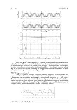
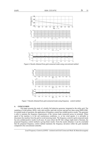
This paper discusses the load frequency control of doubly fed induction generators (DFIG) in both isolated and grid-connected modes, highlighting the advantages of wind energy as a renewable source. The proposed method showed improved performance in frequency regulation compared to conventional control systems, with successful modeling and simulation conducted using MATLAB/Simulink. Key findings demonstrate that frequency control maintains grid standards and is crucial for reliable system operation.

![ISSN: 2252-8792
IJAPE Vol. 1, No. 1, April 2012 : 29 – 36
30
power fluctuations and improved VAr supply. These large wind turbines are based on either variable wind
speed with pitch control using a synchronous generator or a doubly fed induction generator.
Doubly-fed induction generators have two active windings the stator and rotor; both the windings
transfer significant power to the electrical system. The major advantage of using doubly fed machine is that
the power consumed by the power electronic equipment is (20-30%) of total power supply [1]. The stator
winding is connected directly to the grid and the rotor windings are controlled by using power electronic
converters.
Juan Dixon in [2] explained about different types of three phase controlled rectifiers and their
control using PWM signals. The control method for DC link voltage was also explained. In [3],
Balasubramaniam, Babypriya and Rajapalan Anita simulated the DFIG using MATLAB and analyzed
various DFIG characteristics. In [5], B.Chitti Babu and K.B.Mohanty presented the complete modeling and
simulation of wind turbine driven Doubly Fed Induction Generator that feeds AC power to the utility grid.
The AC-DC-AC converters are divided into two components, the rotor side rectifier and the grid side
inverter. Both are voltage source converters. The capacitor connected on the dc side acts as the dc voltage
source. Rotor side converter is used to control the output power and the voltage measured at the grid
terminals. The grid side converter is used to regulate the voltage of the dc bus capacitor by Branislav,
Dosijanoski in [6-8]. In [9-10], Mariusz Malinowski presented the mathematical model and operation
description of PWM rectifier. Different control strategies for PWM rectifiers were also described.
2. RESEARCH METHOD
The DFIG technology extracts maximum energy from low wind speeds and minimizes mechanical
stresses on the turbine. Another advantage of the DFIG technology is the ability for power electronic
converters to generate or absorb reactive power, thus eliminating the need for installing capacitor banks as in
the case of squirrel-cage induction generator [5].
2.1 Operating principle of DFIG
The stator connected to the ac mains, where as the rotor feeds power via back to back PWM
converters. The DC bus capacitor link connects stator and rotor-side converters. To achieve full control of
grid current, the DC-link voltage must be boosted to a level higher than the amplitude of grid line-to-line
voltage [2]. The slip power flows from rotor to the grid. The speed of the machine can be controlled from
either rotor or stator-side converter for all speed ranges. As a result, the machine can be controlled as a
generator in both super and sub-synchronous operating modes realizing four quadrant operations. In this
project only generation mode is considered. At the synchronous speed, slip power is taken from supply to
excite the rotor windings and in this case machine behaves as a synchronous motor. The power delivered by
the rotor and the stator are computed as follows [7]:
(1)
(2)
For a loss less generator the mechanical equation is
(3)
In steady-state at fixed speed for a loss less generator
(4)
(5)
) = ( =
(6)
Where,
(7)](https://image.slidesharecdn.com/1280-932-1-pb-201203032521/85/Load-Frequency-Control-of-DFIG-isolated-and-Grid-Connected-Mode-2-320.jpg)
![IJAPE ISSN: 2252-8792
Load Frequency Control of DFIG - Isolated and Grid Connected Mode (K.Manickavasagam)
31
Generally the absolute value of slip is much lower than 1 and, consequently, Pr is only a fraction of Ps [8]
- If s>0, Tm is negative, ωr is positive thus power is delivered to the grid
- For super synchronous speeds, Pr is transmitted to DC bus capacitor and tends to increase the DC voltage
Inverter is used to generate the power Pgc in order to keep the DC voltage constant. In steady-state, for a
lossless AC/DC/AC converter Pgc is equal to Pr. The frequency of rotor induced voltage is equal to the
product of the grid frequency and the absolute value of the slip as in Eqn. 2.6. Rectifier and Inverter have the
capability for generating or absorbing reactive power and could be used to control the reactive power or the
voltage at the grid terminals [1].
2. 2. Load Frequency Control
The usual practice of generating PWM pulses is by comparing the DC voltage obtained from rotor
side rectifier with a reference voltage. These PWM pulses are used to trigger the switches of inverter. The
block diagram of such a controller scheme is shown in Figure . .3.In this work, the grid frequency is
considered as a feedback to the frequency control method. The frequency regulator block consists of PLL,
comparator and PI controller. PLL is used to convert three phase grid voltage into a proportional frequency
and this frequency is given to the comparator. The comparator compares the load side and reference
frequencies. PI controller performs a control action based on the error produced by the comparator. This
output is the Idgc_ref that is same as that in the conventional control system. The currents Id and Iq are fed to
a current regulator that generates the required Vgc. PWM generator uses this control voltage Vgc to generate
pulses for the control of the grid side inverter. Grid frequency control is essential to ensure stable and reliable
operation of the system. The block diagram of frequency control is as shown in Figure 2. Figure 3 indicates
the block diagram of grid frequency based control of grid side inverter.
Figure 2. Conventional controllers for grid side
inverter
Figure 3. Grid frequency based control of grid side
inverter
2.3. Modeling of wind turbine
Wind turbine is intended towards conversion of the kinetic energy inherent in the wind due to its
motion into useful mechanical energy that can be used to generate electrical energy. The inherent power of
the wind in the form of kinetic energy can be expressed by the following equation:
(8)
Now the power extracted by the mechanical turbine is only a portion of the available kinetic energy of the
wind. The performance of power coefficient Cp in a turbine is expressed as the ratio of power developed by
the turbine to the power of the wind which is expressed as follows [10]
(9)
Alternatively,
(10)
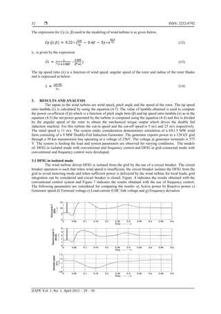
Thus the net mechanical power developed by the turbine is given by the equation
(11)](https://image.slidesharecdn.com/1280-932-1-pb-201203032521/85/Load-Frequency-Control-of-DFIG-isolated-and-Grid-Connected-Mode-3-320.jpg)
![ISSN: 2252-8792
IJAPE Vol. 1, No. 1, April 2012 : 29 – 36
36
REFERENCES
[1] Ahmed G. Abo-Khalil, Dong-Choon Lee and Se-Hyun Lee, “ Grid Connection of Doubly-Fed Induction Generators
in Wind Energy Conversion System,” IEEE 2006, IPEMC 2006
[2] Juan Dixon (Ph.D.), “Three Phase Controlled Rectifier” www.ebookfree-download.com/.../three-phase-controlled-
rectifiers-p...Cached
[3] Balasubramaniam Babypriya, Rajapalan Anita, “Modelling, Simulation and Analysis of Doubly-Fed Induction
Generation for Wind Turbines” Journal of Electrical Engineering, Vol. 60, NO. 2, 2009, 79–85
[4] Remus Teodorescu and Frede Blaabjerg, “Flexible control of small wind turbines with grid failure detection
operating in stand-alone and grid-connected mode” IEEE transactions on power elctronics, Vol 19,no.5,September
2004
[5] B. Chitti Babu, K.B Mohanty,“Doubly-Fed Induction Generator for Variable Wind Energy Conversion Systems-
Modeling and Simulation,” International Journal of Computer and Electrical Engineering, Vol. 2, No. 1, February,
2010 1793-8163
[6] Branislav Dosijanoski, “Simulation of Doubly-Fed Induction generator in a Wind Turbine”, XI International PhD
Workshop OWD 2009,17-20 October 2009
[7] Richard Gagnon, Gilbert Sybille, Serge Bernard, Daniel Paré, Silvano Casoria, Christian Larose, “Modeling and
Real-Time Simulation of a Doubly-Fed Induction Generator Driven by a Wind Turbine,” IPST’05, June 19-23,
2005, Paper No. IPST05-162
[8] I. Margaris A. Tsouchnikas and N. Hatziargyriou, “ Simulation of Doubly-Fed Induction Generator Wind
Turbines” Website: www.docstoc.com
[9] Mariusz Malinowski, “Sensor less Control Strategies for Three - Phase PWM Rectifiers” Ph.D. Thesis,Warsaw,
Poland – 2001
[10] Tomas petru,“Modelling of wind Turbines for Power System Studies”, PhD Thesis, Goteborg, Sweden 2003.
Website: http://webfiles.portal.chalmers.se/et/PhD/PetruTomasPhD.pdf
BIBLIOGRAPHY OF AUTHORS
K.Manickavasagam received the PhD from Madurai Kamaraj University, M.E.Degree from
Thiagarajar College of engineering, Madurai, Tamilnadu, India. Currently he is working in
Gopalan College of Engineering and Management, Bangalore, Karnataka, India. His reseach
interests includes Power generation and control and artificial intelligence applications in power
systems. He is a member of the Institute of engineers (India) and life member of Indian
Society of Technical Education.](https://image.slidesharecdn.com/1280-932-1-pb-201203032521/85/Load-Frequency-Control-of-DFIG-isolated-and-Grid-Connected-Mode-8-320.jpg)