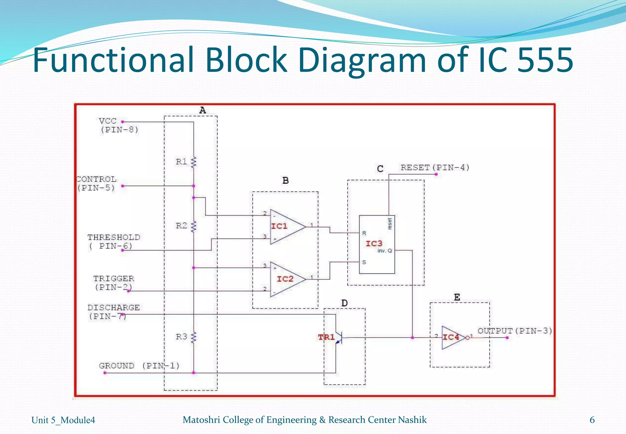
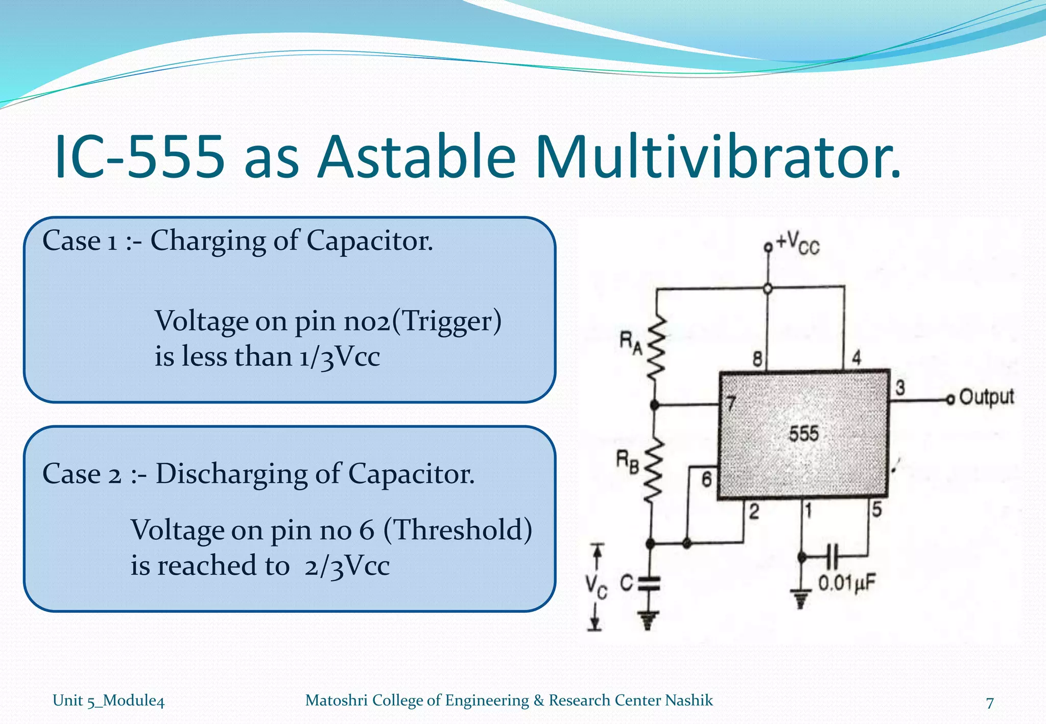
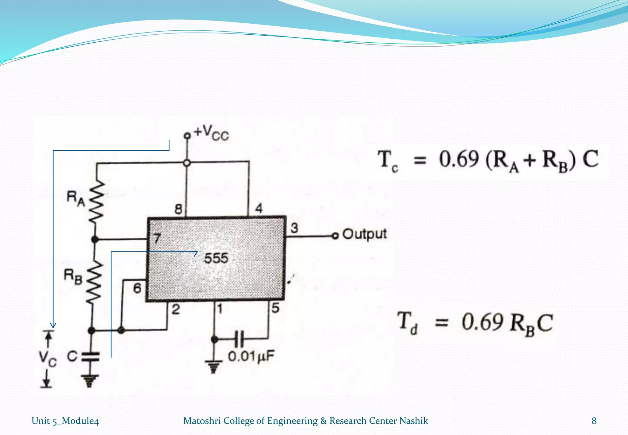
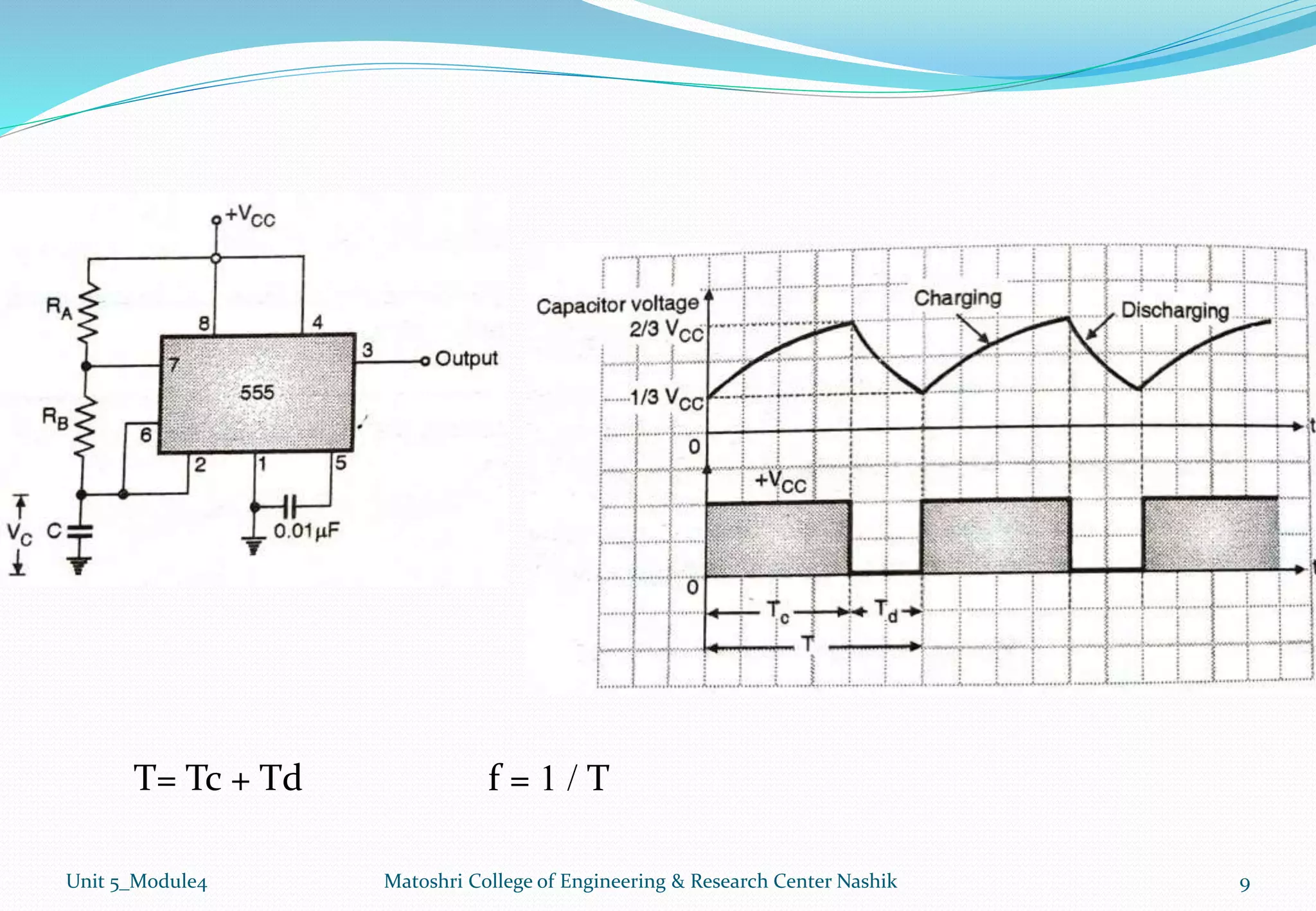
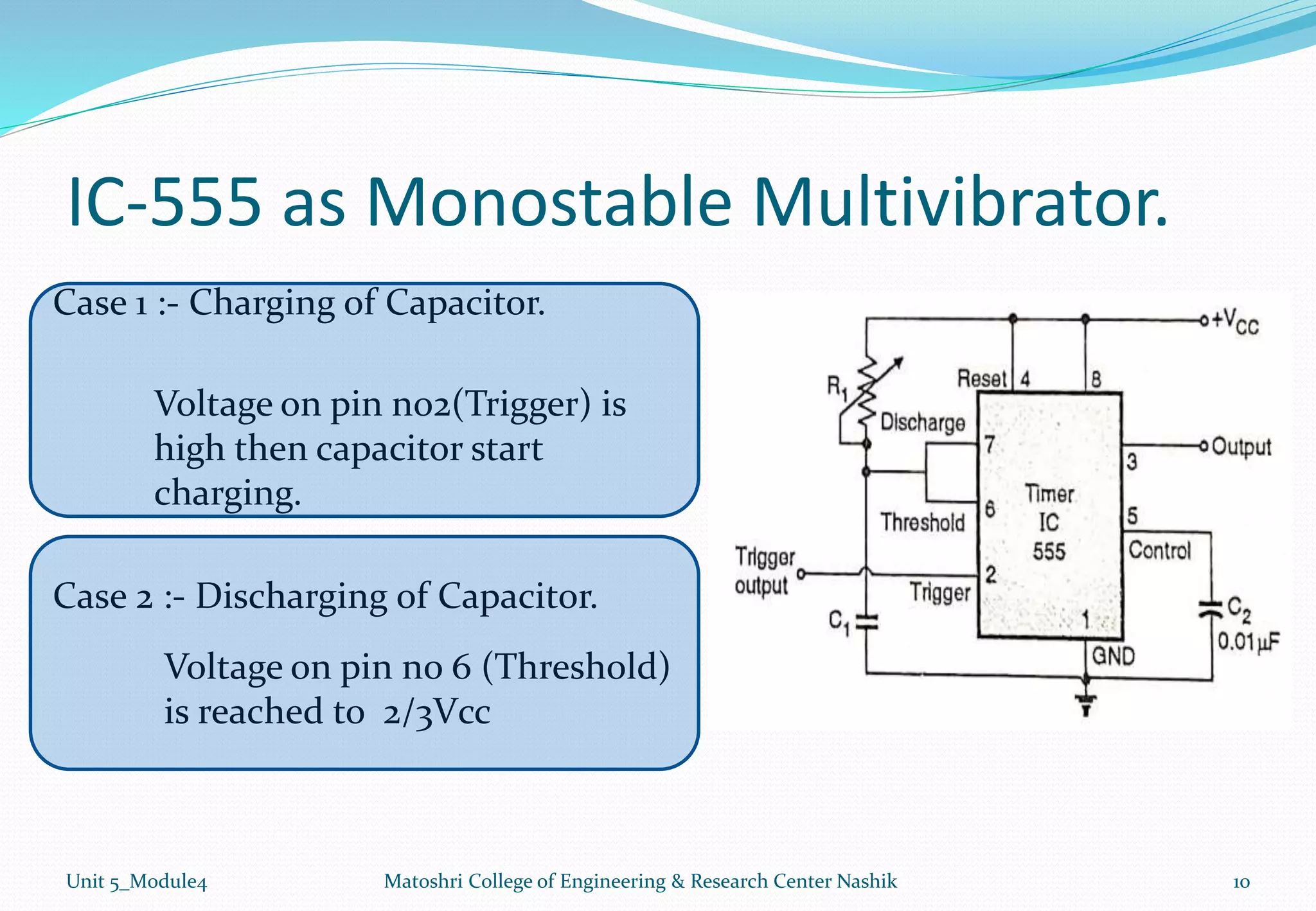
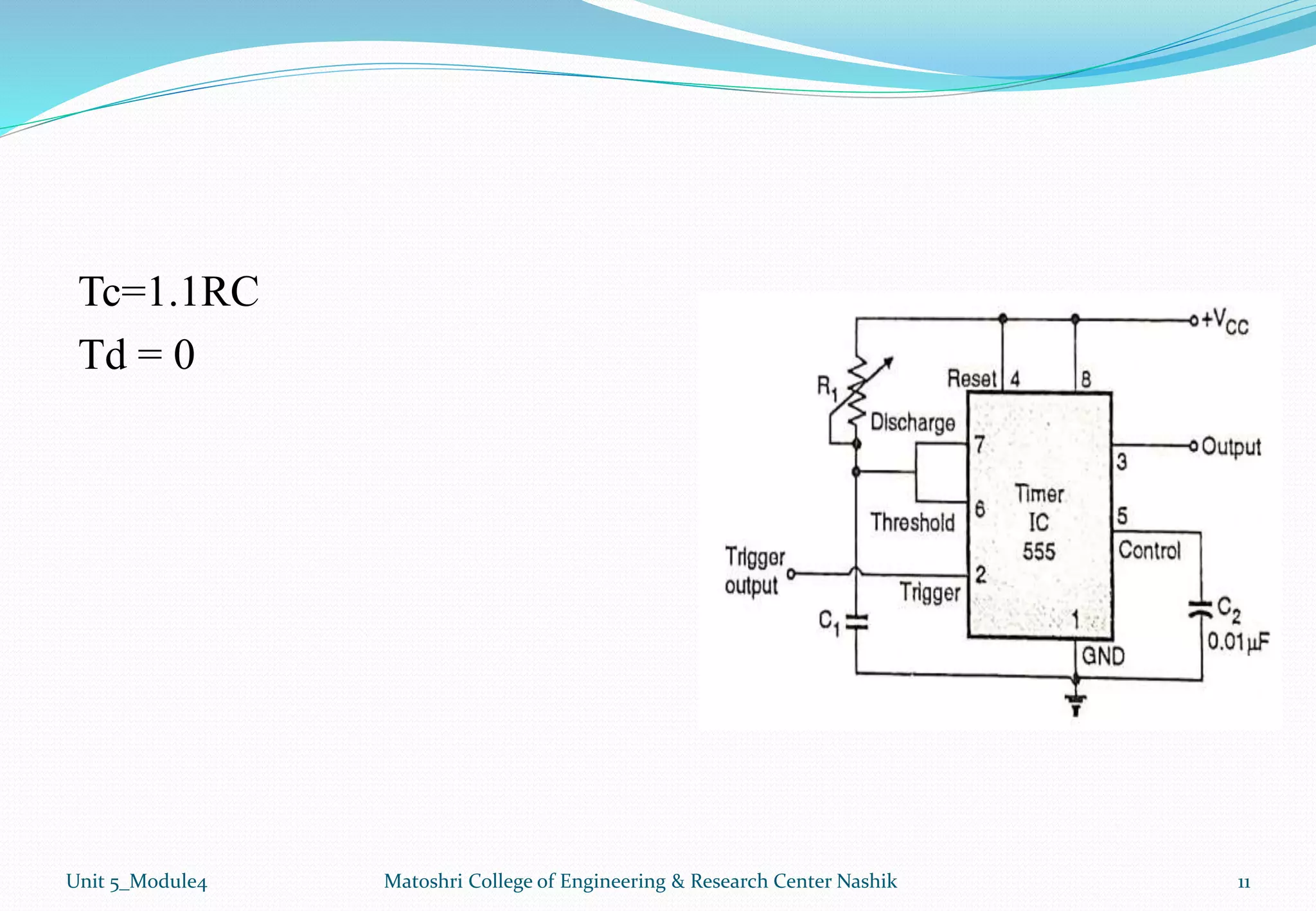
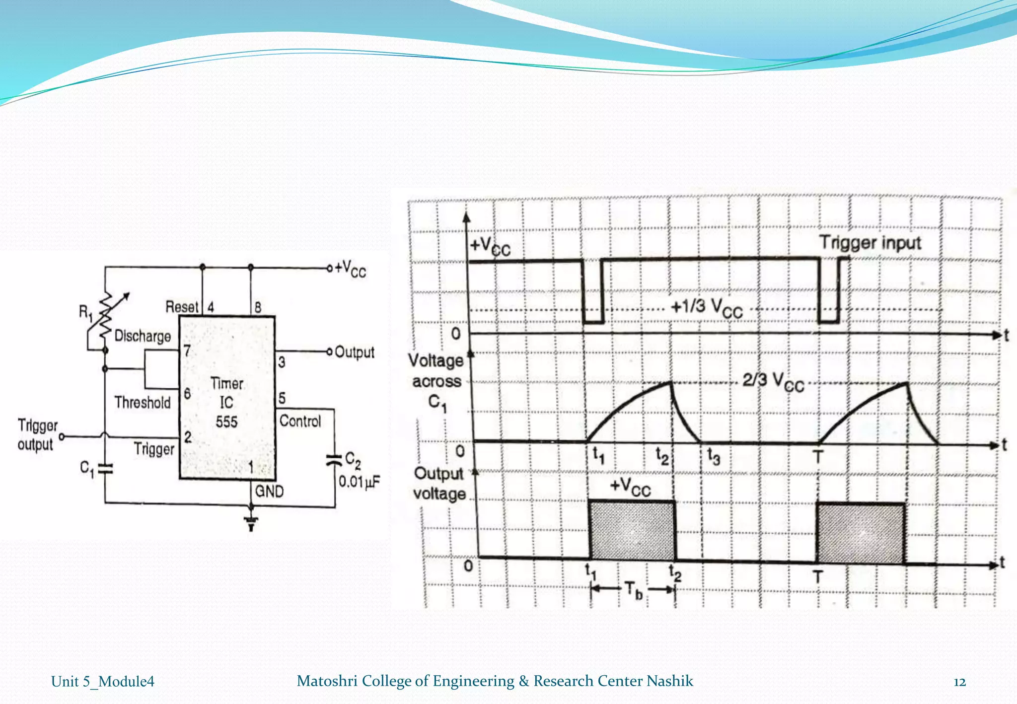
By
Mr. C.R.Shinde
Electrical Engineering Department
Matoshri College of Engineering & Research centre, Nashik
Unit 05: Other Analog circuits:-
1. Active filters-Its configuration with frequency response
2. Analysis of first order low pass and high pass filters using OPAMP.
3. IC 555 –construction, working .
4. IC 555 –astable and monostable multi vibrators, Sequence generator
5. voltage regulators using IC78xx, 79xx, LM 317
2
Matoshri College of Engineering & Research Center Nashik
Unit 5_Module4
IC 555 –astable and monostable multi
vibrators, Sequence generator
3
Matoshri College of Engineering & Research Center Nashik
Unit 5_Module4
Content.
1. Introduction to Multivibrator.
2. IC-555 as Astable Multivibrator.
3. IC-555 as Monostable Multivibrator.
4. IC-555 as Sequence Generator.
Unit 5_Module4 Matoshri College of Engineering & Research Center Nashik 4
Introduction to Multivibrator.
 Multivibrator is an electronics circuit which can have no,
one or two stable state of operation.
 Depending on the number of stable state we can classify
the multivibrator as shown below.
Unit 5_Module4 Matoshri College of Engineering & Research Center Nashik 5
Multivibrator
Astable Monostable Bistable
Functional Block Diagram of IC 555
Unit 5_Module4 Matoshri College of Engineering & Research Center Nashik 6
IC-555 as Astable Multivibrator.
Unit 5_Module4 Matoshri College of Engineering & Research Center Nashik 7
Case 1 :- Charging of Capacitor.
Case 2 :- Discharging of Capacitor.
Voltage on pin no2(Trigger)
is less than 1/3Vcc
Voltage on pin no 6 (Threshold)
is reached to 2/3Vcc
Unit 5_Module4 Matoshri College of Engineering & Research Center Nashik 8
Unit 5_Module4 Matoshri College of Engineering & Research Center Nashik 9
T= Tc + Td f = 1 / T
IC-555 as Monostable Multivibrator.
Unit 5_Module4 Matoshri College of Engineering & Research Center Nashik 10
Case 1 :- Charging of Capacitor.
Case 2 :- Discharging of Capacitor.
Voltage on pin no2(Trigger) is
high then capacitor start
charging.
Voltage on pin no 6 (Threshold)
is reached to 2/3Vcc
Tc=1.1RC
Td = 0
Unit 5_Module4 Matoshri College of Engineering & Research Center Nashik 11
Unit 5_Module4 Matoshri College of Engineering & Research Center Nashik 12
Thank you
Mr. C. R. Shinde
Electrical Engineering Department
Matoshri College of Engineering & Research centre, Nashik
If you have any query, ask me anytime on…… … .. . . .
cshinde58@gmail.com
chandrakant.shinde@matoshri.edu.in
9970031353
13
Matoshri College of Engineering & Research Center Nashik
Unit 5_Module4

Module 4 :Ic 555 As A Astable & Monostable Multivibrator

  • 1.
    By Mr. C.R.Shinde Electrical EngineeringDepartment Matoshri College of Engineering & Research centre, Nashik
  • 2.
    Unit 05: OtherAnalog circuits:- 1. Active filters-Its configuration with frequency response 2. Analysis of first order low pass and high pass filters using OPAMP. 3. IC 555 –construction, working . 4. IC 555 –astable and monostable multi vibrators, Sequence generator 5. voltage regulators using IC78xx, 79xx, LM 317 2 Matoshri College of Engineering & Research Center Nashik Unit 5_Module4
  • 3.
    IC 555 –astableand monostable multi vibrators, Sequence generator 3 Matoshri College of Engineering & Research Center Nashik Unit 5_Module4
  • 4.
    Content. 1. Introduction toMultivibrator. 2. IC-555 as Astable Multivibrator. 3. IC-555 as Monostable Multivibrator. 4. IC-555 as Sequence Generator. Unit 5_Module4 Matoshri College of Engineering & Research Center Nashik 4
  • 5.
    Introduction to Multivibrator. Multivibrator is an electronics circuit which can have no, one or two stable state of operation.  Depending on the number of stable state we can classify the multivibrator as shown below. Unit 5_Module4 Matoshri College of Engineering & Research Center Nashik 5 Multivibrator Astable Monostable Bistable
  • 6.
    Functional Block Diagramof IC 555 Unit 5_Module4 Matoshri College of Engineering & Research Center Nashik 6
  • 7.
    IC-555 as AstableMultivibrator. Unit 5_Module4 Matoshri College of Engineering & Research Center Nashik 7 Case 1 :- Charging of Capacitor. Case 2 :- Discharging of Capacitor. Voltage on pin no2(Trigger) is less than 1/3Vcc Voltage on pin no 6 (Threshold) is reached to 2/3Vcc
  • 8.
    Unit 5_Module4 MatoshriCollege of Engineering & Research Center Nashik 8
  • 9.
    Unit 5_Module4 MatoshriCollege of Engineering & Research Center Nashik 9 T= Tc + Td f = 1 / T
  • 10.
    IC-555 as MonostableMultivibrator. Unit 5_Module4 Matoshri College of Engineering & Research Center Nashik 10 Case 1 :- Charging of Capacitor. Case 2 :- Discharging of Capacitor. Voltage on pin no2(Trigger) is high then capacitor start charging. Voltage on pin no 6 (Threshold) is reached to 2/3Vcc
  • 11.
    Tc=1.1RC Td = 0 Unit5_Module4 Matoshri College of Engineering & Research Center Nashik 11
  • 12.
    Unit 5_Module4 MatoshriCollege of Engineering & Research Center Nashik 12
  • 13.
    Thank you Mr. C.R. Shinde Electrical Engineering Department Matoshri College of Engineering & Research centre, Nashik If you have any query, ask me anytime on…… … .. . . . cshinde58@gmail.com chandrakant.shinde@matoshri.edu.in 9970031353 13 Matoshri College of Engineering & Research Center Nashik Unit 5_Module4