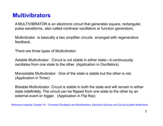
Multivibrators are electronic circuits that generate square and pulse waveforms, classified into three types: astable, monostable, and bistable. Astable multivibrators oscillate continuously, monostable multivibrators have one stable state, and bistable multivibrators can remain in either stable state until triggered. Key concepts include duty cycle, circuit stability, and the configurations of timing components that determine oscillation frequency.
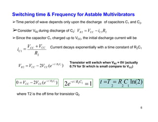
![Switching time & Frequency for Astable Multivibrators
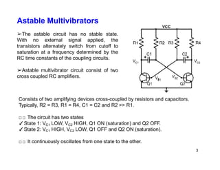
➢Similarly off time for transistor Q1 can be obtained.
➢Total time period T:
T T T [R C R C ]ln(2) 0.694(R C R C )
1 2 3 2 2 1 3 2 2 1
t T1 R3C2 ln(2)
7
➢If R2 = R3 = R, C1 = C2 = C then T 1.4RC
➢Frequency of oscillation is given by
f
1
0.7
T RC](https://image.slidesharecdn.com/multivibrators-240422063543-8344e1b7/85/Multivibrators-Astable-Bistable-and-Monostable-pptx-6-320.jpg)