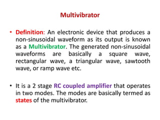
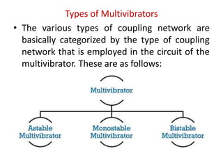
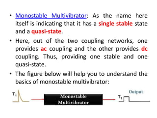
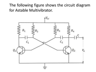
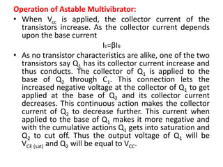
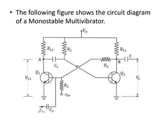
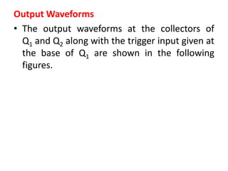
The document discusses different types of multivibrators including astable, monostable, and bistable multivibrators. It provides details on the construction, operation, and output waveforms of each type. Astable multivibrators have no stable states and continuously oscillate between two states. Monostable multivibrators have one stable state and require a trigger pulse to change states. Bistable multivibrators have two stable states and require a trigger pulse to change between the states. Applications of each type are also discussed.
The document discusses insulated gate bipolar transistors (IGBTs). It describes IGBTs as having MOSFET-like input characteristics and bipolar junction transistor-like output characteristics. The document summarizes IGBT structure, working principles, characteristics including transfer and switching characteristics, and methods of connecting IGBTs in series and parallel. It also discusses protection of IGBTs from overvoltage, overcurrent, high dv/dt, and overheating.
The document discusses different types of multivibrators, including bistable, monostable, and astable multivibrators. A multivibrator is an electronic circuit that generates non-sinusoidal oscillations using switching elements like transistors. Bistable multivibrators have two stable states, monostable multivibrators have one stable state and need a trigger, and astable multivibrators have no permanent stable states and oscillate continuously between two quasi-stable states. Common applications include using bistable multivibrators as memory elements, monostable multivibrators as timing circuits, and astable multivibrators as square wave generators.
An operational amplifier (op-amp) is an integrated circuit that can amplify or compare signals. It consists of transistors, resistors, and capacitors. Op-amps are used to build amplifiers, summers, integrators, differentiators, and comparators. They obey golden rules to make the difference between their input pins zero. Op-amps are also used in analog to digital converters, which sample analog signals and convert them to digital signals for processing.
A tuned amplifier uses a tuned circuit in the load to selectively amplify signals of a desired frequency. It employs the phenomenon of resonance to pass a narrow band of frequencies centered around the resonant frequency of the tuned circuit. Tuned amplifiers are commonly used in radio transmitters and receivers to select and amplify the carrier frequency from a mixture of frequencies. They can be classified as small signal or large signal amplifiers depending on the power level and class of operation. Common circuit configurations include single tuned, double tuned, and stagger tuned amplifiers.
The document is a presentation on silicon controlled rectifiers (SCRs) given by five students. It introduces SCRs, explaining that they are power electronic devices that can convert AC to DC and control power to a load. The presentation describes the basic structure and operation of SCRs, including how applying a voltage to the gate terminal allows current to flow. It also covers the characteristics curve and applications of SCRs in areas like rectification, power supplies, motor controls and battery charging. In conclusion, SCRs are widely used power components due to their ability to easily switch high currents and their low cost.
An amplifier is an electronic device that increases the voltage, current, or power of a signal. Feedback is defined as part of the output signal being returned to the input. Positive feedback occurs when the feedback signal is in phase with the original input signal, while negative feedback occurs when they are out of phase. Positive feedback is used in oscillators to generate an output frequency and in amplifiers to produce smooth signals from noisy inputs, but it increases gain and the risk of oscillation while reducing frequency response and increasing distortion.
The document discusses the unijunction transistor (UJT) and programmable unijunction transistor (PUT). It describes their equivalent circuits, characteristics, and use in relaxation oscillator circuits. The UJT equivalent circuit includes two resistors (one fixed, one variable) and a diode. The PUT can be programmed by an external voltage divider to turn on at a certain voltage. Both devices can be used in relaxation oscillator circuits where the capacitor charges and discharges through the transistor and resistors to generate oscillating waveforms.
An insulated-gate bipolar transistor (IGBT) is a three-terminal semiconductor device that combines high efficiency and fast switching. It consists of alternating P-N-P-N layers controlled by a metal-oxide-semiconductor (MOS) gate structure, without regenerative action. The IGBT structure is similar to a thyristor with an isolated MOS gate that completely suppresses the thyristor action. IGBTs are used in switching power supplies for applications requiring high power, such as variable frequency drives, electric vehicles, and air conditioners. The IGBT combines the simple gate drive of MOSFETs with the high-current and low-saturation-voltage capabilities of bipolar transistors.
A multivibrator is a circuit that switches between two voltage levels. There are three types: bistable, which has two stable states; monostable (one-shot), which has one stable state and produces a single output pulse in response to a trigger; and astable (oscillator), which continuously switches between states with no trigger needed. Resistors and capacitors are often used to control the timing of monostable and astable multivibrators. The 555 timer IC can be configured as either a monostable or astable multivibrator.
1) Alternating current (AC) refers to sinusoidal voltage and current waveforms. AC can be generated from sources like AC generators, wind turbines, hydroelectric power plants, and solar panels.
2) Key characteristics of AC waveforms include instantaneous value, peak amplitude, peak value, peak-to-peak value, period, frequency, phase, and whether they are periodic.
3) Sinusoidal waves can be expressed as v = Vm sin(ωt+θ), where Vm is the peak amplitude, ω is the angular frequency, t is time, and θ is the phase. The phase relationship between two sinusoidal waves indicates whether one leads or lags the other.
Filters are electrical circuits that pass specified frequency bands while attenuating signals outside that band. They are classified as active or passive. Active filters have advantages like smaller size and weight due to integrated components, and they do not load signal sources. However, they have limitations like finite bandwidth and sensitivity to temperature changes. Common filters include low pass, high pass, band pass, band stop, and all pass filters. State variable filters can produce multiple filter responses and are called universal filters.
A chopper is a static device that uses pulse width modulation or variable frequency control to obtain a variable DC output voltage from a constant DC input voltage. Choppers are widely used to control motors and regenerate braking energy. The document describes different types of choppers - Type A chops the input voltage to produce positive output voltage and current. Type B allows regenerative braking by producing negative current. Type C operates in both quadrants while Type D's output voltage can be positive or negative.
Power point presentation on logical families.
A good presentation cover all topics.
For any other type of ppt's or pdf's to be created on demand contact -dhawalm8@gmail.com
mob. no-7023419969
The document summarizes key aspects of a half-wave rectifier circuit. It defines a half-wave rectifier as a circuit that converts only the positive or negative half of the AC input cycle to DC. It describes how a basic half-wave rectifier works using a single diode to allow only one half of the AC cycle to pass. It also provides equations for calculating the average, RMS, and maximum efficiency of the rectified output signal. Finally, it briefly discusses the ripple factor, form factor, and advantages of simplicity and low cost for a half-wave rectifier design.
The document discusses different types of time base generators used to generate output voltage or current waveforms that vary linearly with time. It describes voltage time base generators and current time base generators. It then discusses various circuits used to implement these generators, including exponential sweep circuits, constant current sweep circuits, UJT sweep circuits, and Miller and bootstrap time base generators. The Miller and bootstrap generators aim to produce a linear output by using feedback to keep the capacitor charging current constant. Transistor implementations of Miller and bootstrap generators are also covered.
Digital voltmeters display voltage measurements numerically rather than with an analog needle. There are several types of digital voltmeters including ramp, integrating, continuous-balance, and successive-approximation types. A ramp digital voltmeter works by converting the input voltage into a digital equivalent by counting the time taken for an internally-generated ramp wave to decrease from the input voltage magnitude to 0 volts. It does this using a voltage-to-time conversion section that compares the input to the ramp and a time measurement section with a counter to measure the time.
Comparator circuits compare two input voltages and produce a logic output signal that is high or low depending on which input is larger. Real comparators do not have an abrupt transition and have very high voltage gain in the transition region. Comparators are often used as interfaces between analog and digital circuits by converting analog signals to logic levels. Open-collector outputs are useful for this by producing either 0V or the supply voltage at their outputs. Schmitt triggers, which are comparators with positive feedback, are commonly used as they introduce hysteresis which helps eliminate unwanted output transitions from noise.
AC voltage controllers are thyristor-based devices that can vary the output voltage of an AC supply without changing frequency. They use phase control or integral cycle control strategies to control power flow. Applications include heating, lighting control, and motor speed control. A continuous gating signal is required for full-wave controllers with RL loads to ensure thyristors turn off properly.
The document discusses different types of oscillators. It begins by describing the basic concept and principles of operation for oscillators. RC and LC oscillators are analyzed in more detail. RC oscillators like the Wien bridge and phase-shift oscillators are described as generating signals in the kHz range using RC timing circuits. LC oscillators like the Colpitts, Hartley, and crystal oscillators can generate higher frequency signals from hundreds of kHz to hundreds of MHz using LC tuned circuits or crystals in the feedback network. The key conditions for oscillation are also summarized.
This document presents an overview of operational amplifiers (op-amps). It begins with an introduction to op-amps, followed by their circuit symbol, pin diagram, important terms and equations. It describes the ideal properties of an op-amp, as well as non-ideal behaviors. Applications discussed include analog to digital converters, current sources, and zero crossing detectors. Advantages are listed as versatility and uses in various circuits. Disadvantages include limitations in power and load resistance.
This article discusses different power electronics devices that are in use like power diodes, power thyristors, power transistors, IGBT, GTO, IGCT and others. This article will give a basic view of these devices and their operations.
FREQUENCY ENTRAINMENT IN A WIEN BRIDGE OSCILLATORSwgwmsaBoro
1. The document reports on a student project studying the frequency of a Wien bridge oscillator.
2. It introduces the Wien bridge oscillator and how it produces continuous oscillations using an RC feedback network and amplifier.
3. The students analyze the frequency of their Wien bridge oscillator circuit experimentally and find that frequencies above 1MHz cannot be achieved due to limitations of the op-amp used.
PowerPoint Presentation on using IC 555 Timer as an Astable Multi vibrator. Working of the astable multi vibrator, advantages and disadvantages of an Astable Multi-vibrator,Input and Output Pins of 555 IC, Formulae for calculating the charge and discharge time and cycle time of the astable multi vibrator.
Class A amplifiers have the highest linearity because the transistor is always conducting. They are the least efficient at 30% due to continuous power loss. Class B amplifiers only conduct for half of the signal cycle, improving efficiency to 50% but introducing crossover distortion. Class AB balances efficiency and distortion by conducting more than half but less than the full cycle. Class C amplifiers have the greatest efficiency of 80% but introduce heavy distortion as they conduct for less than half of the input cycle. They are used for radio frequency amplification rather than audio.
The document discusses the unijunction transistor (UJT), a three-terminal semiconductor device with one PN junction. It consists of a lightly doped silicon bar with a heavily doped P-type material alloyed to one side, forming the single junction. The UJT has three terminals - an emitter, and two bases B1 and B2. When a voltage is applied across B2-B1, the UJT exhibits a negative resistance characteristic, allowing it to be used as an oscillator. Once triggered by a pulse at one of its terminals, the emitter current increases regeneratively until a limiting value is reached. Applications of the UJT include phase control, switching, pulse generation, and timing circuits.
This document discusses different types of multivibrators including astable, monostable, and bistable multivibrators. It provides details on their construction, operation, waveforms, and applications. A multivibrator is a switching circuit that generates non-sinusoidal waves like square waves. It has two possible states and switches between these states for certain time periods. The main types are the astable multivibrator which continuously switches states on its own, the monostable which has one stable and one triggered state, and the bistable which has two stable states that require a trigger to switch.
This document discusses various types of multivibrators and transistor switching circuits. It begins by explaining how a transistor can be used as a switch by applying voltage to its base terminal. It then discusses different types of multivibrators (astable, monostable, bistable) and provides examples of each, including explaining their circuit operation. The document also covers MOSFETs and how they can function as switches. It concludes by briefly describing the 555 timer integrated circuit and some of its applications and features.
Electrical current, voltage, resistance, capacitance, and inductance are a few of the basic elements of electronics and radio. Apart from current, voltage, resistance, capacitance, and inductance, there are many other interesting elements to electronic technology. ... Use Electronics Notes to learn electronics online.
The document discusses different types of multivibrator circuits. It begins with introducing Shahid uz Jaman Shah and Samiul Isam, their names, rolls, and departments. It then provides definitions and circuit diagrams of astable, monostable, and bistable multivibrators. For each type, it explains the circuit operation and characteristics, provides applications, and discusses frequency of oscillation for astable multivibrators. Overall, the document presents information on three main types of multivibrator circuits: astable, monostable, and bistable.
Oscillators generate an output signal without an input signal by converting DC power to AC power. They produce periodic waveforms like sine, square, triangle, and sawtooth waves. The Wien bridge oscillator is a two-stage RC coupled amplifier circuit that is stable at its resonant frequency. It uses a feedback circuit of series and parallel RC networks to produce a phase shift. Monostable multivibrators have one stable and one quasi-stable state. They switch to the quasi-stable state when triggered externally and return to the stable state after a set time period determined by resistor-capacitor values in the circuit.
This document discusses three types of multivibrator circuits:
1. Astable multivibrators continually switch between two quasi-stable states without any external input. They are used as oscillators to produce a square wave output.
2. Monostable multivibrators have one stable state but can be triggered externally to another temporary state, producing a single output pulse before returning to the stable state.
3. Bistable multivibrators have two stable states and can be switched between them by external trigger pulses, functioning like a flip-flop.
A dual converter is an electronic device that combines two bridges, where one bridge acts as a rectifier to convert AC to DC and the other acts as an inverter to convert DC back to AC. There are two main types - single phase and three phase dual converters. In operation, one converter acts as a rectifier while the other acts as an inverter to provide reversible DC power. Dual converters are commonly used for speed control of DC motors in industrial applications where reversible DC power is required.
Unit 7 Multivibrator (Using Transistor) By Dr. Meenakshi Rana.pdfnath479500
This document discusses different types of multivibrators, including astable, monostable, and bistable multivibrators. It describes the circuitry and operation of each type. Astable multivibrators generate oscillating square waves without external triggers. Monostable multivibrators have one stable state and one temporary state, changing states upon receiving a trigger pulse. Bistable multivibrators have two stable states and change states only when triggered, then remaining in that state. Common applications include timers, oscillators, and storing digital information.
The document discusses various types of power electronics converters. It describes thyristors and their operation in forward blocking, forward conduction, and reverse blocking modes. It then explains different power electronics converter circuits - AC to DC converters (rectifiers), DC to AC converters (inverters), DC to DC converters (choppers), and AC to AC converters. AC to DC converters are further divided into half wave and full wave controlled rectifiers, with their circuit diagrams and working explained.
1) The document discusses different types of oscillators including phase shift oscillators, Colpitts oscillators, and Hartley oscillators.
2) Phase shift oscillators use RC networks to generate a 180 degree phase shift, while Colpitts oscillators use a tapped inductor and two capacitors in a tank circuit to produce feedback.
3) Key advantages of these oscillator circuits include good frequency stability, the ability to generate very low frequencies, and not requiring large inductors.
1) The document discusses different types of oscillators including phase shift, Colpitts, Hartley, and crystal oscillators.
2) Phase shift oscillators use RC networks to generate a 180 degree phase shift instead of inductive coupling. Colpitts oscillators use a tapped inductor and two capacitors in a tank circuit.
3) Hartley oscillators use inductive coupling between two coils to provide feedback. Crystal oscillators use a piezoelectric crystal that resonates at a precise frequency in a feedback loop to generate stable oscillations.
The document describes the Colpitts oscillator circuit. It consists of an LC tank circuit made of capacitors and an inductor that produces sustained oscillations. The capacitors provide positive feedback to sustain oscillations at the resonant frequency of the tank circuit. It works by the energy transferring between the capacitors and inductor in the tank circuit. The Colpitts oscillator can generate high frequency sinusoidal waves and is commonly used as a local oscillator in radio receivers [END SUMMARY]
Cycloconverters are used to convert AC power directly to AC power of variable magnitude and frequency. They have four main advantages over conventional AC to DC to AC conversion: they do not require an intermediate DC link, allow bidirectional power flow, can produce high quality sine waves at low frequencies without filters, and are line commutated without a separate commutation circuit. Cycloconverters are commonly used to drive large induction and synchronous motors at frequencies from 0-20Hz, such as in cement mill, ship propulsion, rolling mill, and mine applications. However, they have disadvantages of not allowing smooth stepless frequency control, producing more distortion at low frequencies, and having a more complex control circuit design.
This document discusses dual converters, which comprise two converters - one that performs rectification and the other performs inversion. It begins with an introduction and provides a block diagram. It then explains the principles of operation in both non-circulating and circulating current modes. Four quadrant operation is also discussed. Ideal dual converters have ripple-free output voltage. The document concludes by covering types of dual converters (single and three-phase) and their applications such as controlling DC motor direction and speed.
CHINA’S GEO-ECONOMIC OUTREACH IN CENTRAL ASIAN COUNTRIES AND FUTURE PROSPECTjpsjournal1
The rivalry between prominent international actors for dominance over Central Asia's hydrocarbon
reserves and the ancient silk trade route, along with China's diplomatic endeavours in the area, has been
referred to as the "New Great Game." This research centres on the power struggle, considering
geopolitical, geostrategic, and geoeconomic variables. Topics including trade, political hegemony, oil
politics, and conventional and nontraditional security are all explored and explained by the researcher.
Using Mackinder's Heartland, Spykman Rimland, and Hegemonic Stability theories, examines China's role
in Central Asia. This study adheres to the empirical epistemological method and has taken care of
objectivity. This study analyze primary and secondary research documents critically to elaborate role of
china’s geo economic outreach in central Asian countries and its future prospect. China is thriving in trade,
pipeline politics, and winning states, according to this study, thanks to important instruments like the
Shanghai Cooperation Organisation and the Belt and Road Economic Initiative. According to this study,
China is seeing significant success in commerce, pipeline politics, and gaining influence on other
governments. This success may be attributed to the effective utilisation of key tools such as the Shanghai
Cooperation Organisation and the Belt and Road Economic Initiative.
Embedded machine learning-based road conditions and driving behavior monitoringIJECEIAES
Car accident rates have increased in recent years, resulting in losses in human lives, properties, and other financial costs. An embedded machine learning-based system is developed to address this critical issue. The system can monitor road conditions, detect driving patterns, and identify aggressive driving behaviors. The system is based on neural networks trained on a comprehensive dataset of driving events, driving styles, and road conditions. The system effectively detects potential risks and helps mitigate the frequency and impact of accidents. The primary goal is to ensure the safety of drivers and vehicles. Collecting data involved gathering information on three key road events: normal street and normal drive, speed bumps, circular yellow speed bumps, and three aggressive driving actions: sudden start, sudden stop, and sudden entry. The gathered data is processed and analyzed using a machine learning system designed for limited power and memory devices. The developed system resulted in 91.9% accuracy, 93.6% precision, and 92% recall. The achieved inference time on an Arduino Nano 33 BLE Sense with a 32-bit CPU running at 64 MHz is 34 ms and requires 2.6 kB peak RAM and 139.9 kB program flash memory, making it suitable for resource-constrained embedded systems.
Redefining brain tumor segmentation: a cutting-edge convolutional neural netw...IJECEIAES
Medical image analysis has witnessed significant advancements with deep learning techniques. In the domain of brain tumor segmentation, the ability to
precisely delineate tumor boundaries from magnetic resonance imaging (MRI)
scans holds profound implications for diagnosis. This study presents an ensemble convolutional neural network (CNN) with transfer learning, integrating
the state-of-the-art Deeplabv3+ architecture with the ResNet18 backbone. The
model is rigorously trained and evaluated, exhibiting remarkable performance
metrics, including an impressive global accuracy of 99.286%, a high-class accuracy of 82.191%, a mean intersection over union (IoU) of 79.900%, a weighted
IoU of 98.620%, and a Boundary F1 (BF) score of 83.303%. Notably, a detailed comparative analysis with existing methods showcases the superiority of
our proposed model. These findings underscore the model’s competence in precise brain tumor localization, underscoring its potential to revolutionize medical
image analysis and enhance healthcare outcomes. This research paves the way
for future exploration and optimization of advanced CNN models in medical
imaging, emphasizing addressing false positives and resource efficiency.
Harnessing WebAssembly for Real-time Stateless Streaming PipelinesChristina Lin
Traditionally, dealing with real-time data pipelines has involved significant overhead, even for straightforward tasks like data transformation or masking. However, in this talk, we’ll venture into the dynamic realm of WebAssembly (WASM) and discover how it can revolutionize the creation of stateless streaming pipelines within a Kafka (Redpanda) broker. These pipelines are adept at managing low-latency, high-data-volume scenarios.
International Conference on NLP, Artificial Intelligence, Machine Learning an...gerogepatton
International Conference on NLP, Artificial Intelligence, Machine Learning and Applications (NLAIM 2024) offers a premier global platform for exchanging insights and findings in the theory, methodology, and applications of NLP, Artificial Intelligence, Machine Learning, and their applications. The conference seeks substantial contributions across all key domains of NLP, Artificial Intelligence, Machine Learning, and their practical applications, aiming to foster both theoretical advancements and real-world implementations. With a focus on facilitating collaboration between researchers and practitioners from academia and industry, the conference serves as a nexus for sharing the latest developments in the field.
Presentation of IEEE Slovenia CIS (Computational Intelligence Society) Chapte...University of Maribor
Slides from talk presenting:
Aleš Zamuda: Presentation of IEEE Slovenia CIS (Computational Intelligence Society) Chapter and Networking.
Presentation at IcETRAN 2024 session:
"Inter-Society Networking Panel GRSS/MTT-S/CIS
Panel Session: Promoting Connection and Cooperation"
IEEE Slovenia GRSS
IEEE Serbia and Montenegro MTT-S
IEEE Slovenia CIS
11TH INTERNATIONAL CONFERENCE ON ELECTRICAL, ELECTRONIC AND COMPUTING ENGINEERING
3-6 June 2024, Niš, Serbia
Optimizing Gradle Builds - Gradle DPE Tour Berlin 2024Sinan KOZAK
Sinan from the Delivery Hero mobile infrastructure engineering team shares a deep dive into performance acceleration with Gradle build cache optimizations. Sinan shares their journey into solving complex build-cache problems that affect Gradle builds. By understanding the challenges and solutions found in our journey, we aim to demonstrate the possibilities for faster builds. The case study reveals how overlapping outputs and cache misconfigurations led to significant increases in build times, especially as the project scaled up with numerous modules using Paparazzi tests. The journey from diagnosing to defeating cache issues offers invaluable lessons on maintaining cache integrity without sacrificing functionality.
KuberTENes Birthday Bash Guadalajara - K8sGPT first impressionsVictor Morales
K8sGPT is a tool that analyzes and diagnoses Kubernetes clusters. This presentation was used to share the requirements and dependencies to deploy K8sGPT in a local environment.
KuberTENes Birthday Bash Guadalajara - K8sGPT first impressions
Multivibrators.pptx
1. SANSKRITHI SCHOOL OF ENGINEERING
SANSKRITHI SCHOOL OF BUSINESS
Presentation
By
D.Nagarju
Director Public Relations, University
Relations and Accreditations
On
Multi Vibrators
3. Multivibrator
• Definition: An electronic device that produces a
non-sinusoidal waveform as its output is known
as a Multivibrator. The generated non-sinusoidal
waveforms are basically a square wave,
rectangular wave, a triangular wave, sawtooth
wave, or ramp wave etc.
• It is a 2 stage RC coupled amplifier that operates
in two modes. The modes are basically termed as
states of the multivibrator.
4. Basics of Multivibrator
• The multivibrator is a switching circuit and its
basic configuration is shown below:
5. • Here, two amplifiers are employed in which
the output from the 1st stage acts as input to
the 2nd stage. The output of the 2nd stage is
then through a feedback path is provided to
the input of the 1st stage.
• Here, the operation of the circuit is controlled
by two conditions on and off of the circuit. It
performs oscillations between high and low
state i.e., 0 and 1 thereby generating a
continuous output.
6. Types of Multivibrators
• The various types of coupling network are
basically categorized by the type of coupling
network that is employed in the circuit of the
multivibrator. These are as follows:
7. Astable multivibrator: It is a type of
multivibrator also termed as a free running
multivibrator. It is called so because here the
state changes on its own after some
predetermined time interval and thus does
not require a triggering pulse.
• Here, the output of the circuit simply
oscillates between high and low state freely.
Hence is just an oscillator.
8. The figure below shows the configuration of an
astable multivibrator:
A phase shift of 180° is provided by each amplifier
stage in the mid-band, thereby generating a total
phase shift of 0° or 360°. Hence providing positive
feedback.
9. • Thus, the circuit has no stable state, and the
two states are merely temporary ones termed
as quasi-state.
• So, a continuous output is generated by
performing successive transitions from one
state to another after a fixed time duration.
• It is to be noted here that the time duration of
switching between one quasi-state to the
other depends on the time constant and
other parameters of the circuit.
10. • Monostable Multivibrator: As the name here
itself is indicating that it has a single stable state
and a quasi-state.
• Here, out of the two coupling networks, one
provides ac coupling and the other provides dc
coupling. Thus, providing one stable and one
quasi-state.
• The figure below will help you to understand the
basics of monostable multivibrator:
11. • Unlike the astable multivibrator, here, a triggering
pulse is required in order to have transition from the
stable state to the quasi-state. However, in order to
have transition again from quasi-state to a stable
state no any triggering pulse is provided.
• So, to have a stable state again, a predetermined
timing interval is provided as given in case of the
astable multivibrator.
• Thus, after a certain time period decided by the time
constant, the circuit comes back to its initial state
i.e., the stable state without the need of external
signal.
12. Bistable multivibrator: A bistable multivibrator has
2 stable states. Here, a separate trigger pulse is
required in order to have transition from one
stable state to another stable state.
• Here, only dc coupling is provided by the coupling
networks and hence the energy storing element
is not required.
• Let us have a look at the pictorial configuration of
a bistable multivibrator
13. • When the trigger pulse is first applied, the
transistor in the circuit gets cut-off thus showing
an off stable state. However, as another triggering
pulse is applied, the transistor again starts its
conduction. Thereby changing its state from one
state to another.
• As the overall operation depends on two triggers,
these circuits are also termed as flip-flops or
trigger circuits. For the purpose of counting and
storing binary elements, bistable multivibrators
are used.
14. Applications of Multivibrators
• Astable Multivibrators finds its applications in delay and
timing circuits and in transmission and reception of radio
signals.
• Monostable multivibrators are majorly used in analog
systems in order to control the frequency of the signal at the
output. These are also used for regenerating a distorted
pulsed signal.
• Bistable multivibrators are also used as a frequency divider,
counters, latches and in memory storage units.
So, we can conclude that a multivibrator generates rectangular,
triangular, ramp or square waveform as its output. At the
same time, it has the ability to store binary information and
synchronizing multiple operations of a digital system.
15. Astable Multivibrator
• An astable multivibrator has no stable states. Once
the Multivibrator is ON, it just changes its states on
its own after a certain time period which is
determined by the RC time constants. A dc power
supply or Vcc is given to the circuit for its operation.
Construction of Astable Multivibrator:
Two transistors named Q1 and Q2 are connected in
feedback to one another. The collector of transistor
Q1 is connected to the base of transistor Q2 through
the capacitor C1 and vice versa. The emitters of both
the transistors are connected to the ground. The
collector load resistors R1 and R4 and the biasing
resistors R2 and R3 are of equal values. The capacitors
C1 and C2 are of equal values.
17. Operation of Astable Multivibrator:
• When Vcc is applied, the collector current of the
transistors increase. As the collector current depends
upon the base current
Ic=βIB
• As no transistor characteristics are alike, one of the two
transistors say Q1 has its collector current increase and
thus conducts. The collector of Q1 is applied to the
base of Q2 through C1. This connection lets the
increased negative voltage at the collector of Q1 to get
applied at the base of Q2 and its collector current
decreases. This continuous action makes the collector
current of Q2 to decrease further. This current when
applied to the base of Q1 makes it more negative and
with the cumulative actions Q1 gets into saturation and
Q2 to cut off. Thus the output voltage of Q1 will be
VCE (sat) and Q2 will be equal to VCC.
18. • The capacitor C1 charges through R1 and when
the voltage across C1 reaches 0.7v, this is enough
to turn the transistor Q2 to saturation. As this
voltage is applied to the base of Q2, it gets into
saturation, decreasing its collector current. This
reduction of voltage at point B is applied to the
base of transistor Q1 through C2 which makes the
Q1 reverse bias. A series of these actions turn the
transistor Q1 to cut off and transistor Q2 to
saturation. Now point A has the potential VCC.
The capacitor C2 charges through R2. The voltage
across this capacitor C2 when gets to 0.7v, turns
on the transistor Q1 to saturation.
19. • Hence the output voltage and the output
waveform are formed by the alternate
switching of the transistors Q1 and Q2. The
time period of these ON/OFF states depends
upon the values of biasing resistors and
capacitors used, i.e., on the RC values used. As
both the transistors are operated alternately,
the output is a square waveform, with the
peak amplitude of VCC.
20. Waveforms:
• The output waveforms at the collectors of Q1 and
Q2 are shown in the following figures.
21. Frequency of Oscillations
• The ON time of transistor Q1 or the OFF time of
transistor Q2 is given by
t1 = 0.69R1C1
• Similarly, the OFF time of transistor Q1 or ON time of
transistor Q2 is given by
t2 = 0.69R2C2
• Hence, total time period of square wave
t = t1 + t2 = 0.69(R1C1 + R2C2)
• As R1 = R2 = R and C1 = C2 = C, the frequency of
square wave will be
22. Advantages
• No external triggering required.
• Circuit design is simple
• Inexpensive
• Can function continuously
Disadvantages
• Energy absorption is more within the circuit.
• Output signal is of low energy.
• Duty cycle less than or equal to 50% can’t be achieved.
Applications
• Astable Multivibrators are used in many applications
such as amateur radio equipment, Morse code
generators, timer circuits, analog circuits, and TV
systems.
23. Monostable Multivibrator
• A monostable multivibrator, as the name
implies, has only one stable state. When the
transistor conducts, the other remains in non-
conducting state. A stable state is such a state
where the transistor remains without being
altered, unless disturbed by some external
trigger pulse. As Monostable works on the
same principle, it has another name called
as One-shot Multivibrator.
24. Construction of Monostable Multivibrator
• Two transistors Q1 and Q2 are connected in
feedback to one another. The collector of
transistor Q1 is connected to the base of
transistor Q2 through the capacitor C1. The base
Q1 is connected to the collector of Q2 through the
resistor R2 and capacitor C. Another dc supply
voltage –VBB is given to the base of transistor
Q1 through the resistor R3. The trigger pulse is
given to the base of Q1 through the capacitor
C2 to change its state. RL1 and RL2 are the load
resistors of Q1 and Q2.
25. • One of the transistors, when gets into a stable
state, an external trigger pulse is given to
change its state. After changing its state, the
transistor remains in this quasi-stable state or
Meta-stable state for a specific time period,
which is determined by the values of RC time
constants and gets back to the previous stable
state.
26. • The following figure shows the circuit diagram
of a Monostable Multivibrator.
27. Operation of Monostable Multivibrator
• Firstly, when the circuit is switched ON, transistor
Q1 will be in OFF state and Q2 will be in ON state.
This is the stable state. As Q1 is OFF, the collector
voltage will be VCC at point A and hence C1 gets
charged. A positive trigger pulse applied at the
base of the transistor Q1 turns the transistor ON.
This decreases the collector voltage, which turns
OFF the transistor Q2. The capacitor C1 starts
discharging at this point of time. As the positive
voltage from the collector of transistor Q2 gets
applied to transistor Q1, it remains in ON state.
This is the quasi-stable state or Meta-stable state.
28. • The transistor Q2 remains in OFF state, until
the capacitor C1 discharges completely. After
this, the transistor Q2 turns ON with the
voltage applied through the capacitor
discharge. This turn ON the transistor Q1,
which is the previous stable state.
29. Output Waveforms
• The output waveforms at the collectors of
Q1 and Q2 along with the trigger input given at
the base of Q1 are shown in the following
figures.
30.
31. • The width of this output pulse depends upon
the RC time constant. Hence it depends on the
values of R1C1. The duration of pulse is given
by
The trigger input given will be of very short
duration, just to initiate the action. This
triggers the circuit to change its state from
Stable state to Quasi-stable or Meta-stable or
Semi-stable state, in which the circuit remains
for a short duration. There will be one output
pulse for one trigger pulse.
32. Advantages
• One trigger pulse is enough.
• Circuit design is simple
• Inexpensive
Disadvantages
• The major drawback of using a monostable
multivibrator is that the time between the
applications of trigger pulse T has to be greater
than the RC time constant of the circuit.
Applications
• Monostable Multivibrators are used in
applications such as television circuits and control
system circuits.
33. Bistable Multivibrator
• A Bistable Multivibrator has two stable states.
The circuit stays in any one of the two stable
states. It continues in that state, unless an
external trigger pulse is given. This
Multivibrator is also known as Flip-flop. This
circuit is simply called as Binary.
34. Construction of Bistable Multivibrator
• Two similar transistors Q1 and Q2 with load resistors
RL1 and RL2 are connected in feedback to one another.
The base resistors R3 and R4 are joined to a common
source –VBB. The feedback resistors R1 and R2 are
shunted by capacitors C1 and C2 known
as Commutating Capacitors. The transistor Q1 is given
a trigger input at the base through the capacitor C3 and
the transistor Q2 is given a trigger input at its base
through the capacitor C4.
• The capacitors C1 and C2 are also known as Speed-up
Capacitors, as they reduce the transition time, which
means the time taken for the transfer of conduction
from one transistor to the other.
35. • The following figure shows the circuit diagram
of a self-biased Bistable Multivibrator.
36. Operation of Bistable Multivibrator
• When the circuit is switched ON, due to some
circuit imbalances as in Astable, one of the
transistors, say Q1 gets switched ON, while the
transistor Q2 gets switched OFF. This is a stable
state of the Bistable Multivibrato
37. • By applying a negative trigger at the base of transistor
Q1 or by applying a positive trigger pulse at the base of
transistor Q2, this stable state is unaltered. So, let us
understand this by considering a negative pulse at the
base of transistor Q1. As a result, the collector voltage
increases, which forward biases the transistor Q2. The
collector current of Q2 as applied at the base of Q1,
reverse biases Q1 and this cumulative action, makes
the transistor Q1 OFF and transistor Q2 ON. This is
another stable state of the Multivibrator.
• Now, if this stable state has to be changed again, then
either a negative trigger pulse at transistor Q2 or a
positive trigger pulse at transistor Q1 is applied.
38. Output Waveforms
• The output waveforms at the collectors of Q1 and
Q2 along with the trigger inputs given at the
bases of QW and Q2 are shown in the following
figures.
39.
40. Advantages:
• Stores the previous output unless disturbed.
• Circuit design is simple
Disadvantages:
• Two kinds of trigger pulses are required.
• A bit costlier than other Multivibrators.
Applications:
• Bistable Multivibrators are used in
applications such as pulse generation and
digital operations like counting and storing of
binary information.