Download as PDF, PPTX


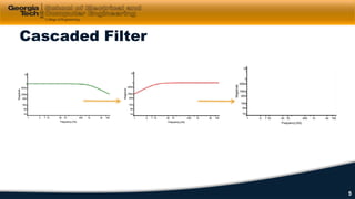

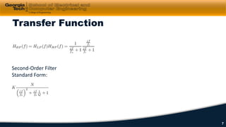


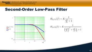


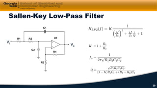


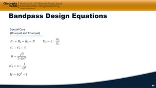


This document discusses cascaded first-order filters and second-order transfer functions for filters. It introduces cascaded filters and their characteristics. It then discusses second-order transfer functions, examining features like low-pass, high-pass, and band-pass filters. Finally, it introduces second-order Sallen-Key filter circuits and shows examples of designing low-pass, high-pass, and band-pass filters using these circuits.