Filters
Basic Realization & Circuit Design
Introduction of Filter
 Filter is a broad area of electronics also an
independent subject
 Oldest Technology: Filter with inductor &
capacitor called passive LC filter
 LC filter works well in high frequency
 Low frequency application : DC to 10 KHz
required inductors are bulky and provide
non ideal characteristics
 So, filter design without inductor is an
interesting issue
Introduction of Filter
 Passive LC Filter
 Active RC Filter
 Op-amp based RC filter
 Switch Capacitor Filter
FilterTransmission
 Filter transfer function
 Pass band: Passing signal whose frequency spectrum
lies within magnitude of transmission
 Stop band: Frequency band over which transmission is
zero
<Gain function>
<Attenuation function>
<Transfer function with phase>
<Transfer function >
Filter Types
Specifications for physical filter
circuit
 Physical circuit can not realize the idealized
characteristics
 Physical Circuit can not provide constant transmission
at all the pass band frequencies
 Also physical circuit can not provide zero transmission
at all the stop band frequencies i.e. some transmission
over stop band
 Transmission of physical circuit can not change abruptly
at the edge of the pass band.
 Transmission band extends from the pass band edge ωP
to stop band edge ωS.
 ωS /ωP is measured to understand the sharpness of
the low pass filter response called Selectivity Factor
Filter Specifications (Low pass)
Realistic specification for the transmission characteristics of
low pass filter
Maximum
deviation in
passband
transmission
Stop band signal
must be attenuated
by at least Amin
 Pass-band edge ωP
 Maximum allowed variation in pass-band transmission Amax
 Stop-band edge ωS
 Maximum required stop-band attenuation Amin
Towards Ideal Filter (Low Pass )
 Selectivity ratio ωS /ωP towards unity
 Lower Amax
 Higher Amin
 To achieve the above specification filter circuit should be
higher order and complex and expensive
 Filter design must be complicated if both the magnitude
and phase specified
 Ripple peak at pass band as well as stop band must be
equal called equi-ripple characteristics
Filter Transfer function
The degree of the denominator, N, is the filter order
For the filter circuit to be stable, the degree of the numerator must
be less than or equal to that of the denominator M ≤ N
Numerator and denominator coefficients, a0, a1, . . . , aM and b0, b1, . . . ,
bN−1, are real numbers.
The numerator roots, z1, z2, . . . , zM, are the transfer function
zeros, or transmission zeros
Denominator roots, p1, p2, . . . , pN, are the transfer function poles,
or the natural modes
Each transmission zero or pole can be either a real or a complex
number
Complex zeros and poles, however, must occur in conjugate pairs.
(1)
(2)
Filter transfer function (LP)- ‘Zeros’
Zeros are usually placed on the jω axis at stopband frequencies
Infinite attenuation (zero transmission) at two stopband frequencies:
ωl1 and ωl2.
The filter then must have transmission zeros at s = +j ωl1 and s =
+jωl2
Since complex zeros occur in conjugate pairs, there must also be
transmission zeros at s = −j ωl1 and s = −j ωl2.
Thus the numerator polynomial of this filter will have the factors
(s + j ωl1)(s − j ωl1)(s + j ωl2)(s − j ωl2)
Can be written as (s2 + ωl1
2)(s2 + ωl2
2) If, S=jω, then ω=ωl1 &
ω=ωl2
Filter transfer function (LP)- ‘Zeros’
 Transmission decreases toward -∞ as ω approaches ∞.
 Thus the filter must have one or more transmission zeros at s
= ∞.
 Number of transmission zeros at s = ∞ is the difference
between the degree of the numerator polynomial, M, and the
degree of the denominator polynomial, N, of the transfer
function
 N − M zeros at s = ∞
Filter transfer function (LP)- ‘Poles’
For a filter circuit to be stable,
all its poles must lie in the left
half of the s plane, and thus p1,
p2, . . . , pN must all have negative
real parts.
Assumed that filter is of fifth
order (N = 5).
Two pairs of complex-conjugate
poles and one real-axis pole, for
a total of five poles.
All the poles lie in the passband
that gives the filter its high
transmission at passband
frequencies.
The five transmission zeros are
at s = ∞, ± j ωl1, ±jωl2,
Filter Transfer function (BP)
Bandpass filter
Transmission zeros are at s = ± j ωl1
and S=±jωl2
one or more zeros at s = 0 and one
or more zeros at s = ∞ because the
transmission decreases toward 0 as
ω approaches 0 and ∞
Assuming that only one zero exists
at each of s = 0 and s = ∞, the filter
must be of sixth order
Transfer function (All Pole Filter)
Low-pass filter
No finite values of ω at which the
attenuation is infinite (zero
transmission).
Thus it is possible that all the
transmission zeros of this filter are
at s = ∞.
All-pole filter
Problem 1
A second order filter has its poles at s = [-1/2 ±j(√3/2)].
The transmission is zero at w=2 rad/s and is unity at DC
(w=0). Find the transfer function
Problem 2
A forth order filter has zero transmission at w=0, w=2 rad/s
and w=∞. The natural modes are -0.1±j0.8 and -0.1±j1.2 find
T(s).
Filter Approximations
Butterworth Approximation: Maximally flat
response in pass band.
Chebyshev Approximation: Pass band ripple
and sharp cut-off.
Elliptical Approximation: Pass band and stop
band ripple and very sharp cut-off
Bessel Approximation: No signal distortion in
pass band.
Filter Approximations
Butterworth Filter
 Flat pass band.
 This filter exhibits a monotonically decreasing transmission with
all the transmission zeros at ω = ∞
 All-pole filter
 Design specifications:
• Amax
• passband edge ωp
• Amin
• stop band edge ωS
ℇ:To determine maximum
deviation in pass band
Butterworth Filter
 Fix the value of ℇ,
for Amax=3 dB, ℇ=1
Amax
 Fix the order N for A(ωs)≥Amin
ωS
Amin
Butterworth Filter
The degree of passband flatness increases as the order N is
increased
N is increased the filter response approaches the ideal brick-
wall type of response
DC Gain normalized at 1
Butterworth Filter: Graphical
Construction
The natural modes of an Nth-order Butterworth filter can
be determined from the graphical construction
Natural modes lie on a circle of radius ω0 = ωp(1/ε)1/N
Spaced by equal angles of (П/N)
First mode at an angle (П/2N) from the +jω axis
P1, P2…PN are poles, K is setting any DC gain
Graphical construction for determining
the poles of Butterworth Filter
Graphical construction for determining
the poles of Butterworth Filter
Problem 3
Find the Butterworth transfer function that meets the
following low-pass filter specifications: fp = 10 kHz, Amax = 1
dB, fs = 15 kHz, Amin = 25 dB, dc gain = 1.
Problem 3
Solution:
Amax = 1 dB; ε = 0.5088
If, N = 8, A( ωs) = 22.3 dB
If, N = 9 , A( ωs) = 25.8 dB. Select N = 9
The poles all have the same radius: ω0
=ωp(1/ε)1/N
ω0 = 6.773 × 10⁴ rad/s
p1 = ω0(−cos80° + j sin80°)
= ω0(−0.1736 + j0.9848)
First-Order and Second-Order
Filter Functions
Simplest filter transfer functions: first and second
order.
These functions are useful in the design of simple
filters. First- and second-order filters can also be
cascaded to realize a high-order filter.
Cascade design is one of the most popular
methods for the design of active filters (utilizing
op amps and RC circuits).
First Order Filter
 The general first-order transfer function is given by
 First-order filter with a natural mode at s = −ω0
 Transmission zero at s = -a0/a1
 High-frequency gain that approaches a1
 The numerator coefficients, a0 and a1, determine the type of
filter
 Active realizations provide considerably more versatility than
their passive counterparts; in many cases the gain can be set to
a desired value
 The output impedance of the active circuit very low, making
cascading easily possible.
 The op amp limits the high-frequency operation of the active
circuits.
Low pass (LP)
Bode Plot
Low pass (LP) with load
High pass (HP)
Bode Plot
High pass (HP)
High pass (HP)
General
General
All Pass Filter
An important special case of the first-order filter
function
Transmission zero and the natural mode are
symmetrically located relative to the jω axis
Transmission of the all-pass filter is (ideally) constant at
all frequencies
Phase shows frequency selectivity
All-pass filters are used as phase shifters and in
systems that require phase shaping
All Pass Filter
All Pass Filter
All Pass Filter

5 Filter Part 1 (16, 17, 18).pdf5 Filter Part 2 (Lecture 19, 20, 21, 22).pdf5 Filter Part 2 (Lecture 19, 20, 21, 22).pdf5 Filter Part 2 (Lecture 19, 20, 21, 22).pdf
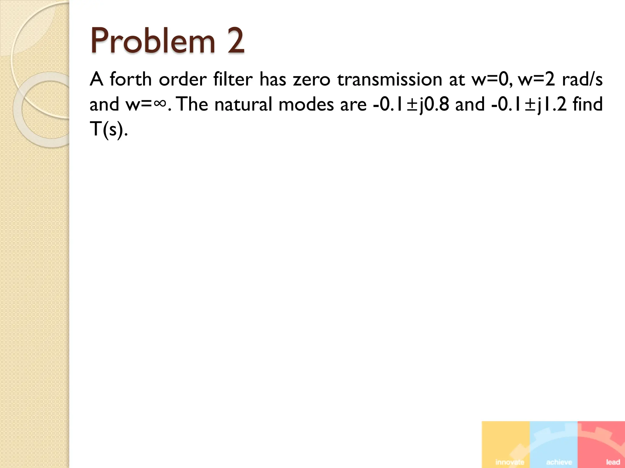
  • 1.
  • 2.
    Introduction of Filter Filter is a broad area of electronics also an independent subject  Oldest Technology: Filter with inductor & capacitor called passive LC filter  LC filter works well in high frequency  Low frequency application : DC to 10 KHz required inductors are bulky and provide non ideal characteristics  So, filter design without inductor is an interesting issue
  • 3.
    Introduction of Filter Passive LC Filter  Active RC Filter  Op-amp based RC filter  Switch Capacitor Filter
  • 4.
    FilterTransmission  Filter transferfunction  Pass band: Passing signal whose frequency spectrum lies within magnitude of transmission  Stop band: Frequency band over which transmission is zero <Gain function> <Attenuation function> <Transfer function with phase> <Transfer function >
  • 5.
  • 6.
    Specifications for physicalfilter circuit  Physical circuit can not realize the idealized characteristics  Physical Circuit can not provide constant transmission at all the pass band frequencies  Also physical circuit can not provide zero transmission at all the stop band frequencies i.e. some transmission over stop band  Transmission of physical circuit can not change abruptly at the edge of the pass band.  Transmission band extends from the pass band edge ωP to stop band edge ωS.  ωS /ωP is measured to understand the sharpness of the low pass filter response called Selectivity Factor
  • 7.
    Filter Specifications (Lowpass) Realistic specification for the transmission characteristics of low pass filter Maximum deviation in passband transmission Stop band signal must be attenuated by at least Amin  Pass-band edge ωP  Maximum allowed variation in pass-band transmission Amax  Stop-band edge ωS  Maximum required stop-band attenuation Amin
  • 8.
    Towards Ideal Filter(Low Pass )  Selectivity ratio ωS /ωP towards unity  Lower Amax  Higher Amin  To achieve the above specification filter circuit should be higher order and complex and expensive  Filter design must be complicated if both the magnitude and phase specified  Ripple peak at pass band as well as stop band must be equal called equi-ripple characteristics
  • 9.
    Filter Transfer function Thedegree of the denominator, N, is the filter order For the filter circuit to be stable, the degree of the numerator must be less than or equal to that of the denominator M ≤ N Numerator and denominator coefficients, a0, a1, . . . , aM and b0, b1, . . . , bN−1, are real numbers. The numerator roots, z1, z2, . . . , zM, are the transfer function zeros, or transmission zeros Denominator roots, p1, p2, . . . , pN, are the transfer function poles, or the natural modes Each transmission zero or pole can be either a real or a complex number Complex zeros and poles, however, must occur in conjugate pairs. (1) (2)
  • 10.
    Filter transfer function(LP)- ‘Zeros’ Zeros are usually placed on the jω axis at stopband frequencies Infinite attenuation (zero transmission) at two stopband frequencies: ωl1 and ωl2. The filter then must have transmission zeros at s = +j ωl1 and s = +jωl2 Since complex zeros occur in conjugate pairs, there must also be transmission zeros at s = −j ωl1 and s = −j ωl2. Thus the numerator polynomial of this filter will have the factors (s + j ωl1)(s − j ωl1)(s + j ωl2)(s − j ωl2) Can be written as (s2 + ωl1 2)(s2 + ωl2 2) If, S=jω, then ω=ωl1 & ω=ωl2
  • 11.
    Filter transfer function(LP)- ‘Zeros’  Transmission decreases toward -∞ as ω approaches ∞.  Thus the filter must have one or more transmission zeros at s = ∞.  Number of transmission zeros at s = ∞ is the difference between the degree of the numerator polynomial, M, and the degree of the denominator polynomial, N, of the transfer function  N − M zeros at s = ∞
  • 12.
    Filter transfer function(LP)- ‘Poles’ For a filter circuit to be stable, all its poles must lie in the left half of the s plane, and thus p1, p2, . . . , pN must all have negative real parts. Assumed that filter is of fifth order (N = 5). Two pairs of complex-conjugate poles and one real-axis pole, for a total of five poles. All the poles lie in the passband that gives the filter its high transmission at passband frequencies. The five transmission zeros are at s = ∞, ± j ωl1, ±jωl2,
  • 13.
  • 14.
  • 15.
    Filter Transfer function(BP) Bandpass filter Transmission zeros are at s = ± j ωl1 and S=±jωl2 one or more zeros at s = 0 and one or more zeros at s = ∞ because the transmission decreases toward 0 as ω approaches 0 and ∞ Assuming that only one zero exists at each of s = 0 and s = ∞, the filter must be of sixth order
  • 16.
    Transfer function (AllPole Filter) Low-pass filter No finite values of ω at which the attenuation is infinite (zero transmission). Thus it is possible that all the transmission zeros of this filter are at s = ∞. All-pole filter
  • 17.
    Problem 1 A secondorder filter has its poles at s = [-1/2 ±j(√3/2)]. The transmission is zero at w=2 rad/s and is unity at DC (w=0). Find the transfer function
  • 18.
    Problem 2 A forthorder filter has zero transmission at w=0, w=2 rad/s and w=∞. The natural modes are -0.1±j0.8 and -0.1±j1.2 find T(s).
  • 19.
    Filter Approximations Butterworth Approximation:Maximally flat response in pass band. Chebyshev Approximation: Pass band ripple and sharp cut-off. Elliptical Approximation: Pass band and stop band ripple and very sharp cut-off Bessel Approximation: No signal distortion in pass band.
  • 20.
  • 21.
    Butterworth Filter  Flatpass band.  This filter exhibits a monotonically decreasing transmission with all the transmission zeros at ω = ∞  All-pole filter  Design specifications: • Amax • passband edge ωp • Amin • stop band edge ωS ℇ:To determine maximum deviation in pass band
  • 22.
    Butterworth Filter  Fixthe value of ℇ, for Amax=3 dB, ℇ=1 Amax  Fix the order N for A(ωs)≥Amin ωS Amin
  • 23.
    Butterworth Filter The degreeof passband flatness increases as the order N is increased N is increased the filter response approaches the ideal brick- wall type of response DC Gain normalized at 1
  • 24.
    Butterworth Filter: Graphical Construction Thenatural modes of an Nth-order Butterworth filter can be determined from the graphical construction Natural modes lie on a circle of radius ω0 = ωp(1/ε)1/N Spaced by equal angles of (П/N) First mode at an angle (П/2N) from the +jω axis P1, P2…PN are poles, K is setting any DC gain
  • 25.
    Graphical construction fordetermining the poles of Butterworth Filter
  • 26.
    Graphical construction fordetermining the poles of Butterworth Filter
  • 27.
    Problem 3 Find theButterworth transfer function that meets the following low-pass filter specifications: fp = 10 kHz, Amax = 1 dB, fs = 15 kHz, Amin = 25 dB, dc gain = 1.
  • 28.
    Problem 3 Solution: Amax =1 dB; ε = 0.5088 If, N = 8, A( ωs) = 22.3 dB If, N = 9 , A( ωs) = 25.8 dB. Select N = 9 The poles all have the same radius: ω0 =ωp(1/ε)1/N ω0 = 6.773 × 10⁴ rad/s p1 = ω0(−cos80° + j sin80°) = ω0(−0.1736 + j0.9848)
  • 29.
    First-Order and Second-Order FilterFunctions Simplest filter transfer functions: first and second order. These functions are useful in the design of simple filters. First- and second-order filters can also be cascaded to realize a high-order filter. Cascade design is one of the most popular methods for the design of active filters (utilizing op amps and RC circuits).
  • 30.
    First Order Filter The general first-order transfer function is given by  First-order filter with a natural mode at s = −ω0  Transmission zero at s = -a0/a1  High-frequency gain that approaches a1  The numerator coefficients, a0 and a1, determine the type of filter  Active realizations provide considerably more versatility than their passive counterparts; in many cases the gain can be set to a desired value  The output impedance of the active circuit very low, making cascading easily possible.  The op amp limits the high-frequency operation of the active circuits.
  • 31.
  • 32.
    Low pass (LP)with load
  • 33.
    Low pass (LP)with load
  • 34.
  • 35.
  • 36.
  • 37.
  • 38.
  • 39.
    All Pass Filter Animportant special case of the first-order filter function Transmission zero and the natural mode are symmetrically located relative to the jω axis Transmission of the all-pass filter is (ideally) constant at all frequencies Phase shows frequency selectivity All-pass filters are used as phase shifters and in systems that require phase shaping
  • 40.
  • 41.
  • 42.