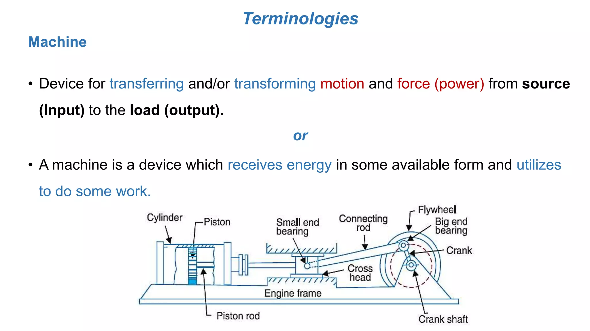
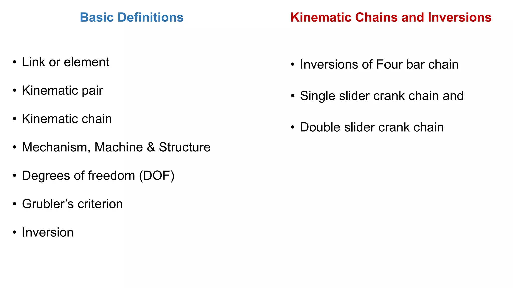
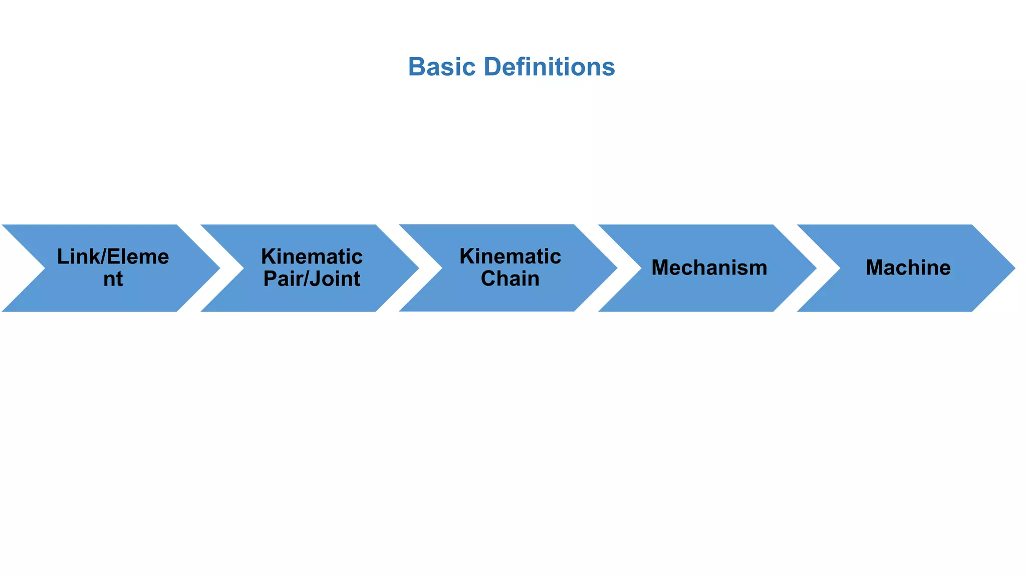
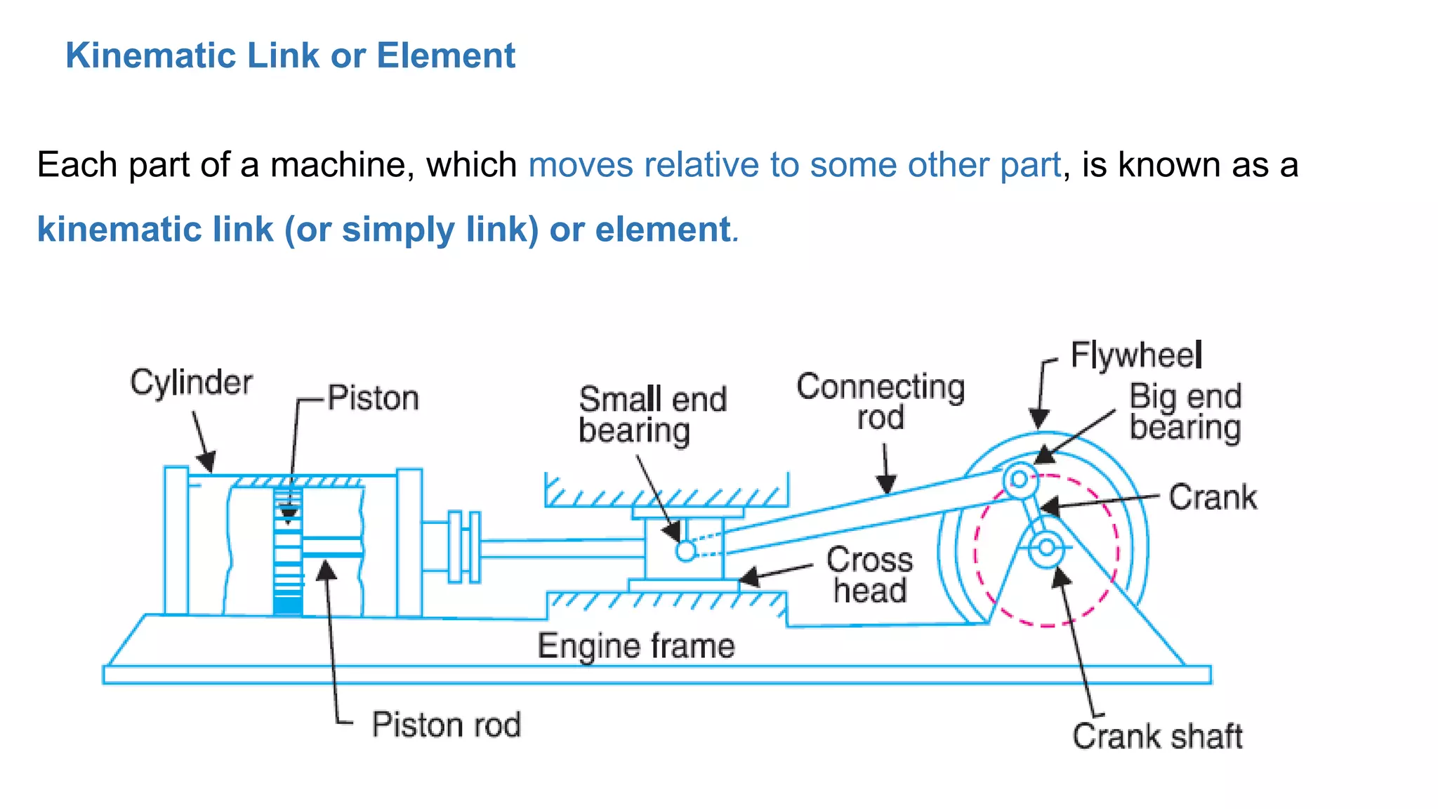
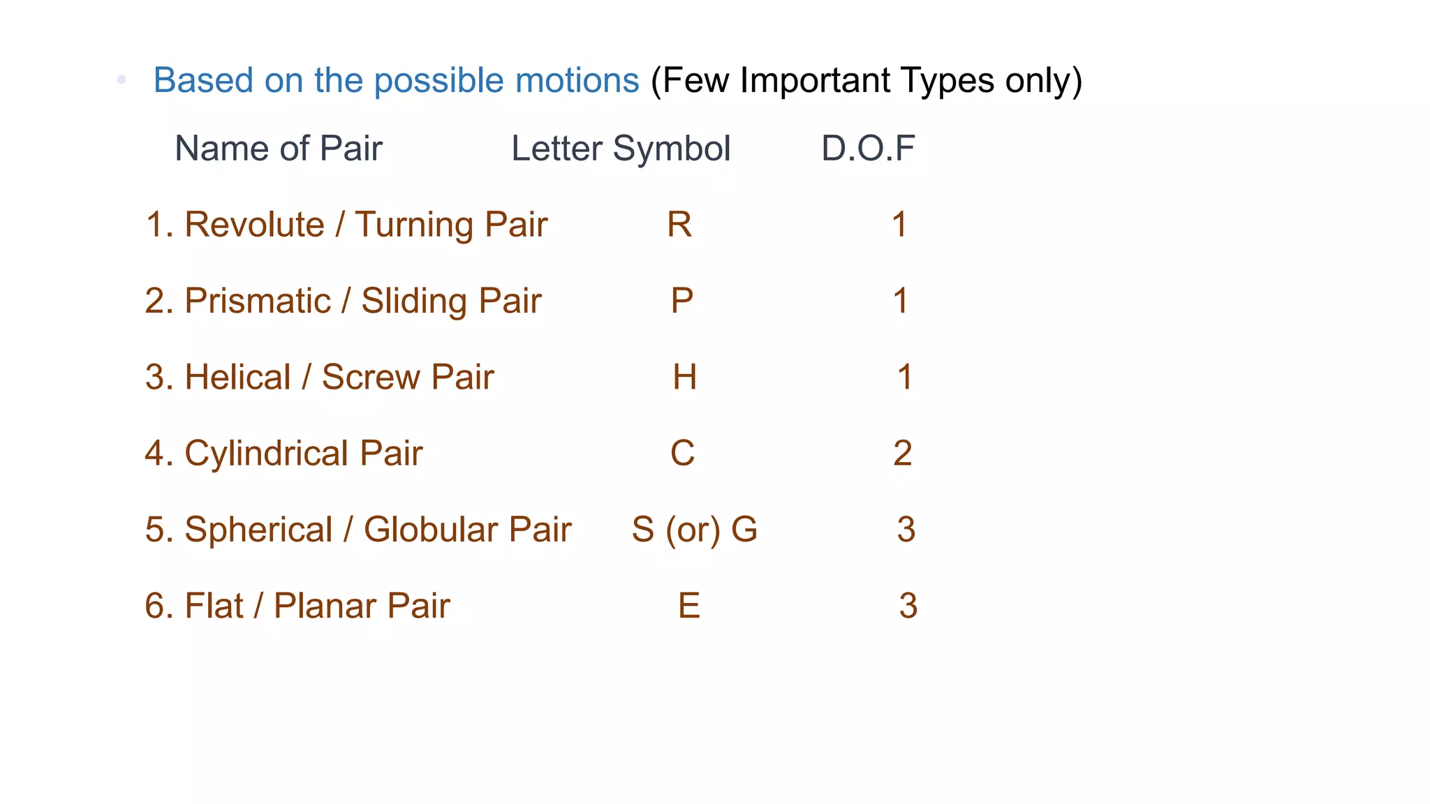
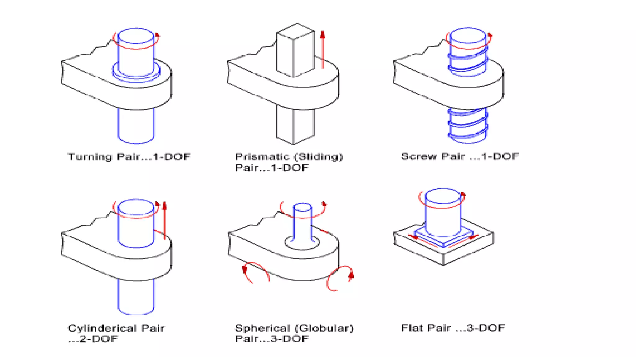
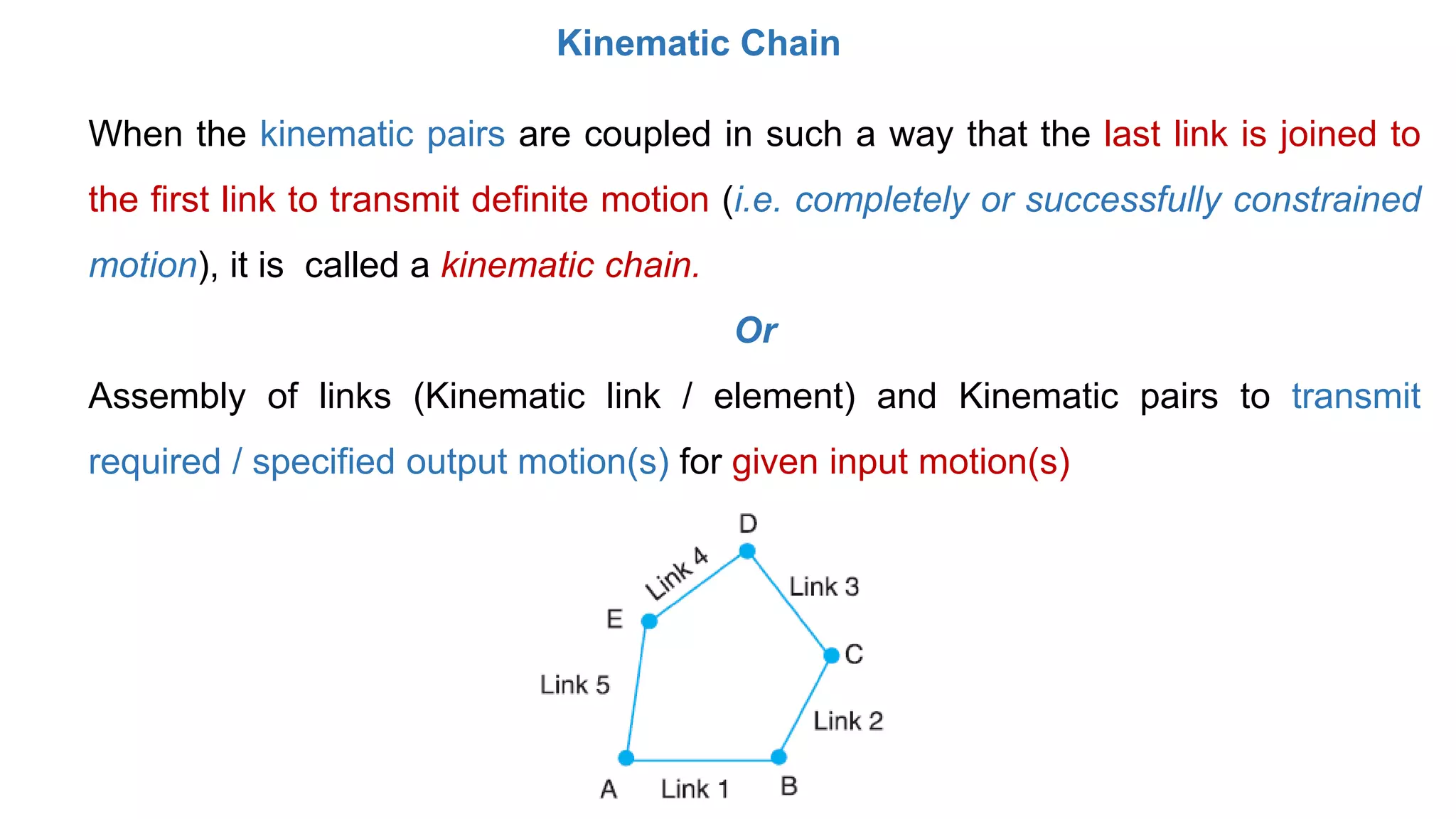
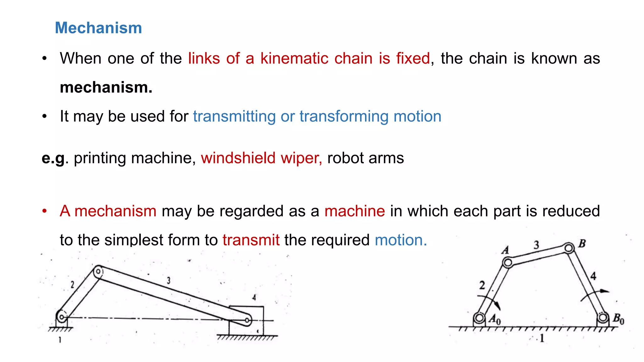
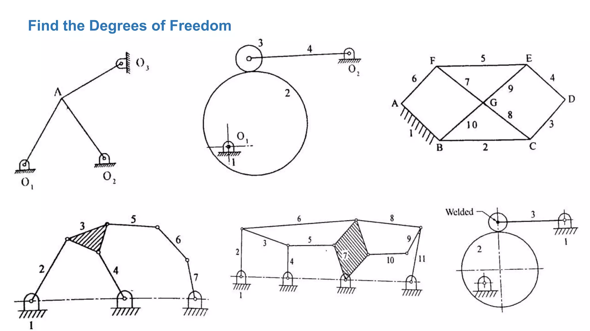
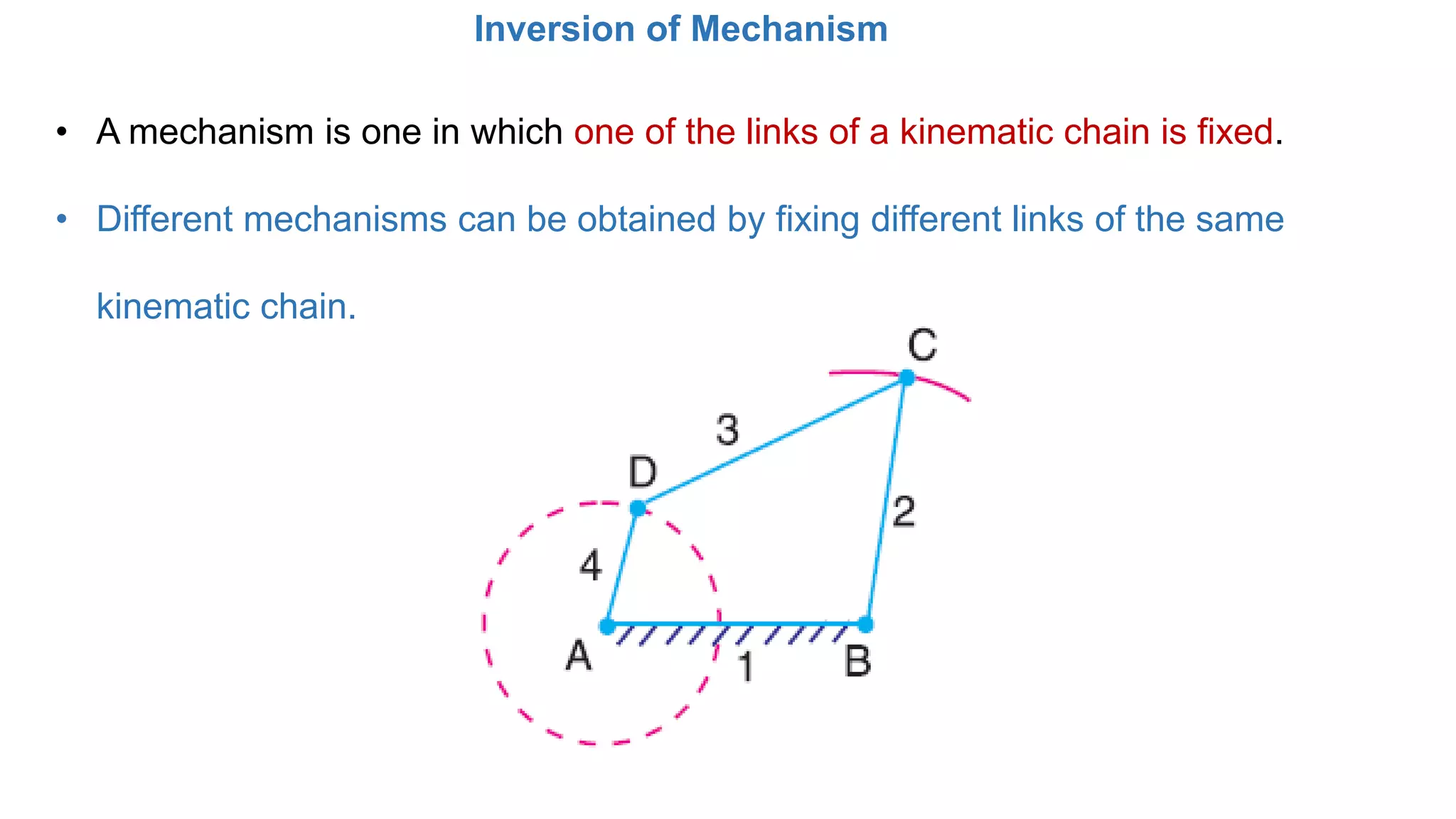
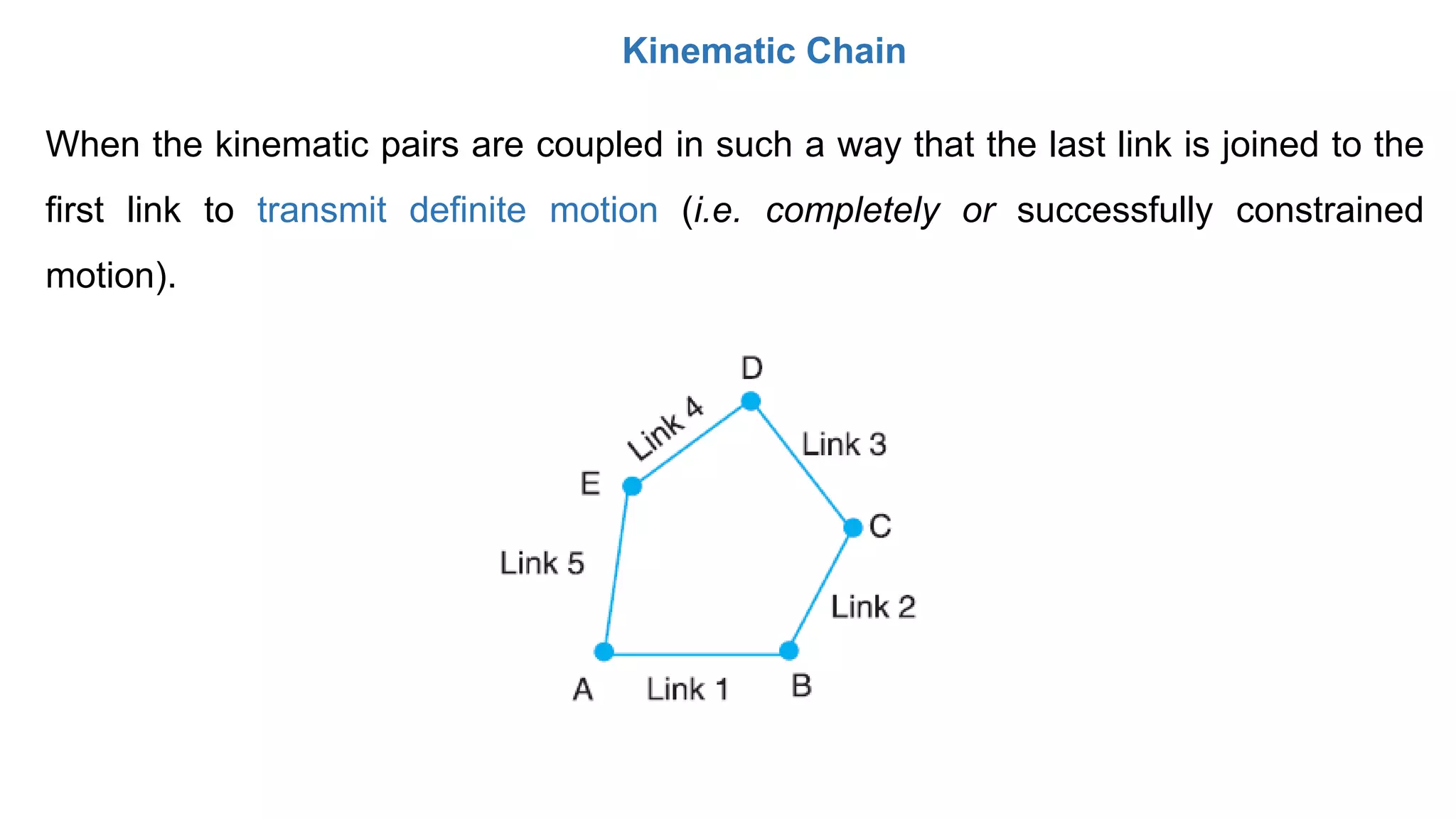
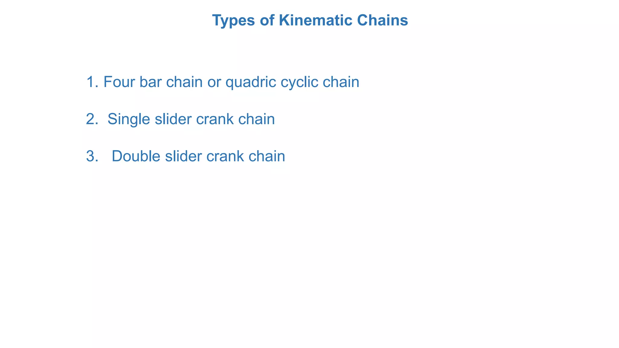
This document provides information about the Kinematics of Machines course offered by the Department of Mechanical Engineering at JSS Academy of Technical Education in Bangalore, India. It lists the course code, textbooks, reference books, course outcomes, and chapter topics that will be covered. The topics include basic definitions related to kinematic elements, pairs, chains, and mechanisms. It describes types of kinematic pairs and chains, including four-bar chains, single slider-crank chains, and double slider-crank chains. It also covers degrees of freedom, Grubler's criterion, and inversions of mechanisms.
Unit 1 – Basics of Mechanics
Topics to be covered – unit1
Basic kinematic concepts and definitions
Degree of freedom & Mobility
Kutzbach criterion & Gruebler’s criterion
Grashof’s Law
Kinematic inversions of four-bar-chain and slider crank chains – Limit positions
Mechanical advantage – Transmission Angle
Classification of mechanisms
Description of some common mechanisms
Unit 7-gear trains, Kinematics of machines of VTU Syllabus prepared by Hareesha N Gowda, Asst. Prof, Dayananda Sagar College of Engg, Blore. Please write to hareeshang@gmail.com for suggestions and criticisms.
This slide includes the following topics:
classification of mechanisms – Basic kinematic concepts and definitions – Degree of freedom, Mobility – Kutzbach criterion, Gruebler’s criterion – Grashof’s Law – Kinematic inversions of four-bar chain and slider crank chains – Limit positions – Mechanical advantage – Transmission Angle – Description of some common mechanisms – Quick return mechanisms, Straight line generators, Universal Joint.
Surface roughness metrology deals with basic terminology of surface,surface roughness indication methods,analysis of surface traces, measurement methods,surface roughness measuring instruments such as Stylus Probe Instrument, Profilometer, Tomlinson Surface Meter ,The Taylor-Hobson Talysurf etc.This is very useful for diploma,degree engineering students of mechanical,production,automobile branch
Like Comment and download
Belt is a Flexible Mechanical element that transmit power from one shaft to another
Gear Train
Ex: Automobile, engines etc.
Chain Drive
Ex : Bi-cycle , Motor cycle etc.
Belt Drive
Ex: Rice mills, sewing machine etc.
Rope Drive
Ex: lift, crane etc
A tool that has a single point for cutting purpose is called single point cutting tool. It is generally used in the lathe machine, shaper machine etc. It is used to remove the materials from the workpiece.
The basic of KOM is include “Mechanisms” and “Machines”. The word Mechanism has many meanings. In kinematics, a mechanism is a means of transmitting, controlling, or constraining relative movement .
Unit 1-introduction to Mechanisms, Kinematics of machines of VTU Syllabus prepared by Hareesha N Gowda, Asst. Prof, Dayananda Sagar College of Engg, Blore. Please write to hareeshang@gmail.com for suggestions and criticisms.
THEORY OF MACHINES FOR VTU, AMIE, DME STUDENTS..
The study of a mechanism involves its analysis as well as synthesis.
Analysis is the study of motions and forces concerning different parts
of an existing mechanism. Whereas Synthesis involves the design of its
different parts.
Mechanics: It is that branch of scientific analysis which deals with
motion, time and force.
Kinematics is the study of motion, without considering the forces
which produce that motion. Kinematics of machines deals with the
study of the relative motion of machine parts. It involves the study of
position, displacement, velocity and acceleration of machine parts.
Dynamics of machines involves the study of forces acting on the
machine parts and the motions resulting from these forces.
Plane motion: A body has plane motion, if all its points move in
planes which are parallel to some reference plane. A body with plane
motion will have only three degrees of freedom. i.e., linear along two
axes parallel to the reference plane and rotational/angular about the
axis perpendicular to the reference plane. (eg. linear along X and Z
and rotational about Y.)The reference plane is called plane of motion.
Plane motion can be of three types. 1) Translation 2) rotation and 3)
combination of translation and rotation.
Translation: A body has translation if it moves so that all straight
lines in the body move to parallel positions. Rectilinear translation is a
motion wherein all points of the body move in straight lie paths.
Eg. The slider in slider crank mechanism has rectilinear translation.
Kinematic link, Types of links, Kinematic pair, Types of constrained motions, Types of Kinematic pairs, Kinematic chain, Types of joints, Mechanism, Machine, Degree of freedom, Mobility of Mechanism, Inversion, Grashoff’s law, Four-Bar Chain and its Inversions, Slider crank Chain and its Inversions, Double slider crank Chain and its Conversions, Mechanisms with Higher pairs, Equivalent Linkages and its Cases - Sliding Pairs in Place of Turning Pairs, Spring in Place of Turning Pairs, Cam Pair in Place of Turning Pairs
Introduction_Medical Robotics
Types of medical robots - Navigation - Motion Replication - Imaging - Rehabilitation and Prosthetics - State of art of robotics in the field of healthcare
Introduction to OS
Basic Principles, Operating System Structures, System Calls & Types, Processes: Concept Scheduling - Inter
Process Communication, Introduction to Distributed Operating System, Types of network based OS.
Robot Drives And End Effectors
Robot drive systems: Hydraulic, Pneumatic and Electric drive
systems, classification of end effectors, mechanical grippers, vacuum grippers, magnetic grippers,
adhesive gripper, gripper force analysis and gripper design
Robot Anatomy And Motion Analysis
Anatomy of a Robot, Robot configurations: polar, cylindrical,
Cartesian, and jointed arm configurations, Robot links and joints, Degrees of freedom: types of
movements, vertical, radial and rotational traverse, roll, pitch and yaw, Wok volume/envelope, Robot
kinematics: Introduction to direct and inverse kinematics, transformations and rotation matrix
Avoiding Risk & Harmful Habits
Characteristics of health compromising behaviors, Recognizing and avoiding of
addictions, How addiction develops, Types of addictions, influencing factors of addictions, Differences between addictive
people and non addictive people & their behaviors. Effects of addictions
Creating Healthy & Caring Relationships
Building communication skills, Friends and friendship - Education,
the value of relationship and communication skills, Relationships for Better or worsening of life, understanding of basic
instincts of life (more than a biology), Changing health behaviours through social engineering
Building Healthy Life Style for Better Future.pptxtaruian
Building Healthy Life Style for Better Future
Developing healthy diet for good health, Food & health, Nutritional
guidelines for good health, Obesity & overweight disorders and its management, Eating disorders, Fitness components for
health, Wellness and physical function, How to avoid exercise injuries
Good Health & It’s balance for positive mindset.pptxtaruian
Health -Importance of Health, Influencing factors of Health,
Health beliefs, Advantages of good health, Health & Behavior, Health & Society, Health & family, Health & Personality,
Psychological disorders-Methods to improve good psychological health, Changing health habits for good health
Thread terminology, sectional views of threads. ISO Metric (Internal & External), BSW (Internal & External), Square and Acme, Sellers thread, American Standard thread.
IoT Processing Topologies and Types: Data Format, Importance of Processing in IoT, Processing Topologies, IoT Device Design and Selection Considerations, Processing Offloading.
Introduction to IoT (Basics of Networking & Emergence of IoT).pptxtaruian
Basics of Networking: Introduction, Network Types, Layered network models.
Emergence of IoT: Introduction, Evolution of IoT, Enabling IoT and the Complex Interdependence of Technologies, IoT Networking Components.
About
Indigenized remote control interface card suitable for MAFI system CCR equipment. Compatible for IDM8000 CCR. Backplane mounted serial and TCP/Ethernet communication module for CCR remote access. IDM 8000 CCR remote control on serial and TCP protocol.
• Remote control: Parallel or serial interface.
• Compatible with MAFI CCR system.
• Compatible with IDM8000 CCR.
• Compatible with Backplane mount serial communication.
• Compatible with commercial and Defence aviation CCR system.
• Remote control system for accessing CCR and allied system over serial or TCP.
• Indigenized local Support/presence in India.
• Easy in configuration using DIP switches.
Technical Specifications
Indigenized remote control interface card suitable for MAFI system CCR equipment. Compatible for IDM8000 CCR. Backplane mounted serial and TCP/Ethernet communication module for CCR remote access. IDM 8000 CCR remote control on serial and TCP protocol.
Key Features
Indigenized remote control interface card suitable for MAFI system CCR equipment. Compatible for IDM8000 CCR. Backplane mounted serial and TCP/Ethernet communication module for CCR remote access. IDM 8000 CCR remote control on serial and TCP protocol.
• Remote control: Parallel or serial interface
• Compatible with MAFI CCR system
• Copatiable with IDM8000 CCR
• Compatible with Backplane mount serial communication.
• Compatible with commercial and Defence aviation CCR system.
• Remote control system for accessing CCR and allied system over serial or TCP.
• Indigenized local Support/presence in India.
Application
• Remote control: Parallel or serial interface.
• Compatible with MAFI CCR system.
• Compatible with IDM8000 CCR.
• Compatible with Backplane mount serial communication.
• Compatible with commercial and Defence aviation CCR system.
• Remote control system for accessing CCR and allied system over serial or TCP.
• Indigenized local Support/presence in India.
• Easy in configuration using DIP switches.
CFD Simulation of By-pass Flow in a HRSG module by R&R Consult.pptxR&R Consult
CFD analysis is incredibly effective at solving mysteries and improving the performance of complex systems!
Here's a great example: At a large natural gas-fired power plant, where they use waste heat to generate steam and energy, they were puzzled that their boiler wasn't producing as much steam as expected.
R&R and Tetra Engineering Group Inc. were asked to solve the issue with reduced steam production.
An inspection had shown that a significant amount of hot flue gas was bypassing the boiler tubes, where the heat was supposed to be transferred.
R&R Consult conducted a CFD analysis, which revealed that 6.3% of the flue gas was bypassing the boiler tubes without transferring heat. The analysis also showed that the flue gas was instead being directed along the sides of the boiler and between the modules that were supposed to capture the heat. This was the cause of the reduced performance.
Based on our results, Tetra Engineering installed covering plates to reduce the bypass flow. This improved the boiler's performance and increased electricity production.
It is always satisfying when we can help solve complex challenges like this. Do your systems also need a check-up or optimization? Give us a call!
Work done in cooperation with James Malloy and David Moelling from Tetra Engineering.
More examples of our work https://www.r-r-consult.dk/en/cases-en/
Explore the innovative world of trenchless pipe repair with our comprehensive guide, "The Benefits and Techniques of Trenchless Pipe Repair." This document delves into the modern methods of repairing underground pipes without the need for extensive excavation, highlighting the numerous advantages and the latest techniques used in the industry.
Learn about the cost savings, reduced environmental impact, and minimal disruption associated with trenchless technology. Discover detailed explanations of popular techniques such as pipe bursting, cured-in-place pipe (CIPP) lining, and directional drilling. Understand how these methods can be applied to various types of infrastructure, from residential plumbing to large-scale municipal systems.
Ideal for homeowners, contractors, engineers, and anyone interested in modern plumbing solutions, this guide provides valuable insights into why trenchless pipe repair is becoming the preferred choice for pipe rehabilitation. Stay informed about the latest advancements and best practices in the field.
Student information management system project report ii.pdfKamal Acharya
Our project explains about the student management. This project mainly explains the various actions related to student details. This project shows some ease in adding, editing and deleting the student details. It also provides a less time consuming process for viewing, adding, editing and deleting the marks of the students.
Welcome to WIPAC Monthly the magazine brought to you by the LinkedIn Group Water Industry Process Automation & Control.
In this month's edition, along with this month's industry news to celebrate the 13 years since the group was created we have articles including
A case study of the used of Advanced Process Control at the Wastewater Treatment works at Lleida in Spain
A look back on an article on smart wastewater networks in order to see how the industry has measured up in the interim around the adoption of Digital Transformation in the Water Industry.
Quality defects in TMT Bars, Possible causes and Potential Solutions.PrashantGoswami42
Maintaining high-quality standards in the production of TMT bars is crucial for ensuring structural integrity in construction. Addressing common defects through careful monitoring, standardized processes, and advanced technology can significantly improve the quality of TMT bars. Continuous training and adherence to quality control measures will also play a pivotal role in minimizing these defects.
Water scarcity is the lack of fresh water resources to meet the standard water demand. There are two type of water scarcity. One is physical. The other is economic water scarcity.
Immunizing Image Classifiers Against Localized Adversary Attacksgerogepatton
This paper addresses the vulnerability of deep learning models, particularly convolutional neural networks
(CNN)s, to adversarial attacks and presents a proactive training technique designed to counter them. We
introduce a novel volumization algorithm, which transforms 2D images into 3D volumetric representations.
When combined with 3D convolution and deep curriculum learning optimization (CLO), itsignificantly improves
the immunity of models against localized universal attacks by up to 40%. We evaluate our proposed approach
using contemporary CNN architectures and the modified Canadian Institute for Advanced Research (CIFAR-10
and CIFAR-100) and ImageNet Large Scale Visual Recognition Challenge (ILSVRC12) datasets, showcasing
accuracy improvements over previous techniques. The results indicate that the combination of the volumetric
input and curriculum learning holds significant promise for mitigating adversarial attacks without necessitating
adversary training.
Democratizing Fuzzing at Scale by Abhishek Aryaabh.arya
Presented at NUS: Fuzzing and Software Security Summer School 2024
This keynote talks about the democratization of fuzzing at scale, highlighting the collaboration between open source communities, academia, and industry to advance the field of fuzzing. It delves into the history of fuzzing, the development of scalable fuzzing platforms, and the empowerment of community-driven research. The talk will further discuss recent advancements leveraging AI/ML and offer insights into the future evolution of the fuzzing landscape.
Design and Analysis of Algorithms-DP,Backtracking,Graphs,B&B
Module 1 introduction to kinematics of machinery
1. Department of Mechanical Engineering
JSS Academy of Technical Education, Bangalore-560060
Kinematics of Machines
(Course Code:17ME42)
2. TEXT BOOKS
Theory of Machines, Rattan S.S, Tata McGraw-Hill Publishing Company.
Theory of Machines, Sadhu Singh
Theory of Machines, by R S Khurmi
REFERENCE BOOKS:
“Theory of Machines & Mechanisms", J.J. Uicker, , G.R. Pennock, J.E. Shigley. OXFORD 3rd Ed.
Further Reference:
National Programme on Technology Enhanced Learning (NPTEL)
http://nptel.ac.in/courses/112104121/1
3. At the end of the course, students will be able to,
CO1: Describe the concepts of machines, mechanisms and related terminologies.
CO2: Identify the mechanisms and predict their motions in mechanical components.
CO3: Analyze planar mechanism for displacement, velocity and acceleration analytically and
graphically .
CO4: Analyze various motion transmission elements like gears, gear trains and cams.
CO5: Utilize analytical, mathematical and graphical aspects of kinematics of machines for
effective design.
Course Outcomes
5. Module 1
Introduction: Definitions Link or element, kinematic pairs, Degrees of freedom, Grubler's
criterion (without derivation), Kinematic chain, Mechanism, Structure, Mobility of Mechanism,
Inversion, Machine.
Kinematic Chains and Inversions: Inversions of Four bar chain; Single slider crank chain
and Double slider crank chain
6. Terminologies
Machine
• Device for transferring and/or transforming motion and force (power) from source
(Input) to the load (output).
or
• A machine is a device which receives energy in some available form and utilizes
to do some work.
8. Basic Definitions
• Link or element
• Kinematic pair
• Kinematic chain
• Mechanism, Machine & Structure
• Degrees of freedom (DOF)
• Grubler’s criterion
• Inversion
Kinematic Chains and Inversions
• Inversions of Four bar chain
• Single slider crank chain and
• Double slider crank chain
10. Kinematic Link or Element
Each part of a machine, which moves relative to some other part, is known as a
kinematic link (or simply link) or element.
11. Types of Links
• Rigid link : Link which does not undergo any deformation while transmitting motion.
• Flexible link: Link which is partly deformed in a manner not to affect the
transmission of motion.
e.g.: belts, ropes, chains and wires
• Fluid link: A link formed by having a fluid in a receptacle and the motion is
transmitted through the fluid by pressure.
e.g.: hydraulic presses, jacks and brakes.
12. Classification of Links
• Unary Link : Link with one Node (bucket of an excavator)
• Binary link : Link connected to other links at two points
• Ternary link: Link connected to other links at three points
• Quaternary link: Link connected to other links at four points
13. Structure
An assembly of a no. of resistant bodies (members) having no relative motion
between them and meant for carrying loads having straining action.
Examples: A railway bridge, a roof truss, machine frames. etc.
14. Difference Between a Machine and a Structure
• The parts of a machine move relative to one another, whereas the members of a
structure do not move relative to one another
• A machine transforms the available energy into some useful work, whereas in a
structure no energy is transformed into useful work
• The links of a machine may transmit both power and motion, while the members
of a structure transmit forces only (load bearing member).
15. Kinematic Pair
The two links or elements of a machine, when in contact with each other, are said to
form a pair, If the relative motion between them is completely or successfully
constrained (i.e. in a definite direction)
Successfully constrained
Completely constrained
16. 1. Completely constrained motion
When the motion between a pair is limited to a definite direction irrespective
of the direction of force applied, then the motion is said to be a completely
constrained motion.
Example:
The motion of a square bar in a square hole
The motion of a shaft with collars at each end in a circular hole
Constrained Motions
17. 2. Incompletely constrained motion
When the motion between a pair can take place in more than one direction,
then it can be an incompletely constrained motion.
E.g.: A circular bar or shaft in a circular hole
It may either rotate or slide in a hole. These both motions have no relationship
with the other (automobile wheel).
18. 3. Successfully constrained motion
When the motion between the elements, forming a pair, is such that the
constrained motion is not completed by itself, but by some other means
E.g.: Shaft in a foot-step bearing, I C engine valve, Piston inside an cylinder.
19. Classification of Kinematic Pairs
1. Sliding pair / Prismatic pair (P)
When the two elements of a pair are connected in
such a way that one can only slide relative to the
other, has a completely constrained motion.
E.g.: The piston and cylinder, Cross-head and guides of a
reciprocating steam engine, ram and its guides in shaper, tail
stock on the lathe bed
According to the type of relative motion between the elements
DOF = 1
20. 2. Turning Pair / Revolute Pair (R)
When the two elements of a pair are connected in such a way that one can only
turn or revolve about a fixed axis of another link.
Examples Lathe spindle supported in head stock.
cycle wheels turning over their axles.
DOF = 1
21. 3. Spherical pair (S)
When the two elements of a pair are connected in such a way that one element
turns or swivels about the other fixed element.
Eg: The ball and socket joint.
Attachment of a car mirror.
Pen stand.
DOF = 3
22. 4. Screw pair
When the two elements of a pair are connected in such a way that one element can
turn about the other by screw threads.
Examples:
• The lead screw of a lathe with nut
• Bolt with a nut
DOF = 1
23. 5. Cylindrical pair
If the relative motion between the pairing elements is the combination of turning
and sliding, then it is called as cylindrical pair.
DOF = 2
24. 6. Rolling Pair
When the two elements of a pair are connected in such a way that one rolls over
another fixed link.
E.g.: Ball and roller bearings, railway wheel rolling over a fixed rail
Belt and pulley
DOF = 1
25. According to the type / nature of contact between the elements / links.
Classification of Kinematic Pairs
1. Lower pair
When the two elements of a pair have a surface contact, and the surface of one
element slides or rolls over the surface of the other.
E.g. sliding pairs, turning pairs and screw pairs form lower pairs.
26. According to the type / nature of contact between the elements / links.
Classification of Kinematic Pairs
2. Higher pair
When the two elements of a pair have a line or point contact, and the motion
between the two elements is partly turning and partly sliding.
E.g.: toothed gearing, belt and rope drives, ball and roller bearings and cam and
follower.
27. According to the Mechanical arrangement.
1. Self closed pair
When the two elements of a pair are connected together mechanically in such a
way that only required relative motion occurs.
E.g. Lower pairs are self closed pair.
2. Force - closed pair
When the two elements of a pair are not connected
mechanically but are kept in contact by the action of
external forces, the pair is said to be a force-closed pair.
E.g.: Cam and follower
Classification of Kinematic Pairs
29. • Based on the possible motions (Few Important Types only)
Name of Pair Letter Symbol D.O.F
1. Revolute / Turning Pair R 1
2. Prismatic / Sliding Pair P 1
3. Helical / Screw Pair H 1
4. Cylindrical Pair C 2
5. Spherical / Globular Pair S (or) G 3
6. Flat / Planar Pair E 3
30.
31. Kinematic Chain
When the kinematic pairs are coupled in such a way that the last link is joined to
the first link to transmit definite motion (i.e. completely or successfully constrained
motion), it is called a kinematic chain.
Or
Assembly of links (Kinematic link / element) and Kinematic pairs to transmit
required / specified output motion(s) for given input motion(s)
32. Mechanism
• When one of the links of a kinematic chain is fixed, the chain is known as
mechanism.
• It may be used for transmitting or transforming motion
e.g. printing machine, windshield wiper, robot arms
• A mechanism may be regarded as a machine in which each part is reduced
to the simplest form to transmit the required motion.
33. Degrees of Freedom (DOF) / Mobility of a Mechanism
Number of independent coordinates, required to describe / specify the configuration
or position of all the links of the mechanism, with respect to the fixed link at any
given instant.
34. Degrees of freedom (DOF)
In a kinematic pair, depending on the constraints imposed on the motion, the links
may loose some of the six degrees of freedom.
35. Grubler’s Criterion / Equation
Grubler’s mobility equation
M = 3 (n-1) - j1 - j2
M = Mobility or Total no. of DOF
n = Total no. of links in a mechanism
J1 = No. of joints having 1 DOF
J2 = No. of joints having 2 DOF
If, M>0, It gives mechanism with M DOF
M=0, it gives a statically determinate structure
M<0, it gives statically indeterminate structure
38. Inversion of Mechanism
• A mechanism is one in which one of the links of a kinematic chain is fixed.
• Different mechanisms can be obtained by fixing different links of the same
kinematic chain.
39. Kinematic Chain
When the kinematic pairs are coupled in such a way that the last link is joined to the
first link to transmit definite motion (i.e. completely or successfully constrained
motion).
40. Types of Kinematic Chains
1. Four bar chain or quadric cyclic chain
2. Single slider crank chain
3. Double slider crank chain
41. 1. Four bar chain or quadric chain
• Four bar chain (mechanism) is the simplest and the
basic kinematic chain and consists of four rigid links
• Each of them forms a turning pair at A, B, C and D.
The link that makes a complete revolution is called a crank
• The four links may be of different lengths.
• According to Grashof ’s law for a four bar mechanism, “the sum of the
shortest and longest link lengths should not be greater than the sum of the
remaining two link lengths” if there is to be continuous relative motion between
the two links.
42. 1. Four bar chain or quadric chain
• The shortest link, will make a complete revolution relative to the other three links crank or driver.
In Fig., AD (link 4 ) is a crank.
• link BC (link 2) which makes a partial rotation or oscillates is known as lever or rocker or follower
• link CD (link 3) which connects the crank and lever is called connecting rod or coupler.
• The fixed link AB (link 1) is known as frame of the mechanism.
The mechanism transforms rotary motion into oscillating motion.
43.
44. • In this mechanism, the links AD and BC (having equal length) act as cranks and are connected to
the respective wheels.
• The link CD acts as a coupling rod.
• The link AB is fixed in order to maintain a constant centre to centre distance between them.
Purpose: Transmitting rotary motion from one wheel to the other wheel.
45.
46. Purpose of this mechanism is to convert rotary motion into reciprocating motion.
When the crank AB rotates about the fixed point A.
The lever oscillates about another fixed point D.
The end E of lever is connected to a piston rod which reciprocates in a cylinder.`
47. The four links are : fixed link at A, link AC, link CE and link BFD. Links CE and BFD act as levers.
On displacement of the mechanism, the tracing point E at
the end of the link CE traces out approximately a straight
line.
51. When the crank (link 2) is given a rotary motion, the connecting rod (link 3) oscillates
about a pin pivoted to the fixed link 4 at A. The piston attached to the piston rod (link
1) reciprocates.
Pendulum Pump or Bull Engine
52. Link 3 forming the turning pair is fixed and it corresponds to the connecting rod of a
reciprocating steam engine mechanism.
When the crank (link 2) rotates, the piston attached to piston rod (link 1)
reciprocates and the cylinder (link 4) oscillates about a pin pivoted to the fixed link
at A
A
53.
54. It consists of seven cylinders in one plane all revolve about fixed centre D.
Cylinders form link 1, Crank (link 2) is fixed. When the connecting rod (link4) rotates,
the piston (link 3) reciprocates inside the cylinder.
56. A mechanism used in shaping and slotting
machines, where the metal is cut intermittently.
• Link AC (i.e. link 3) is fixed.
• Crank CB revolves with uniform angular speed
about the fixed center C.
• Sliding block attached to the crank pin at B slides
along the slotted bar AP, thus causing AP to
oscillate about the pivoted point A.
• Short link PR transmits the motion from AP to the
ram which carries the tool and reciprocates along
the line of stroke R1R2
57. • The forward or cutting stroke occurs when the
crank rotates from the position CB1 to CB2 (or
through an angle β) in the clockwise direction.
• The return stroke occurs when the crank rotates
from the position CB2 to CB1 (or through angle
α) in the clockwise direction.
60. • This inversion is obtained by fixing the slotted plate (link 4).
• fixed plate or link 4 has two straight grooves cut in it, at right angles to each other.
• link 1 and link 3, are known as sliders and form sliding pairs with link 4.
• link AB (link 2) is a bar which forms turning pair with links 1 and 3.
• When the links 1 and 3 slide along their respective grooves, any point on the link 2 such as P traces
out an ellipse on the surface of link 4
61. Show that AP and BP are the semi-major axis and semi-minor axis of the ellipse.
OX and OY as horizontal and vertical axes
let the link BA is inclined at an angle θ with the horizontal,
Now the co-ordinates of the point P on the link BA will be
This is the equation of an ellipse
62. • This mechanism is used for converting rotary motion into a reciprocating motion.
• The inversion is obtained by fixing either the link 1 or link 3. link 1 is fixed.
• In this mechanism, when the link 2 (crank) rotates about B as centre, the link 4
(frame) reciprocates.
• The fixed link 1 guides the frame.