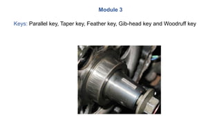
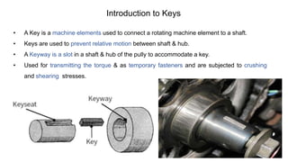
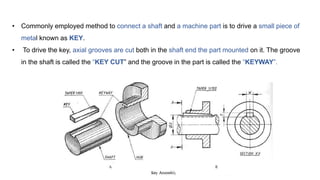
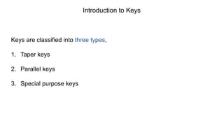
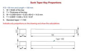
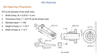
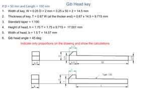
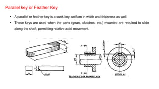
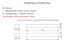
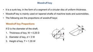
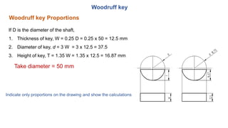
Department of Robotics & Automation
JSS Academy of Technical Education, Bangalore-560060
Robotics System Drawing & Standards
(Course Code:21RA35)
TEXT BOOKS
• Machine Drawing, K R Gopala Krishna, Subhash Publication, 2005.
• Machine Drawing, N D Bhat & V M Panchal, Charoratar publishing house, 2005.
Further Reference:
 National Programme on Technology Enhanced Learning (NPTEL)
https://nptel.ac.in/courses/112103019/
• To impart knowledge of thread forms, fasteners, keys, joints and couplings.
Course Learning Objectives
Module 3
Keys: Parallel key, Taper key, Feather key, Gib-head key and Woodruff key
• A Key is a machine elements used to connect a rotating machine element to a shaft.
• Keys are used to prevent relative motion between shaft & hub.
• A Keyway is a slot in a shaft & hub of the pully to accommodate a key.
• Used for transmitting the torque & as temporary fasteners and are subjected to crushing
and shearing stresses.
Introduction to Keys
• Commonly employed method to connect a shaft and a machine part is to drive a small piece of
metal known as KEY.
• To drive the key, axial grooves are cut both in the shaft end the part mounted on it. The groove
in the shaft is called the “KEY CUT” and the groove in the part is called the “KEYWAY”.
Keys are classified into three types,
1. Taper keys
2. Parallel keys
3. Special purpose keys
Introduction to Keys
Taper key
Sunk Taper Key
• A sunk taper key is of rectangular or square cross section of uniform width
having its bottom surface straight and top surface tapered.
If D is the diameter of the shaft in mm
1. W = Width of the key
2. T = Thickness of the key
3. W = 0.25D+2mm
4. T = 0.66W
5. Standard taper = 1:100
Sunk Taper key Proportions
Take diameter = 50 mm and Length = 100 mm
If D = 50 mm and Length = 100 mm
1. W = Width of the key
2. T = Thickness of the key
3. W = 0.25D+2mm = 0.25 x 60+2 = 14.5 mm
4. T = 0.66W = 0.66 x 14.5 = 9.57
5. Standard taper = 1:100
Indicate only proportions on the drawing and show the calculations
Sunk Taper Key Proportions
Gib Head key
If D is the diameter of the shaft, then,
1. Width of key, W = 0.25 D + 2 mm
2. Thickness of key, T = 0.67 W (at the thicker end)
3. Standard taper = 1:100
4. Height of head, h = 1.75 T
5. Width of head, b = 1.5 T
Gib Head Key Proportions
Gib Head key
If D = 50 mm and Length = 100 mm
1. Width of key, W = 0.25 D + 2 mm = 0.25 x 50 + 2 = 14.5 mm
2. Thickness of key, T = 0.67 W (at the thicker end) = 0.67 x 14.5 = 9.715 mm
3. Standard taper = 1:100
4. Height of head, h = 1.75 T = 1.75 x 9.715 = 17.001 mm
5. Width of head, b = 1.5 T = 14.57 mm
6. Gib head angle = 45 deg
Indicate only proportions on the drawing and show the calculations
Parallel key or Feather Key
• A parallel or feather key is a sunk key, uniform in width and thickness as well.
• These keys are used when the parts (gears, clutches, etc.) mounted are required to slide
along the shaft; permitting relative axial movement.
If D = 50 mm,
1. Width of key, W = 0.25 D + 2 mm = 14.5 mm
2. Thickness of key, T = 0.66 W = 9.57 mm
Parallel key or Feather Key
Take diameter = 50 mm and Length = 100 mm
Indicate only proportions on the drawing and show the calculations
• It is a sunk key, in the form of a segment of a circular disc of uniform thickness.
• Woodruff key is mainly used on tapered shafts of machine tools and automobiles.
• The following are the proportions of woodruff keys:
If D is the diameter of the shaft,
1. Thickness of key, W = 0.25 D
2. Diameter of key, d = 3 W
3. Height of key, T = 1.35 W
Woodruff key
Woodruff key Proportions
If D is the diameter of the shaft,
1. Thickness of key, W = 0.25 D = 0.25 x 50 = 12.5 mm
2. Diameter of key, d = 3 W = 3 x 12.5 = 37.5
3. Height of key, T = 1.35 W = 1.35 x 12.5 = 16.87 mm
Woodruff key
Woodruff key Proportions
Take diameter = 50 mm
Indicate only proportions on the drawing and show the calculations
End of Sheet

Keys.pptx

  • 1.
    Department of Robotics& Automation JSS Academy of Technical Education, Bangalore-560060 Robotics System Drawing & Standards (Course Code:21RA35)
  • 2.
    TEXT BOOKS • MachineDrawing, K R Gopala Krishna, Subhash Publication, 2005. • Machine Drawing, N D Bhat & V M Panchal, Charoratar publishing house, 2005. Further Reference:  National Programme on Technology Enhanced Learning (NPTEL) https://nptel.ac.in/courses/112103019/
  • 3.
    • To impartknowledge of thread forms, fasteners, keys, joints and couplings. Course Learning Objectives
  • 4.
    Module 3 Keys: Parallelkey, Taper key, Feather key, Gib-head key and Woodruff key
  • 5.
    • A Keyis a machine elements used to connect a rotating machine element to a shaft. • Keys are used to prevent relative motion between shaft & hub. • A Keyway is a slot in a shaft & hub of the pully to accommodate a key. • Used for transmitting the torque & as temporary fasteners and are subjected to crushing and shearing stresses. Introduction to Keys
  • 6.
    • Commonly employedmethod to connect a shaft and a machine part is to drive a small piece of metal known as KEY. • To drive the key, axial grooves are cut both in the shaft end the part mounted on it. The groove in the shaft is called the “KEY CUT” and the groove in the part is called the “KEYWAY”.
  • 7.
    Keys are classifiedinto three types, 1. Taper keys 2. Parallel keys 3. Special purpose keys Introduction to Keys
  • 8.
    Taper key Sunk TaperKey • A sunk taper key is of rectangular or square cross section of uniform width having its bottom surface straight and top surface tapered. If D is the diameter of the shaft in mm 1. W = Width of the key 2. T = Thickness of the key 3. W = 0.25D+2mm 4. T = 0.66W 5. Standard taper = 1:100 Sunk Taper key Proportions Take diameter = 50 mm and Length = 100 mm
  • 9.
    If D =50 mm and Length = 100 mm 1. W = Width of the key 2. T = Thickness of the key 3. W = 0.25D+2mm = 0.25 x 60+2 = 14.5 mm 4. T = 0.66W = 0.66 x 14.5 = 9.57 5. Standard taper = 1:100 Indicate only proportions on the drawing and show the calculations Sunk Taper Key Proportions
  • 10.
    Gib Head key IfD is the diameter of the shaft, then, 1. Width of key, W = 0.25 D + 2 mm 2. Thickness of key, T = 0.67 W (at the thicker end) 3. Standard taper = 1:100 4. Height of head, h = 1.75 T 5. Width of head, b = 1.5 T Gib Head Key Proportions
  • 11.
    Gib Head key IfD = 50 mm and Length = 100 mm 1. Width of key, W = 0.25 D + 2 mm = 0.25 x 50 + 2 = 14.5 mm 2. Thickness of key, T = 0.67 W (at the thicker end) = 0.67 x 14.5 = 9.715 mm 3. Standard taper = 1:100 4. Height of head, h = 1.75 T = 1.75 x 9.715 = 17.001 mm 5. Width of head, b = 1.5 T = 14.57 mm 6. Gib head angle = 45 deg Indicate only proportions on the drawing and show the calculations
  • 12.
    Parallel key orFeather Key • A parallel or feather key is a sunk key, uniform in width and thickness as well. • These keys are used when the parts (gears, clutches, etc.) mounted are required to slide along the shaft; permitting relative axial movement.
  • 13.
    If D =50 mm, 1. Width of key, W = 0.25 D + 2 mm = 14.5 mm 2. Thickness of key, T = 0.66 W = 9.57 mm Parallel key or Feather Key Take diameter = 50 mm and Length = 100 mm Indicate only proportions on the drawing and show the calculations
  • 14.
    • It isa sunk key, in the form of a segment of a circular disc of uniform thickness. • Woodruff key is mainly used on tapered shafts of machine tools and automobiles. • The following are the proportions of woodruff keys: If D is the diameter of the shaft, 1. Thickness of key, W = 0.25 D 2. Diameter of key, d = 3 W 3. Height of key, T = 1.35 W Woodruff key Woodruff key Proportions
  • 15.
    If D isthe diameter of the shaft, 1. Thickness of key, W = 0.25 D = 0.25 x 50 = 12.5 mm 2. Diameter of key, d = 3 W = 3 x 12.5 = 37.5 3. Height of key, T = 1.35 W = 1.35 x 12.5 = 16.87 mm Woodruff key Woodruff key Proportions Take diameter = 50 mm Indicate only proportions on the drawing and show the calculations
  • 16.