Downloaded 236 times
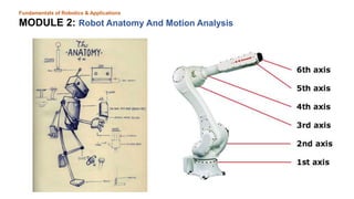
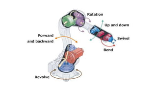
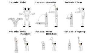
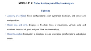
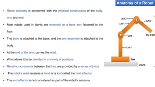
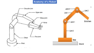
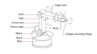
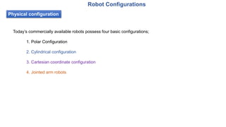
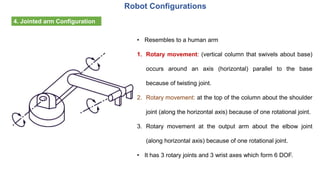
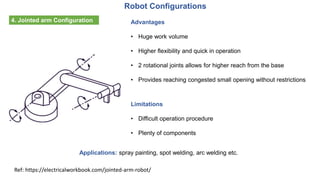
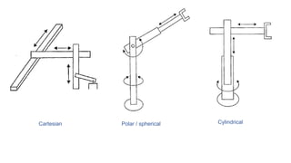
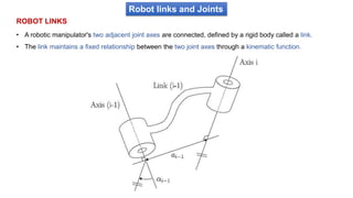

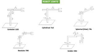
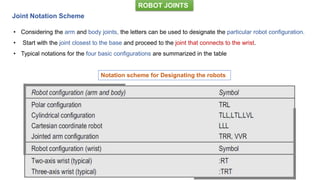
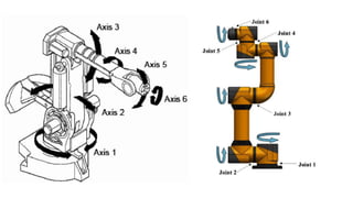
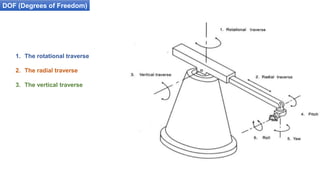
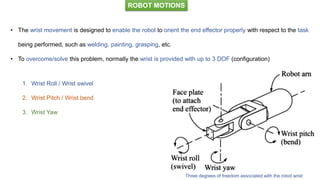
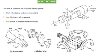
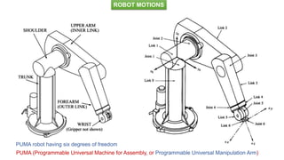


The document outlines a course on robotics fundamentals at JSS Academy, detailing course objectives, learning materials, and assessment methods. It covers robotic anatomy, configurations such as polar, cylindrical, Cartesian, and jointed arm, as well as kinematics involving forward and inverse calculations. Additionally, it explains degrees of freedom and the roles of various joints in robotic motion.