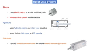
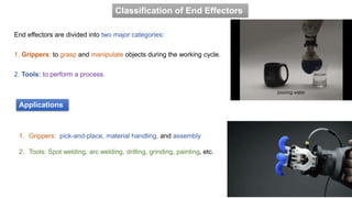
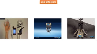
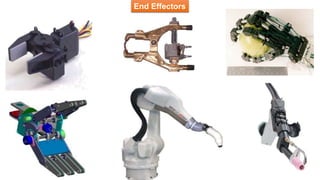
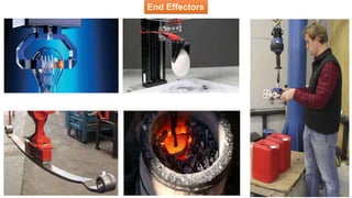
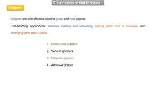
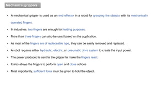
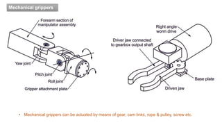
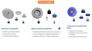
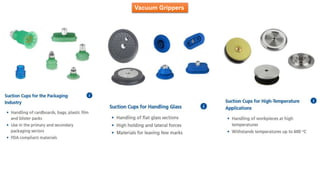
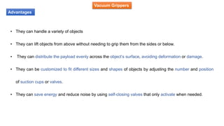
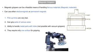
Fundamentals of Robotics and Applications
Department of Robotics & Automation
JSS Academy of Technical Education, Bangalore-560060
(Course Code: BRA301)
Books
• S.R. Deb, Robotics Technology and flexible automation, Tata McGraw-Hill Education, 2009.
• Mikell P. Groover et al., "Industrial Robots - Technology, Programming and Applications", McGraw
Hill, Special Edition, (2012).
• Ganesh S Hegde, “A textbook on Industrial Robotics”, University Science Press, 3rd edition,
2017.
Reference
• Richard D Klafter, Thomas A Chmielewski, Michael Negin, "Robotics Engineering – An Integrated
Approach", Eastern Economy Edition, Prentice Hall of India Pvt. Ltd., 2006.
• Fu K S, Gonzalez R C, Lee C.S.G, "Robotics: Control, Sensing, Vision and Intelligence", McGraw
Hill, 1987.
Further Learning
https://www.robots.com/applications
Continuous Internal Evaluation (CIE)
• Assignment Component = 25 Marks
• Internal Assessment (IA) component = 25 Marks
• Two IA Tests, each of 25 Marks
• Two assignments each of 25 Marks
• For the course, CIE marks will be based on a scaled-down sum of two tests and other
assessment methods.
The minimum passing mark for the CIE is 40% of the maximum marks (20 marks out of 50)
Semester End Examination(SEE)
• The question paper shall be set for 100 marks.
• The duration of SEE is 03 hours.
• The question paper will have 10 questions.
• 2 questions per module. Each question is set for 20 marks.
• The students have to answer 5 full questions, selecting one full question from each module.
• The student has to answer for 100 marks and marks scored out of 100 shall be
proportionally reduced to 50 marks.
• SEE minimum passing mark is 35% of the maximum marks (18 out of 50 marks).
• Students should secure a minimum of 40% (40 marks out of 100) in the sum total of the CIE and SEE
taken together.
Fundamentals of Robotics & Applications
MODULE 3: Robot Drives And End Effectors
Course outcomes (COs) (Course Skill Set)
CO4: Use the suitable drives and end-effectors for a given robotics application.
At the end of the course, students will be able to,
MODULE 3: Robot Drives And End Effectors
• Robot drive systems: Hydraulic, Pneumatic and Electric drive systems.
• Classification of end effectors: mechanical grippers, vacuum grippers, magnetic grippers,
and adhesive grippers.
• Gripper force analysis and gripper design.
• 1 DoF, 2 DoF, multiple degrees of freedom robot hand, tools as end effectors
• Robot control types: limited sequence control, point-to-point control, playback with continuous
path control, and intelligent control.
Content
Robot Drive Systems
Robot Drive Systems
• Drives and actuators form a drive system.
• Drives and transmission systems control various degrees of speed and torque to generate motion in a robot
• This control affects the precision, accuracy, and efficiency of industrial robots
1. Hydraulic actuators
2. Pneumatic actuators
3. Electrical actuators: Servomotors, Stepper motors or Direct-drive electric motors
• Robots require drive systems for moving their arms, wrist and body
• The joints are moved by actuators powered by a drive system
• The drive system, also used to determine the capacity of a robot
• The main types of actuators are;
Robot Drive Systems
Electric
• Uses electric motors to actuate individual joints
• Preferred drive system in today's robots
Hydraulic
• Uses hydraulic pistons and rotary vane actuators
• Noted for their high power and lift capacity
Pneumatic
• Typically limited to smaller robots and simple material transfer applications
Robot Drive Systems
• Hydraulic and pneumatic actuators generally drive prismatic joints since they produce linear motion
directly. Hence, Hydraulic and pneumatic actuators are also known as linear actuators.
• Electric motors are suited to driving revolute joints as they produce rotation (rotary actuators).
Robot Drive Systems
Hydraulic Systems
Robot Drive Systems
• Hydraulic drive systems are specifically designed for larger robots.
• They deliver high power and speed, greater than an electric drive system.
• This system can be used for both rotational and linear joints.
• Principle: an electric motor drives a pump that moves fluid from a reservoir. This causes oil to pass through
the control valves and enter the actuators.
• These systems deal with heavy machinery and operate smoothly, making effortless movements.
For example, palletization involves lifting and placing large products on a pallet for a shipment.
Hydraulic Systems
Robot Drive Systems
• In the hydraulic system, pressurized oil is provided by a pump
driven by an electric motor.
• The pump pumps oil from a sump through a non-return valve
and an accumulator to the system, from which it returns to the
sump.
• A pressure-relief valve is included to release the pressure if it
rises above a safe level.
• The non-return valve prevents the oil from being back driven
to the pump.
• The accumulator is to smooth out any short-term fluctuations
in the output oil pressure.
Hydraulic Systems
Robot Drive Systems
Examples of Hydraulic systems
Features of Hydraulic systems
• Provide high power in small light components
• Has flat load-speed or torque-speed characteristics
• Can operate safely and continuously under stall conditions
• Has a longer life and reliability due to the lubricating properties of the oil.
• Can be easily built using readily available standard elements.
• Have contaminant-sensitive elements.
• The operation is noisy.
• Higher inertia on the robot joints.
• Power loss and unclean work area due to the possibility of a leak.
• Less deflection due to low compliance of the elements.
Applications of Hydraulic systems
• Used to drive the spray coating robots.
• Used in heavy part-loading robots.
• Useful in material handling robot systems.
• Used to drive the joints of assembly (heavy) robots
• Useful in producing translatory motion in cartesian robots.
• Useful in robots operating in hazardous, sparking environments.
• Useful in gripper mechanisms.
Examples of actuators
Pneumatic Systems
Robot Drive Systems
• Pneumatic drive systems use compressed air, or pressurized gasses, to facilitate the movement of a robot.
• Air is compressed and then stored in a reservoir; from there, air is distributed through to the actuators.
• These systems are simple to construct and less expensive than hydraulic systems.
• The compressed air can also help absorb shock.
• The pressure of air used in this varies from 6-10 MPa
Pneumatic Systems
Robot Drive Systems
• In a pneumatic power supply, an electric motor drives an
air compressor.
• The air inlet to the compressor is filtered and via a silencer
to reduce the noise level.
• A pressure-relief valve provides protection against the
pressure in the system rising above a safe level.
• Since the temp. increases there is a cooling system.
• To remove contamination and water from the air, a filter
with a water trap is provided.
• An air receiver increases the air volume in the system and
smoothes out any short-term pressure fluctuations.
Examples of Pneumatic systems
Pneumatic Systems
Robot Drive Systems
• Lowest power to weight ratio.
• Highly compliant system.
• Drift under load constantly.
• Low, inaccurate response due to low stiffness.
• Less leakage of air and not susceptible to sparks.
• It uses low-pressure compressed air, hence, less actuation force or torque.
• Useful in on-off applications like pick and place robots.
• Simple and low-cost components.
• The exact positions of the actuators can be controlled by servo control valves by differential movements.
Robot Drive Systems
Electric Actuator
• Electric actuators convert electrical energy into mechanical motion.
• Commonly used actuators in robotics due to their high speed, precision, & ease of control.
• The working principle of an electric actuator is based on the electric motor.
• The motor generates rotary motion, converted into linear motion or other forms through mechanical
components such as gears, belts, or screws.
• Electric motors serve as the foundation for both linear actuators and rotary actuators
A motor works on the principle that when a rectangular coil is placed in a magnetic field and current is
passed through it. A force acts on the coil which rotates it continuously.
Robot Drive Systems
Electric Actuator
When a current-carrying conductor is placed in a magnetic field, it experiences a
mechanical force whose direction is given by Fleming's Left-hand rule.
Robot Drive Systems
• Precision & High Speed.
• They can be controlled accurately, allowing for precise movements and positioning.
• Ideal for tasks that require a high degree of accuracy, such as positioning a robotic arm or controlling
a surgical robot.
• They can move quickly and smoothly, suitable for tasks that require fast movements.
• E.g. In an assembly line, used to move parts into position (quickly and accurately).
• Highly adaptable and versatile, capable of performing a wide range of tasks.
Advantages
Electric Actuator
Robot Drive Systems
• Require a power source, such as a battery or a connection to the electrical grid.
• They can also generate heat during operation, which can be challenging in certain applications.
Limitations
Electric Actuator
Robot Drive Systems
Electric Actuator
Robot Drive Systems
Electric Actuator
Servo Motor
• Servomotors are special electromechanical devices that produce precise degrees of rotation.
• A servo motor is a DC or AC or brushless DC motor combined with a position sensing device.
• Servomotors are also called control motors, involved in controlling a mechanical system.
• The servomotors are used in a closed-loop servo system as shown in Fig.
Robot Drive Systems
Electric Actuator
Servo Motor
• A reference i/p is sent to the servo amplifier, which controls the speed of the servomotor.
• A feedback device is mounted on the machine, which is either an encoder or resolver. This device changes
mechanical motion into electrical signals and is used as a feedback.
• The feedback is sent to the error detector, which compares the actual operation with the reference input.
• Error is fed directly to the amplifier, used to make necessary corrections in control action.
• In servo systems, both velocity and position are monitored.
• Servomotors provide accurate speed, torque, and have ability of direction control.
Robot Drive Systems
Electric Actuator
Stepper Motor
• Stepper Motor is a brushless electromechanical device which converts the train of electric pulses applied at
their excitation windings into precisely defined steps of mechanical shaft rotation.
• The shaft of the motor rotates through a fixed angle for each discrete pulse.
• This rotation can be linear or angular. It gets one step movement for a single pulse input.
Robot Drive Systems
Electric Actuator
• At the beginning, coil A is energized and the rotor is aligned with the magnetic field it produces.
• When coil B is energized, the rotor rotates anticlockwise by 60° to align with the new magnetic field.
• The same happens when coil C is energized.
Stepper Motor
End Effectors
End Effectors
What is an end effector?
• They are tools attached to the end of a robotic arm that allows a robot to interact in an environment to
perform specific tasks.
• The end effector is purchased or designed separately from the robot
• A robotic arm can use different end effectors depending on the activity: holding, cutting, welding, painting and
moving different objects.
End effectors are divided into two major categories:
1. Grippers: to grasp and manipulate objects during the working cycle.
2. Tools: to perform a process.
Classification of End Effectors
1. Grippers: pick-and-place, material handling, and assembly
2. Tools: Spot welding, arc welding, drilling, grinding, painting, etc.
Applications
End Effectors
End Effectors
End Effectors
Grippers are end effectors used to grasp and hold objects.
Part-handling applications: machine loading and unloading, picking parts from a conveyor, and
arranging parts onto a pallet.
Classification of End Effectors
Grippers
1. Mechanical grippers
2. Vacuum grippers
3. Magnetic grippers
4. Adhesive gripper
Mechanical grippers
• A mechanical gripper is used as an end effector in a robot for grasping the objects with its mechanically
operated fingers.
• In industries, two fingers are enough for holding purposes.
• More than three fingers can also be used based on the application.
• As most of the fingers are of replaceable type, they can be easily removed and replaced.
• A robot requires either hydraulic, electric, or pneumatic drive system to create the input power.
• The power produced is sent to the gripper to make the fingers react.
• It also allows the fingers to perform open and close actions.
• Most importantly, sufficient force must be given to hold the object.
Mechanical grippers
• Mechanical grippers can be actuated by means of gear, cam links, rope & pulley, screw etc.
Mechanical grippers
• Mechanical grippers can be actuated by means of gear, cam links, rope & pulley, screw etc.
• Determine the force required to hold the object without
dropping it / crushing it.
• For this reason gripper design requires much knowledge
as possible of the range of items the gripper will be
expected to handle.
• Mass, size, shape & strength of grippers must be taken
into account.
Main Types of Mechanical Grippers
Parallel 2 or more “fingers”
Angular
Main Types of Mechanical Grippers
Mechanical Grippers: Limitations
• Dynamic forces and moments when sizing a gripper.
• Gripper could drop part with loss in air pressure
• Angular grippers are less expensive, but the arcing motion of the jaws may require additional tooling
clearance and will grip at varying points as part width varies.
• A parallel gripper is a simpler tool to compensate for part size variance.
Mechanical Grippers: Specifications
• Grip force: ranges tiny forces 0.1 lbs to over 1600 lbs (dynamic forces, moments)
• Part sizes: typically .01 to 36 inches
• Number of jaws: typically 2 to 4 jaws or fingers
• Repeatability: typically +/- .001 to .005 inches
• Cycles to failure: up to 10 million cycles
• Supporting technologies: air valves, air compressors, sensors, I/O interfaces
Mechanical Grippers: Specifications
Opening width and the speed of
gripping depends on the linkage
configuration.
A rack actuated by a hydraulic
/pneumatic cylinder operates two
pivoted pinions.
Pinions oscillate to move the racks.
cam attached to a cylinder moves to
and fro.
Spring-loaded followers move on the
cam profile.
A threaded block engages with a screw
moving forward and backwards; the fingers
attached to levers connected to the threaded
block by a hinged joint open and close,
providing releasing and gripping action.
Vacuum Grippers
• Vacuum grippers are end effectors that use suction cups to lift and
manipulate objects.
• Using the difference between a vacuum and atmospheric pressure, vacuum
grippers lift, hold, and move objects.
• The vacuum is created by a miniature electromechanical pump or
compressed air-driven pump.
• They are widely used for robotic palletising, which is the process of stacking
and arranging products on pallets for transportation or storage
Vacuum Grippers
• Suction cups used in this type of robot gripper are composed of a soft material.
• Some means of removing the air between the cup and the part surface to create the vacuum is required.
• The vacuum pump and the venturi are common devices used for this purpose.
• The vacuum pump is a piston-operated or vane-driven device powered by an electric motor.
• It is capable of creating a relatively high vacuum.
• Venturi is a device that can be driven by ‘shop air pressure’.
• The overall reliability of the vacuum system is dependent on the source of air pressure.
Vacuum Grippers
Vacuum Grippers
Vacuum Grippers
Advantages
• They can handle a variety of objects
• They can lift objects from above without needing to grip them from the sides or below.
• They can distribute the payload evenly across the object’s surface, avoiding deformation or damage.
• They can be customized to fit different sizes and shapes of objects by adjusting the number and position
of suction cups or valves.
• They can save energy and reduce noise by using self-closing valves that only activate when needed.
Magnetic Grippers
• Magnetic grippers can be a feasible means of handling ferrous materials (Magnetic materials).
• Can use either electromagnets or permanent magnets
1. Pick up times are very fast.
2. Can grip parts of various sizes
3. Ability to handle metal parts with holes (not possible with vacuum grippers)
4. They require only one surface for gripping.
Magnetic Grippers
Disadvantages with magnetic grippers include;
• Residual magnetism in the workpiece, which may cause a problem in subsequent handling
• Side slippage and other errors that limit the precision of handling.
• Problem of picking thin sheet from a stack. The magnetic attraction tends to penetrate beyond the top
sheet in the stack, resulting in the possibility that more than a single sheet will be lifted by the magnet
Adhesive Grippers
• Adhesive substance performs the grasping action
• Used to handle fabrics and other lightweight materials.
• Potential limitations of an adhesive gripper is that the adhesive substance loses its tackiness on repeated
usage, its reliability as a gripping device is diminished with each successive operation cycle.
• To overcome this limitation, the adhesive material is loaded in the form of a continuous ribbon into a feeding
mechanism that is attached to the robot wrist.
• To release the grasp on an object, some other means, such as devices that lock the gripped object into place
must be used.
TOOLS AS END EFFECTORS
Examples of tools used as end effectors in robot applications include:
1. Spot-welding tools
2. Arc-welding torch
3. Spray-painting nozzle
4. Liquid cement applicators for assembly
5. Heating torches
6. Water jet cutting
7. Rotating spindles for operations such as;
8. Drilling, Routing, Wire brushing, grinding
Gripper Force Analysis and Gripper Design
• The gripper must have the ability to reach the surface of a work part.
• The change in work part size must be accounted for providing accurate positioning.
• During machining operations, there will be a change in the work part size. As a result, the gripper must be
designed to hold a work part even when the size is varied.
• The gripper must not create any sort of distort and scratch in the fragile work parts.
• The gripper must hold the larger area of a work part if it has various dimensions, which will certainly
increase stability and control in positioning.
• The gripper can be designed with resilient pads to provide more grasping contacts in the work part.
• The replaceable fingers can also be employed for holding different work part sizes by its interchangeability
facility
Gripper Selection & Design Requirements
Gripper Force Analysis
• A gripper mechanism consisting of fingers, linkages frame and a pneumatic cylinder is shown in Fig.
• Air pressure supplied to the cylinder aids in actuating the fingers to grab an object.
• Gripper force = Pg.
• m = mass of the object
• g = gravity acceleration.
• Force due to mass = m.g = W, newtons ------(i)
• The friction between the finger pads is responsible for the gripper to hold the object exerting the force W
Gripper Force Analysis
• The friction force is given by f = μ N Pg ………(ii)
μ = coefficient of friction
N = the number of fingers
• Depending on the circumstances the capacity of the fingers has to be increased, incorporate a safety
by a factor of safety, n.
• i.e., Fd = design force = n.W ……………(iii)
Gripper Force Analysis
Equating equations (ii) and (iii)
n.W = μ N Pg
If the gripper is accelerating or decelerating by 'a'
'a’ = positive sign when accelerating down and negative sign when accelerating up.
The expression can also be written as
Gripper Force Analysis
Gripper Selection & Design Requirements
End

Robot Drives And End Effectors.pptx

  • 1.
    Fundamentals of Roboticsand Applications Department of Robotics & Automation JSS Academy of Technical Education, Bangalore-560060 (Course Code: BRA301)
  • 2.
    Books • S.R. Deb,Robotics Technology and flexible automation, Tata McGraw-Hill Education, 2009. • Mikell P. Groover et al., "Industrial Robots - Technology, Programming and Applications", McGraw Hill, Special Edition, (2012). • Ganesh S Hegde, “A textbook on Industrial Robotics”, University Science Press, 3rd edition, 2017. Reference • Richard D Klafter, Thomas A Chmielewski, Michael Negin, "Robotics Engineering – An Integrated Approach", Eastern Economy Edition, Prentice Hall of India Pvt. Ltd., 2006. • Fu K S, Gonzalez R C, Lee C.S.G, "Robotics: Control, Sensing, Vision and Intelligence", McGraw Hill, 1987. Further Learning https://www.robots.com/applications
  • 3.
    Continuous Internal Evaluation(CIE) • Assignment Component = 25 Marks • Internal Assessment (IA) component = 25 Marks • Two IA Tests, each of 25 Marks • Two assignments each of 25 Marks • For the course, CIE marks will be based on a scaled-down sum of two tests and other assessment methods. The minimum passing mark for the CIE is 40% of the maximum marks (20 marks out of 50)
  • 4.
    Semester End Examination(SEE) •The question paper shall be set for 100 marks. • The duration of SEE is 03 hours. • The question paper will have 10 questions. • 2 questions per module. Each question is set for 20 marks. • The students have to answer 5 full questions, selecting one full question from each module. • The student has to answer for 100 marks and marks scored out of 100 shall be proportionally reduced to 50 marks. • SEE minimum passing mark is 35% of the maximum marks (18 out of 50 marks). • Students should secure a minimum of 40% (40 marks out of 100) in the sum total of the CIE and SEE taken together.
  • 5.
    Fundamentals of Robotics& Applications MODULE 3: Robot Drives And End Effectors
  • 6.
    Course outcomes (COs)(Course Skill Set) CO4: Use the suitable drives and end-effectors for a given robotics application. At the end of the course, students will be able to,
  • 7.
    MODULE 3: RobotDrives And End Effectors • Robot drive systems: Hydraulic, Pneumatic and Electric drive systems. • Classification of end effectors: mechanical grippers, vacuum grippers, magnetic grippers, and adhesive grippers. • Gripper force analysis and gripper design. • 1 DoF, 2 DoF, multiple degrees of freedom robot hand, tools as end effectors • Robot control types: limited sequence control, point-to-point control, playback with continuous path control, and intelligent control. Content
  • 8.
  • 9.
    Robot Drive Systems •Drives and actuators form a drive system. • Drives and transmission systems control various degrees of speed and torque to generate motion in a robot • This control affects the precision, accuracy, and efficiency of industrial robots 1. Hydraulic actuators 2. Pneumatic actuators 3. Electrical actuators: Servomotors, Stepper motors or Direct-drive electric motors • Robots require drive systems for moving their arms, wrist and body • The joints are moved by actuators powered by a drive system • The drive system, also used to determine the capacity of a robot • The main types of actuators are;
  • 10.
    Robot Drive Systems Electric •Uses electric motors to actuate individual joints • Preferred drive system in today's robots Hydraulic • Uses hydraulic pistons and rotary vane actuators • Noted for their high power and lift capacity Pneumatic • Typically limited to smaller robots and simple material transfer applications
  • 11.
    Robot Drive Systems •Hydraulic and pneumatic actuators generally drive prismatic joints since they produce linear motion directly. Hence, Hydraulic and pneumatic actuators are also known as linear actuators. • Electric motors are suited to driving revolute joints as they produce rotation (rotary actuators).
  • 12.
  • 13.
    Hydraulic Systems Robot DriveSystems • Hydraulic drive systems are specifically designed for larger robots. • They deliver high power and speed, greater than an electric drive system. • This system can be used for both rotational and linear joints. • Principle: an electric motor drives a pump that moves fluid from a reservoir. This causes oil to pass through the control valves and enter the actuators. • These systems deal with heavy machinery and operate smoothly, making effortless movements. For example, palletization involves lifting and placing large products on a pallet for a shipment.
  • 14.
    Hydraulic Systems Robot DriveSystems • In the hydraulic system, pressurized oil is provided by a pump driven by an electric motor. • The pump pumps oil from a sump through a non-return valve and an accumulator to the system, from which it returns to the sump. • A pressure-relief valve is included to release the pressure if it rises above a safe level. • The non-return valve prevents the oil from being back driven to the pump. • The accumulator is to smooth out any short-term fluctuations in the output oil pressure.
  • 15.
  • 16.
  • 17.
    Features of Hydraulicsystems • Provide high power in small light components • Has flat load-speed or torque-speed characteristics • Can operate safely and continuously under stall conditions • Has a longer life and reliability due to the lubricating properties of the oil. • Can be easily built using readily available standard elements. • Have contaminant-sensitive elements. • The operation is noisy. • Higher inertia on the robot joints. • Power loss and unclean work area due to the possibility of a leak. • Less deflection due to low compliance of the elements.
  • 18.
    Applications of Hydraulicsystems • Used to drive the spray coating robots. • Used in heavy part-loading robots. • Useful in material handling robot systems. • Used to drive the joints of assembly (heavy) robots • Useful in producing translatory motion in cartesian robots. • Useful in robots operating in hazardous, sparking environments. • Useful in gripper mechanisms.
  • 19.
  • 20.
    Pneumatic Systems Robot DriveSystems • Pneumatic drive systems use compressed air, or pressurized gasses, to facilitate the movement of a robot. • Air is compressed and then stored in a reservoir; from there, air is distributed through to the actuators. • These systems are simple to construct and less expensive than hydraulic systems. • The compressed air can also help absorb shock. • The pressure of air used in this varies from 6-10 MPa
  • 21.
    Pneumatic Systems Robot DriveSystems • In a pneumatic power supply, an electric motor drives an air compressor. • The air inlet to the compressor is filtered and via a silencer to reduce the noise level. • A pressure-relief valve provides protection against the pressure in the system rising above a safe level. • Since the temp. increases there is a cooling system. • To remove contamination and water from the air, a filter with a water trap is provided. • An air receiver increases the air volume in the system and smoothes out any short-term pressure fluctuations.
  • 22.
  • 23.
    Pneumatic Systems Robot DriveSystems • Lowest power to weight ratio. • Highly compliant system. • Drift under load constantly. • Low, inaccurate response due to low stiffness. • Less leakage of air and not susceptible to sparks. • It uses low-pressure compressed air, hence, less actuation force or torque. • Useful in on-off applications like pick and place robots. • Simple and low-cost components. • The exact positions of the actuators can be controlled by servo control valves by differential movements.
  • 24.
    Robot Drive Systems ElectricActuator • Electric actuators convert electrical energy into mechanical motion. • Commonly used actuators in robotics due to their high speed, precision, & ease of control. • The working principle of an electric actuator is based on the electric motor. • The motor generates rotary motion, converted into linear motion or other forms through mechanical components such as gears, belts, or screws. • Electric motors serve as the foundation for both linear actuators and rotary actuators A motor works on the principle that when a rectangular coil is placed in a magnetic field and current is passed through it. A force acts on the coil which rotates it continuously.
  • 25.
    Robot Drive Systems ElectricActuator When a current-carrying conductor is placed in a magnetic field, it experiences a mechanical force whose direction is given by Fleming's Left-hand rule.
  • 26.
    Robot Drive Systems •Precision & High Speed. • They can be controlled accurately, allowing for precise movements and positioning. • Ideal for tasks that require a high degree of accuracy, such as positioning a robotic arm or controlling a surgical robot. • They can move quickly and smoothly, suitable for tasks that require fast movements. • E.g. In an assembly line, used to move parts into position (quickly and accurately). • Highly adaptable and versatile, capable of performing a wide range of tasks. Advantages Electric Actuator
  • 27.
    Robot Drive Systems •Require a power source, such as a battery or a connection to the electrical grid. • They can also generate heat during operation, which can be challenging in certain applications. Limitations Electric Actuator
  • 28.
  • 29.
    Robot Drive Systems ElectricActuator Servo Motor • Servomotors are special electromechanical devices that produce precise degrees of rotation. • A servo motor is a DC or AC or brushless DC motor combined with a position sensing device. • Servomotors are also called control motors, involved in controlling a mechanical system. • The servomotors are used in a closed-loop servo system as shown in Fig.
  • 30.
    Robot Drive Systems ElectricActuator Servo Motor • A reference i/p is sent to the servo amplifier, which controls the speed of the servomotor. • A feedback device is mounted on the machine, which is either an encoder or resolver. This device changes mechanical motion into electrical signals and is used as a feedback. • The feedback is sent to the error detector, which compares the actual operation with the reference input. • Error is fed directly to the amplifier, used to make necessary corrections in control action. • In servo systems, both velocity and position are monitored. • Servomotors provide accurate speed, torque, and have ability of direction control.
  • 31.
    Robot Drive Systems ElectricActuator Stepper Motor • Stepper Motor is a brushless electromechanical device which converts the train of electric pulses applied at their excitation windings into precisely defined steps of mechanical shaft rotation. • The shaft of the motor rotates through a fixed angle for each discrete pulse. • This rotation can be linear or angular. It gets one step movement for a single pulse input.
  • 32.
    Robot Drive Systems ElectricActuator • At the beginning, coil A is energized and the rotor is aligned with the magnetic field it produces. • When coil B is energized, the rotor rotates anticlockwise by 60° to align with the new magnetic field. • The same happens when coil C is energized. Stepper Motor
  • 33.
  • 34.
    End Effectors What isan end effector? • They are tools attached to the end of a robotic arm that allows a robot to interact in an environment to perform specific tasks. • The end effector is purchased or designed separately from the robot • A robotic arm can use different end effectors depending on the activity: holding, cutting, welding, painting and moving different objects.
  • 35.
    End effectors aredivided into two major categories: 1. Grippers: to grasp and manipulate objects during the working cycle. 2. Tools: to perform a process. Classification of End Effectors 1. Grippers: pick-and-place, material handling, and assembly 2. Tools: Spot welding, arc welding, drilling, grinding, painting, etc. Applications
  • 36.
  • 37.
  • 38.
  • 40.
    Grippers are endeffectors used to grasp and hold objects. Part-handling applications: machine loading and unloading, picking parts from a conveyor, and arranging parts onto a pallet. Classification of End Effectors Grippers 1. Mechanical grippers 2. Vacuum grippers 3. Magnetic grippers 4. Adhesive gripper
  • 41.
    Mechanical grippers • Amechanical gripper is used as an end effector in a robot for grasping the objects with its mechanically operated fingers. • In industries, two fingers are enough for holding purposes. • More than three fingers can also be used based on the application. • As most of the fingers are of replaceable type, they can be easily removed and replaced. • A robot requires either hydraulic, electric, or pneumatic drive system to create the input power. • The power produced is sent to the gripper to make the fingers react. • It also allows the fingers to perform open and close actions. • Most importantly, sufficient force must be given to hold the object.
  • 42.
    Mechanical grippers • Mechanicalgrippers can be actuated by means of gear, cam links, rope & pulley, screw etc.
  • 43.
    Mechanical grippers • Mechanicalgrippers can be actuated by means of gear, cam links, rope & pulley, screw etc. • Determine the force required to hold the object without dropping it / crushing it. • For this reason gripper design requires much knowledge as possible of the range of items the gripper will be expected to handle. • Mass, size, shape & strength of grippers must be taken into account.
  • 44.
    Main Types ofMechanical Grippers Parallel 2 or more “fingers” Angular
  • 45.
    Main Types ofMechanical Grippers
  • 46.
    Mechanical Grippers: Limitations •Dynamic forces and moments when sizing a gripper. • Gripper could drop part with loss in air pressure • Angular grippers are less expensive, but the arcing motion of the jaws may require additional tooling clearance and will grip at varying points as part width varies. • A parallel gripper is a simpler tool to compensate for part size variance.
  • 47.
    Mechanical Grippers: Specifications •Grip force: ranges tiny forces 0.1 lbs to over 1600 lbs (dynamic forces, moments) • Part sizes: typically .01 to 36 inches • Number of jaws: typically 2 to 4 jaws or fingers • Repeatability: typically +/- .001 to .005 inches • Cycles to failure: up to 10 million cycles • Supporting technologies: air valves, air compressors, sensors, I/O interfaces
  • 48.
    Mechanical Grippers: Specifications Openingwidth and the speed of gripping depends on the linkage configuration. A rack actuated by a hydraulic /pneumatic cylinder operates two pivoted pinions. Pinions oscillate to move the racks. cam attached to a cylinder moves to and fro. Spring-loaded followers move on the cam profile. A threaded block engages with a screw moving forward and backwards; the fingers attached to levers connected to the threaded block by a hinged joint open and close, providing releasing and gripping action.
  • 49.
    Vacuum Grippers • Vacuumgrippers are end effectors that use suction cups to lift and manipulate objects. • Using the difference between a vacuum and atmospheric pressure, vacuum grippers lift, hold, and move objects. • The vacuum is created by a miniature electromechanical pump or compressed air-driven pump. • They are widely used for robotic palletising, which is the process of stacking and arranging products on pallets for transportation or storage
  • 50.
    Vacuum Grippers • Suctioncups used in this type of robot gripper are composed of a soft material. • Some means of removing the air between the cup and the part surface to create the vacuum is required. • The vacuum pump and the venturi are common devices used for this purpose. • The vacuum pump is a piston-operated or vane-driven device powered by an electric motor. • It is capable of creating a relatively high vacuum. • Venturi is a device that can be driven by ‘shop air pressure’. • The overall reliability of the vacuum system is dependent on the source of air pressure.
  • 51.
  • 52.
  • 53.
    Vacuum Grippers Advantages • Theycan handle a variety of objects • They can lift objects from above without needing to grip them from the sides or below. • They can distribute the payload evenly across the object’s surface, avoiding deformation or damage. • They can be customized to fit different sizes and shapes of objects by adjusting the number and position of suction cups or valves. • They can save energy and reduce noise by using self-closing valves that only activate when needed.
  • 54.
    Magnetic Grippers • Magneticgrippers can be a feasible means of handling ferrous materials (Magnetic materials). • Can use either electromagnets or permanent magnets 1. Pick up times are very fast. 2. Can grip parts of various sizes 3. Ability to handle metal parts with holes (not possible with vacuum grippers) 4. They require only one surface for gripping.
  • 55.
    Magnetic Grippers Disadvantages withmagnetic grippers include; • Residual magnetism in the workpiece, which may cause a problem in subsequent handling • Side slippage and other errors that limit the precision of handling. • Problem of picking thin sheet from a stack. The magnetic attraction tends to penetrate beyond the top sheet in the stack, resulting in the possibility that more than a single sheet will be lifted by the magnet
  • 56.
    Adhesive Grippers • Adhesivesubstance performs the grasping action • Used to handle fabrics and other lightweight materials. • Potential limitations of an adhesive gripper is that the adhesive substance loses its tackiness on repeated usage, its reliability as a gripping device is diminished with each successive operation cycle. • To overcome this limitation, the adhesive material is loaded in the form of a continuous ribbon into a feeding mechanism that is attached to the robot wrist. • To release the grasp on an object, some other means, such as devices that lock the gripped object into place must be used.
  • 57.
    TOOLS AS ENDEFFECTORS Examples of tools used as end effectors in robot applications include: 1. Spot-welding tools 2. Arc-welding torch 3. Spray-painting nozzle 4. Liquid cement applicators for assembly 5. Heating torches 6. Water jet cutting 7. Rotating spindles for operations such as; 8. Drilling, Routing, Wire brushing, grinding
  • 58.
    Gripper Force Analysisand Gripper Design
  • 59.
    • The grippermust have the ability to reach the surface of a work part. • The change in work part size must be accounted for providing accurate positioning. • During machining operations, there will be a change in the work part size. As a result, the gripper must be designed to hold a work part even when the size is varied. • The gripper must not create any sort of distort and scratch in the fragile work parts. • The gripper must hold the larger area of a work part if it has various dimensions, which will certainly increase stability and control in positioning. • The gripper can be designed with resilient pads to provide more grasping contacts in the work part. • The replaceable fingers can also be employed for holding different work part sizes by its interchangeability facility Gripper Selection & Design Requirements
  • 60.
    Gripper Force Analysis •A gripper mechanism consisting of fingers, linkages frame and a pneumatic cylinder is shown in Fig. • Air pressure supplied to the cylinder aids in actuating the fingers to grab an object. • Gripper force = Pg. • m = mass of the object • g = gravity acceleration. • Force due to mass = m.g = W, newtons ------(i) • The friction between the finger pads is responsible for the gripper to hold the object exerting the force W
  • 61.
    Gripper Force Analysis •The friction force is given by f = μ N Pg ………(ii) μ = coefficient of friction N = the number of fingers • Depending on the circumstances the capacity of the fingers has to be increased, incorporate a safety by a factor of safety, n. • i.e., Fd = design force = n.W ……………(iii)
  • 62.
    Gripper Force Analysis Equatingequations (ii) and (iii) n.W = μ N Pg If the gripper is accelerating or decelerating by 'a' 'a’ = positive sign when accelerating down and negative sign when accelerating up.
  • 63.
    The expression canalso be written as Gripper Force Analysis
  • 64.
    Gripper Selection &Design Requirements
  • 65.