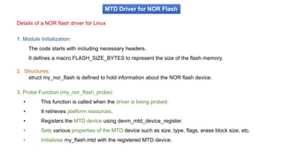
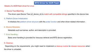
Downloaded 26 times


![3. Registering mtd_info
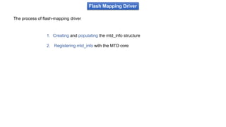
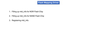
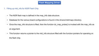
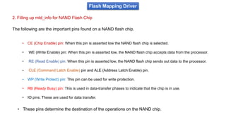
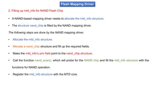
Flash Mapping Driver
• The basis of the registration is the function add_mtd_device() function, which adds the device to the
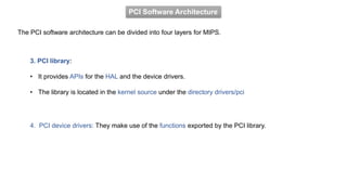
mtd_table[] array.
• In most cases, you would not use this function directly because you want to create partitions on the chip.](https://image.slidesharecdn.com/module3bsp-240213174319-7c3fc6cb/85/BSP-pptx-67-320.jpg)


The document outlines the Board Support Packages (BSP) module for embedded systems, detailing the essential software components needed for hardware integration with operating systems, particularly within the context of Linux. It covers topics such as bootloader functionality, memory mapping, interrupt management, and the Peripheral Component Interconnect (PCI) subsystem, highlighting performance optimization and resource utilization. Additionally, the document specifies course outcomes and evaluation criteria for students in a robotics and automation program at JSS Academy of Technical Education, Bangalore.