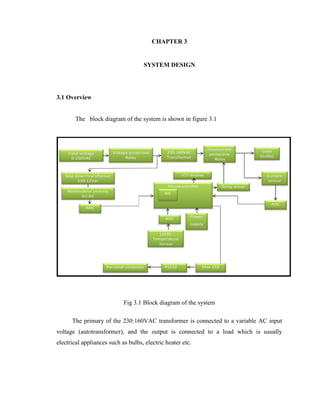
This document provides an introduction and background to a project on designing a microcontroller-based transformer protection system. It discusses how transformers are critical components in power systems that require protection against faults like short circuits, overcurrent and overvoltage. The document then reviews previous work on transformer protection and outlines the objectives of this project, which are to design current and voltage sensing circuits, develop a microcontroller algorithm for overload, overvoltage and undervoltage protection, and test the system's performance. The chapter concludes by outlining the scope and limitations of the project, which involves both hardware and software design to develop a protection system that can monitor transformer parameters and trip circuit breakers or relays during faults.
Differential protection of power transformerSaad Muftah
This thesis analyzes traditional and improved transformer differential protective relays. It proposes a technique using DC harmonic restraining combined with 2nd harmonic blocking to prevent relay tripping during transformer energization while maintaining security during faults. Simulation results show the method can distinguish between inrush and fault currents, with no unnecessary delays for faults. Testing of various parameter settings found blocking for 15-25% 2nd harmonic content over 3-20 cycles minimized misoperations without reducing security. The improved differential relay performance was validated through simulations and laboratory tests.
A power quality monitoring system gathers and analyzes electricity measurement data to provide useful information. It allows plants to perform energy management, preventive maintenance, quality control, and save money. Power quality monitoring equipment includes digital fault recorders, smart relays, voltage recorders, in-plant power monitors, and special-purpose power quality equipment. These devices monitor voltage, current, and other measurements to detect issues like harmonics, sags, disturbances and optimize power quality and performance.
Power Transformer Differential protectionRishi Tandon
This document discusses power transformer protection. It begins by explaining that transformers are static devices that transform electrical energy between circuits without changing frequency. Power transformers are vital but expensive components that are difficult to repair if damaged. Transformer protection is needed to prevent severe damage from faults and ensure continuous network operation. Common fault types and causes are then outlined, including insulation breakdown, overheating, contamination, and phase/turn faults. The document proceeds to describe the general scheme of differential protection and specific protection functions like bias differential, overfluxing, over/under voltage, and restricted earth fault protection. It provides an example calculation for setting a transformer differential relay and diagrams demonstrating differential relay operation. Finally, it reviews models from various manufacturers and presents a case study
FUNDAMENTALS OF POWER SYSTEM PROTECTION
FUNDAMENTALS OF POWER SYSTEM PROTECTIONFUNDAMENTALS OF POWER SYSTEM PROTECTIONFUNDAMENTALS OF POWER SYSTEM PROTECTIONFUNDAMENTALS OF POWER SYSTEM PROTECTIONFUNDAMENTALS OF POWER SYSTEM PROTECTIONFUNDAMENTALS OF POWER SYSTEM PROTECTIONFUNDAMENTALS OF POWER SYSTEM PROTECTIONFUNDAMENTALS OF POWER SYSTEM PROTECTIONFUNDAMENTALS OF POWER SYSTEM PROTECTIONFUNDAMENTALS OF POWER SYSTEM PROTECTIONFUNDAMENTALS OF POWER SYSTEM PROTECTIONFUNDAMENTALS OF POWER SYSTEM PROTECTIONFUNDAMENTALS OF POWER SYSTEM PROTECTIONFUNDAMENTALS OF POWER SYSTEM PROTECTIONFUNDAMENTALS OF POWER SYSTEM PROTECTIONFUNDAMENTALS OF POWER SYSTEM PROTECTIONFUNDAMENTALS OF POWER SYSTEM PROTECTIONFUNDAMENTALS OF POWER SYSTEM PROTECTIONFUNDAMENTALS OF POWER SYSTEM PROTECTIONFUNDAMENTALS OF POWER SYSTEM PROTECTIONFUNDAMENTALS OF POWER SYSTEM PROTECTIONFUNDAMENTALS OF POWER SYSTEM PROTECTIONFUNDAMENTALS OF POWER SYSTEM PROTECTIONFUNDAMENTALS OF POWER SYSTEM PROTECTIONFUNDAMENTALS OF POWER SYSTEM PROTECTIONFUNDAMENTALS OF POWER SYSTEM PROTECTIONFUNDAMENTALS OF POWER SYSTEM PROTECTIONFUNDAMENTALS OF POWER SYSTEM PROTECTIONFUNDAMENTALS OF POWER SYSTEM PROTECTIONFUNDAMENTALS OF POWER SYSTEM PROTECTIONFUNDAMENTALS OF POWER SYSTEM PROTECTIONFUNDAMENTALS OF POWER SYSTEM PROTECTIONFUNDAMENTALS OF POWER SYSTEM PROTECTIONFUNDAMENTALS OF POWER SYSTEM PROTECTIONFUNDAMENTALS OF POWER SYSTEM PROTECTIONFUNDAMENTALS OF POWER SYSTEM PROTECTIONFUNDAMENTALS OF POWER SYSTEM PROTECTIONFUNDAMENTALS OF POWER SYSTEM PROTECTIONFUNDAMENTALS OF POWER SYSTEM PROTECTIONFUNDAMENTALS OF POWER SYSTEM PROTECTIONFUNDAMENTALS OF POWER SYSTEM PROTECTIONFUNDAMENTALS OF POWER SYSTEM PROTECTIONFUNDAMENTALS OF POWER SYSTEM PROTECTIONFUNDAMENTALS OF POWER SYSTEM PROTECTIONFUNDAMENTALS OF POWER SYSTEM PROTECTIONFUNDAMENTALS OF POWER SYSTEM PROTECTIONFUNDAMENTALS OF POWER SYSTEM PROTECTION
Busbar protection uses differential protection to isolate faults on the busbar. It works by comparing the current entering and leaving the busbar using CTs - any difference indicates an internal fault. Proper CT ratios and a stabilizing resistance are needed to restrain operation for external faults. PS class CTs are preferred over other classes due to more consistent accuracy. While busbar protection is important, it is currently not implemented in line at MRSS due to some unspecified reason.
this is useful for peoples interested in power quality problems and their mitigation. it provides causes, effects of voltage sag and their mitigation techniques.
These slides presents the different challenges and issues related to DG integration to Micro-grid distribution systems. The possible solutions are also presented. Later of the class I will try to upload the mathematical presentations and simulation results related to each protection scheme. However, your suggestions are always welcome.
Loading Capability Limits of Transmission LinesRaja Adapa
This document discusses the four main loading capability limits of transmission lines: thermal, voltage, dielectric, and stability limits. The thermal limit depends on ambient temperature, wind conditions, conductor size and is usually the main limiting factor. Voltage limits require the transmission voltage to be maintained within a specified range, like plus/minus 5% of nominal. The dielectric limit concerns insulation and allows for some increase in normal operating voltage. Stability limits involve ensuring the power system remains stable after the loss of a single element to prevent cascading outages. FACTS technology can help utilize more of the thermal limits and improve stability.
Simplified analysis of graetz circuit copy - copyVert Wheeler
The document summarizes the analysis of a Graetz circuit, which is used in HVDC transmission, under two scenarios: without overlap and with overlap between thyristor valves. In the without overlap scenario, the analysis assumes valves switch on and off instantaneously with no two valves on at once. This allows simplifying the circuit to determine voltage and current waveforms. When overlap is considered and two valves can be on simultaneously, the analysis is more complex with different operation modes identified depending on the overlap angle. Key aspects of voltage, current, power factor and harmonics are derived.
The document discusses short circuit analysis and fault calculations. It describes the different types of faults including three phase, line to ground, and line to line faults. It also discusses the need for short circuit studies to select proper circuit breakers. The document explains how to calculate short circuit currents using the bus impedance matrix and the z-bus building algorithm through adding network elements one by one.
Power system-protection-presentation-dated-03-10-2013-integrated-protection-c...jbpatel7290
The document discusses numerical relays and their advantages over electromagnetic relays. It describes the functions and features of microprocessor-based numerical relays used for protection of transmission lines, transformers, busbars, distribution feeders, generators and motors. Numerical relays offer benefits like low cost, mathematical processing capabilities, self-checking, low burden on CTs/PTs, metering, fault recording, fault location, event logging and oscillography. Digital relays also provide standard hardware, flexibility in operation, multi-functionality, communication capabilities, adaptive relaying, and connectivity with SCADA systems. Block diagrams of generic digital relays and their hardware components are also presented.
Transmission lines require protective schemes due to their long lengths and exposure to the open atmosphere, making faults more common. The key methods for protecting transmission lines are:
1. Unit and non-unit type protections, with the main types being differential, overcurrent, distance, and carrier current protections.
2. Distance relays operate based on the impedance seen from the relay location, tripping if the impedance indicates a fault within the reach of the relay. Directional distance relays can discriminate between faults in different directions.
3. A three-step distance protection scheme uses underreach, definite reach, and overreach zones to isolate faults along the transmission line while coordinating protection across multiple line sections
This document discusses power quality monitoring. It defines power quality as the properties of the power supply delivered to users. Power quality can be affected by various steady state variations and events that cause deviations from the ideal voltage waveform. The document describes different types of power quality disturbances and how automatic classifiers are used to classify disturbances. It discusses power quality monitoring objectives and the types of commercially available power quality monitors used to identify and analyze power quality problems.
This document discusses active and reactive power flow control using a Static Synchronous Series Compensator (SSSC). The SSSC injects a controllable voltage in series with a transmission line to regulate power flow. It can control both real and reactive power flow to improve transmission efficiency. The SSSC consists of a voltage source converter connected to the line via a transformer. It provides advantages like power factor correction, load balancing, and reducing harmonic distortion.
In microgrid, if fault occurs or any other contingency happens, then the problems would be created which are related to power flow, also there are various protection schemes are used for minimize or eliminate these problems.
Voltage control is used for reactive power balance and P-f control is used for active power control.
Various protection schemes such as, over current protection, differential protection scheme, zoning of network in adaptive protection scheme are used in microgrid system .
The document discusses relay coordination and grading methods for protective relays in power systems. It describes various coordination techniques including current grading, time grading, and a combination of time and current grading using inverse definite minimum time (IDMT) characteristics. The key aspects covered are:
1) Current grading sets relays closer to the power source to operate at higher fault currents. Time grading sets relays to operate at progressively longer times closer to the source.
2) IDMT coordination uses inverse-time overcurrent relays set to different time multiples and pickup currents to achieve coordination over a wide range of fault levels.
3) Proper coordination requires isolating the faulty section, preventing tripping of healthy equipment, and
This document provides an overview of fundamentals of distance protection for transmission lines. It discusses types of transmission lines and typical protection schemes used based on line length. It then describes what distance protection is and challenges in relay design related to transients. The document outlines considerations for distance relay characteristics, polarization, and schemes including non-pilot and pilot schemes. It discusses redundancy, security, out-of-step relaying and series compensation.
The document discusses busbar protection, including the need for busbar protection, types of busbar protections like high impedance, medium impedance and low impedance protections. It describes the requirements of busbar protection like short tripping time and stable operation during external faults. The document discusses different busbar arrangements and applications of numerical busbar protection systems like RADSS. It provides examples of busbar protection schemes for different bus configurations. The document also includes excerpts from technical manuals providing recommendations on busbar protection in substations.
This document discusses power system protection settings and provides information on calculating protection settings. It covers the functions of protective relays and equipment protection, the required information for setting calculations such as line parameters and fault studies, and the process of calculating, checking, and implementing protection settings. The goal is to set protections to operate dependably, securely, and selectively during faults while meeting clearance time requirements.
This document is a final year project presentation on Static VAR Compensator (SVC). It discusses Flexible AC Transmission Systems (FACTS) which use power electronics to control power flow and increase transmission capacity. SVCs in particular provide fast reactive power support to control voltage and improve stability. Different types of SVC are described including series and shunt compensators using thyristor controlled capacitors and reactors. Mechanically Switched Capacitors are also discussed as a type of shunt compensator. The project layout and applications of SVC systems for transmission systems are outlined.
This document discusses the various types of testing required for protection equipment, including:
- Type tests to prove the relay meets specifications and standards under abnormal power conditions.
- Routine factory production tests to check for defects during manufacturing.
- Commissioning tests to prove correct installation of a protection scheme before use.
- Periodic maintenance tests to identify equipment failures or degradation over time.
Electrical type tests are described in detail, including functional, rating, thermal withstand, burden, input, output, and insulation resistance tests. The purpose is to thoroughly evaluate performance and safety.
This presentation provides an overview of power quality, including definitions of power quality, common power quality disturbances like sags, swells, harmonics and interruptions. It discusses the increased sensitivity of modern electronic equipment to power quality issues. Real-time power quality monitoring systems are described that can identify issues, locate their sources, and help utilities and customers mitigate problems to reduce costs and equipment damage. The benefits of power quality monitoring include improved reliability, preventative maintenance, and identification of sensitive equipment needing protection.
1. HVDC transmission systems use direct current for electricity transmission over long distances or through underwater cables. This became practical with the development of thyristors and solid state valves.
2. DC transmission has advantages over AC transmission for long distance transmission, as power transfer in DC lines is unaffected by distance. It also allows asynchronous interconnection between grids and monopolar operation.
3. While DC transmission has higher upfront equipment costs, it has better technical performance than AC transmission for long distance or underwater cables, making it economical beyond the break-even distance.
voltage stability by compensating reactive powerDurgarao Gundu
This document summarizes a student project report on stabilizing voltage by compensating reactive power. The objectives of the project are to explain how to improve voltage stability by installing sources of reactive power at distribution system buses. Reactive power compensation devices like shunt capacitors, SVCs, and TCRs can directly deliver reactive power to buses to maintain constant voltage despite varying load. The report will simulate and analyze the effects of these devices on voltage stabilization.
Transformer protection using microcontroller and gsm technologyKartik Patel
This document describes a project to protect transformers from overload conditions using a microcontroller and GSM technology. It includes a block diagram and explanation of the circuit diagram. The key components are a step-down transformer, rectifier, microcontroller, current transformer, voltage transformer, and relays. The microcontroller monitors the current and voltage, and can trigger the relays to disconnect the transformer if the load exceeds safe levels, while also sending a message via GSM to alert authorities. The objectives are to prevent transformer damage from overloading and allow for load sharing to increase lifespan.
MY PROJECT-automatic load sharing of transformer by using GSM tecnique.nikhilhiware
This document summarizes a student project on automatic load sharing of transformers using GSM technique. The objectives are to protect domestic and power transformers from overload by sharing the load between two parallel transformers when the load increases above a threshold. A PIC microcontroller monitors the current and voltage, and controls relays to disconnect one or both transformers if the load is too high. It can also send load information via text message using a GSM modem. The circuit includes transformers, rectifiers, regulators, relays, current and voltage measurement circuits connected to the PIC microcontroller. This helps prevent overheating, increases transformer life, and acts as an uninterruptible power supply.
GSM Based Fault Monitoring System (Project)Aishwary Verma
This is a modern technique of Monitoring of switchyard which is used in many other countries.
It will be useful for reducing requirement of manpower.
When a fault occurred a SMS will be sent to the registered mobile number detailing about type of fault and location of fault.
LATEST ELECTRICAL PROJECTS ABSTRACT-POWER SHARING OF TRANSFORMER WITH OVERLOA...ASHOKKUMAR RAMAR
This project involves designing hardware to monitor the load sharing of multiple transformers connected in parallel. It uses sensors like thermistors to monitor temperature and flames, and controllers to trip transformers if thresholds are exceeded. The system displays real-time power consumption using software. Connecting transformers in parallel allows sharing of high loads and provides redundancy in case of failures or increased demand.
project report on plc based load sharingVivek Arun
This document provides information about the hardware requirements for a PLC based load sharing project. It discusses transformers, diodes, PLCs, rectifiers, resistors, capacitors, relays, LEDs, and DC motors. Transformers are used to convert AC voltages and connect multiple power sources in parallel. Diodes allow current to flow in one direction. PLCs are used for automation and control. Rectifiers convert AC to DC. Resistors and capacitors are basic electronic components. Relays, LEDs, and DC motors are also used in the circuit. The project aims to automatically share loads between multiple transformers connected to the system based on the load level.
A project report on Remote Monitoring of a Power Station using GSM and ArduinoJawwad Sadiq Ayon
This document describes a project to remotely monitor the voltage of a power station/substation using GSM. An Arduino board measures the voltage using a potential divider circuit and sends the readings via a SIM908 GSM module in SMS messages. The project prototype monitors voltage, displays it on an LCD, and sends updates every 10 minutes. Future work could expand monitoring to other parameters and use GPRS for remote access from anywhere via the internet.
This document describes various protection schemes for transformers, including differential, restricted earth fault, overcurrent, and thermal protection.
1) Differential protection compares currents entering and leaving the transformer zone to detect internal faults. It provides the best protection for internal faults.
2) Restricted earth fault protection is used to detect high-resistance winding-to-core faults not detectable by differential relays. It uses a neutral current transformer and is sensitive to internal earth faults.
3) Overcurrent protection uses relays with current coils to detect overloads and faults above a pickup threshold. It also includes ground-fault protection.
The document discusses transformer protection. It describes various failures that can occur in transformers such as winding failures, bushing failures, and tap changer failures. It provides statistics on historical transformer failures. It also discusses different types of protection for transformers including electrical protection methods like differential protection, overcurrent protection, overexcitation protection and thermal protection. Internal short circuits, system short circuits, and abnormal conditions are some of the issues addressed by transformer protection schemes.
The document is a project report for an SMS based device control system using GSM technology. It was submitted by 5 students for their Bachelor of Technology degree. The project involved designing a printed circuit board to control devices remotely via SMS using a GSM modem and microcontroller. The report describes the equipment used, including the GSM modem, microcontroller, LCD display, relays, and driver IC. It also covers the PCB design and layout, programming code, working of the system, advantages and applications.
protection of transmission lines[distance relay protection scheme]moiz89
The document discusses various aspects of transmission line protection including classification of transmission lines, types of faults, protection schemes, requirements of distance protection, over current protection, phase comparison protection, and distance protection schemes. It also covers autoreclose philosophy, power swings, fuse failure function, and other protection functions.
The document discusses distribution transformers, including their testing, maintenance, and protection. It provides details on routine tests, type tests, and special tests performed on transformers according to standards. These tests check various parameters like winding resistance, insulation levels, voltage ratios, losses, and short circuit withstand ability. The document also outlines maintenance procedures like regular oil testing, insulation resistance checks, bushing cleaning, and temperature monitoring. Proper preventive maintenance is emphasized to prevent failures caused by issues like low oil levels, water ingress, overloading, and poor design/workmanship.
Motor Burnout and Under voltage protection Soumik Bakshi
This document discusses a project report on motor burnout and under-voltage protection. It contains chapters on introduction, literature review of components, circuit operation, results and discussion. The project aims to design a circuit that protects motors from burnout due to excessive heat caused by under-voltage conditions or overcurrent. The circuit will trip and disconnect the motor load when the supply voltage drops below a set level or if current exceeds a threshold. This provides reliable and low-cost protection for motors from conditions that can lead to burnout.
fault detection of transformer using GSM,,,,by YASASWINI.KAGITHALAMAHESH294
This document describes a project to design a fault recognition protection system for AC transmission lines using GSM technology. The system monitors the output of a step-down transformer using a microcontroller and fault indicator circuit. If a fault is detected, a relay is activated and a message is sent via GSM modem to notify the user. The system is powered by a regulated 5V supply and includes components like a LCD to display the power line status, buzzer to sound on fault, and MAX232 for serial communication between the microcontroller and GSM modem. The aim is to remotely monitor transformer faults without needing to check relays on site.
AUTOMATIC VOLTAGE CONTROL OF TRANSFORMER USING MICROCONTROLLER AND SCADA Ajesh Jacob
AUTOMATIC VOLTAGE CONTROL OF TRANSFORMER USING MICROCONTROLLER AND SCADA
LABVIEW PROJECT FINAL YEAR EEE
ABSTRACT: A tap changer control operates to connect appropriate tap position of winding in power transformers to maintain correct voltage level in the power transmission and distribution system. Automatic tap changing can be implemented by using µC. This improved tap-changing decision and operational flexibility of this new technique make it attractive for deployment in practical power system network. This paper deals with the implementation of µC based tap changer control practically, using special purpose digital hardware as a built-in semiconductor chip or software simulation in conventional computers. Two strategies are suggested for its implementation as a software module in the paper. One is to integrate it with the supervisory system in a substation control room operating in a LAN environment. In this configuration, the parallel transformers can be controlled locally. The other is to integrate it into the SCADA (Supervisory Control and Data Acquisition) system, which allows the transformers to be monitored and controlled remotely over a wide area of power-network. The implementation of µC based tap changer control needs interfacing between the power system and the control circuitry. µC s may need to interact with people for the purpose of configuration, alarm reporting or everyday control.
A human-machine interface (HMI) is employed for this purpose. An HMI is usually linked to the SCADA system’s databases and software programs, to provide trending, diagnostic data, and management information such as scheduled maintenance procedures, logistic information, detailed schematics for a particular sensor or machine, and expert-system troubleshooting guides.
OBJECTIVES: The original system can afford the following features:
- Complete information about the plant (circuit breakers status, source of feeding, and level of the consumed power).
- Information about the operating values of the voltage, operating values of the transformers, operating values of the medium voltage, load feeders, operating values of the generators. These values will assist in getting any action to return the plant to its normal operation by minimum costs.
- Information about the quality of the system (harmonics, current, voltages, power factors, flickers, etc.). These values will be very essential in case of future correction.
- Recorded information such case voltage spikes, reducing the voltage on the medium or current interruption.
- implementation of µC based tap changer control practically, using special purpose digital hardware as a built-in semiconductor chip or software simulation in conventional computers.
Microcontroller based-substation-monitoring-and-controlling-systemMahmud Hasan Uday
This document presents a microcontroller-based system for monitoring and controlling a distribution transformer substation. The system measures voltage, current and temperature and can shut down the transformer if any parameters peak. It allows for remote monitoring to avoid power losses and quick repairs. While costly and bulky, future implementations could use GPRS to send data anywhere and integrate with smart meters. The conclusion states this design makes the distribution more secure, reliable and efficient.
The following topics are covered: components of power distribution systems, fuses, padmounted transformers, pole mounted transformers, vault installed transformers, transformer stations protection, transformer connections, thermometers, pressure relief devices, restricted ground faults, differential protection current transformers connections, overexcitation, inrush current, percentage differential relays, gas relays, characteristics of CTs.
This document summarizes various protection schemes for power transformers, including:
1. Differential protection compares currents entering and leaving the transformer to detect internal faults.
2. Buchholz relay detects incipient faults by sensing gases produced from insulation breakdown, and can indicate the fault type.
3. Restricted earth fault protection detects high-resistance winding-to-core faults not seen by differential relays.
4. Overcurrent protection trips for overloads or external faults not isolated by other schemes.
5. Overfluxing protection monitors the voltage-to-frequency ratio to prevent damage from sustained overvoltages.
document of prepaid energy meter using gsmudaypallyreddy
The document discusses a prepaid energy meter system using GSM technology. It begins with an introduction that outlines the need for restricting power consumption and implementing prepaid meters. It then provides details on the components of the system, including the hardware requirements like a power supply, transformer, bridge rectifier, and voltage regulators. The document explains how remote meter reading works using technologies like RF communication, powerline carrier communication, and telephone lines. It also discusses the benefits of prepaid metering systems for both utilities and consumers.
The document discusses the design of a microcontroller-based system for parameter measurement and protection of electrical transformers using power line communication. It aims to monitor transformer parameters like voltage, current, temperature and protect against overcurrent and overvoltage faults. The system uses current and voltage sensors connected to a microcontroller to measure parameters. If a fault is detected, the microcontroller sends a trip signal to a relay to disconnect the transformer. It is intended to provide improved reliability compared to traditional electromechanical protection techniques.
The document discusses power system protection and introduces some key concepts:
- Protection aims to protect people, the power system from instability, and system assets from damage. It acts in alert or emergency states to return the system to normal.
- Selectivity, reliability, speed, adaptation to changing conditions, and backup protection are main requirements. Selectivity means only faulted parts are isolated without impacting healthy parts. Reliability involves high security, dependability, and mean time to failure. Protection must quickly and accurately detect and isolate faults.
- Protection functions are implemented in intelligent electronic devices (IEDs) that supervise the system, make trip decisions, and signal circuit breakers based on sensor measurements via serial communication standards
This document provides a summary of information for protecting various types of electrical equipment, with a focus on transformer protection. It discusses common failure modes for transformers and protection device numbers. It also provides an example protection scheme for transformers in an industrial application and overviews concepts such as different relay technologies, the role of fuses in protection, and monitoring techniques. Protection goals include quickly detecting and clearing faults to prevent damage, fires, and safety risks from catastrophic failures. Coordination of protection schemes involves balancing equipment costs with consequences of failure.
This document provides a summary of information for protecting various types of electrical equipment. It discusses transformer protection schemes and failure statistics. The author is George Rockefeller, an expert in protective relaying with extensive experience working for utilities and as a consultant. The guide focuses on applying protective relays to transformers and emphasizes protection principles over detailed settings. It discusses common protection devices, provides an example protection scheme, and identifies references for additional information.
Review on Different Techniques for Differential Protection of Power TransformerIRJET Journal
This document reviews different techniques for differential protection of power transformers. It begins with an introduction to the importance of protecting expensive power transformers from internal faults. It then summarizes several existing techniques for digital relaying, including signal processing methods, model-based techniques, and artificial neural networks. The remainder of the document discusses specific techniques in more detail, including methods using current and voltage ratios, wavelet transforms, second central moment analysis, convolutional neural networks, and wavelet energy entropy. Each technique is evaluated based on its ability to quickly and reliably distinguish between internal faults and transient events like inrush currents. The reviewed methods generally demonstrate improved performance over traditional techniques in differentiating fault types and avoiding maloperation.
Modelling and Implementation of Microprocessor Based Numerical Relay for Prot...Kashif Mehmood
This paper includes the design and implementation of Numerical Relay that can protect the equipment against over-voltage, over-current and under voltage. Although, every power system is subjected to faults and these faults can severe damage to the power system. Therefore, it is necessary
to observe and resolve in time to avoid a large damage such as blackouts. For this purpose, there
should be some sensing devices, which give signals to the circuit breakers for preventing of power
system damages. The multipurpose relays have much importance role in power system for sensing
and measuring the amplitude of faults. Numerical relay provides settings of over-current, overvoltage and under voltage values. Simulations have been carried out using Proteus software along
with tested on hardware with Arduino Uno Microcontroller that proves the working and operation of
numerical relay.
This document summarizes a student capstone project that involved developing a protective device coordination for a wastewater treatment plant's power system using modeling software. Key aspects of the project included:
1) Creating a one-line diagram of the plant's electrical system without any protective devices.
2) Simulating faults at different points in the system and observing the sequence and timing of protective device operations.
3) Verifying coordination between devices by ensuring operation times differed by 23-25 cycles.
4) Repeating simulations with the plant running on emergency generators to coordinate devices under that scenario.
This document summarizes an analysis of reducing arc flash hazards in an industrial power system through application of existing protection technologies. It describes calculating arc flash incident energy levels under various protection scenarios using methods from IEEE and NFPA standards. For an example 5kV switchgear system, the document calculates fault currents, arc currents, protection operate times, and resulting incident energy levels to determine required personal protective equipment. Faster protection clearing times through digital relays and communications are shown to significantly reduce incident energy and improve safety.
Recent Trends InDigital Differential Protection of Power Transformerijiert bestjournal
Digital protection has several advantages over conventional protection scheme. For protecting
costliest and vital equipment such as transformer, digital schemes have been proposed by several authors in recent
past. This paper throws light on all such efforts and it will help researchers to focus on integrated efforts to protect
transformer in a better and efficient way. Artificial intelligence along with signature and pattern recognition
techniques give much more useful information about happenings in and outside of transformer. Efforts are put by
all concerned with fast, accurate, flexible, reliable and easy to understand scheme of protection. With the advent of
soft computing methods condition monitoring with protection has become on line objective. Keeping all these
state of art techniques of protection, this paper will be a useful resource. Discrimination of several faults external
and internal needs digital signal processing and feature extraction as well. Many algorithms are proposed as
summarized in paper.
Chapter 3 electrical-protection_system (hat, trafo, generatör, bara koruma)Oktay Yaman
This document discusses electrical protection systems. It covers key considerations in designing protection systems such as reliability, selectivity, speed, sensitivity, and fault data. Protection zones, primary and backup protection, instrument transformers, and required system studies are also described. The goal of protection systems is to quickly detect and isolate faulty components while minimizing disruption to the rest of the electric system. Factors like component quality, maintenance, and protection schemes/relays influence reliability. Selectivity and speed requirements vary based on economic and system stability factors. Protection must operate reliably under minimum fault conditions and remain stable under loads.
This document discusses power system protection settings. It begins by introducing the functions of protective relays and the information needed to calculate settings, such as line parameters, transformer parameters, fault studies results, and CT and VT ratios. It then describes the protection settings process and functional elements of protective relays. The document discusses the operating characteristics of overcurrent, directional, and distance protection elements. It explains concepts like current grading, time grading, and directional elements as they relate to achieving selectivity in protection schemes. Finally, it provides more details on distance protection principles and operating characteristics.
protectionsettings-120425102109-phpapp01.pptThien Phan Bản
The document discusses power system protection settings. It describes the functions of protective relays and equipment protection, and the information required to calculate protection settings. The protection settings process involves calculating settings, checking them, and implementing them. Protective relays use functional elements like protection, control, and timing elements. Distance, overcurrent, and directional protection elements are described.
protectionsettings-120425102109-phpapp01.pptThien Phan Bản
The document discusses power system protection settings. It describes the functions of protective relays and equipment protection, and the information required to calculate protection settings. The protection settings process involves calculating settings, checking them, and implementing them. Protective relays use functional elements, and have operating characteristics like overcurrent, directional, and distance protection. Settings must coordinate protection across the system.
This paper describe the design and
implementation of an “Automatic method of protecting
transformer as an alternative to the fuse protection technique”.
The aim of this paper is to provide an alternative, effective,
efficient and more reliable method of protecting fault from
power transformer which may arose as a result of overload,
high temperature or a high input voltage. Generally, fault may
occur in transformers due to the stated reasons. To safeguard
the damage of the transformer with the aid and help of
microcontroller we monitor and control the entire circuitry.
Thereafter regarding the monitoring and control, information
about the operation of the parameters would be transmitted to a
personal computer for general monitoring and control, which
avoid the need of the lines men who had to go to the transformer
to re-fix fuses. Lastly, a working system was demonstrated to
authenticate the design and possible improvements were also
presented.
This document discusses a tool for dynamic security assessment (DSA) of power systems that was developed through collaboration between researchers. The tool uses performance indices to evaluate system security following disturbances by monitoring parameters like voltage, frequency, and rotor angle. Eighteen complementary indices capture different security aspects, with values between 0-1 indicating the margin to limits. The tool aims to help operators identify insecure conditions and make decisions to maintain security.
The International Journal of Engineering and Science (The IJES)theijes
This summary provides an overview of optimal overcurrent relay coordination techniques:
1) Overcurrent relays are widely used in power system protection to detect faults like overloads and short circuits. When fault current exceeds the relay's pickup setting, it will operate and send a trip signal to open the circuit breaker.
2) Coordination of primary and backup relays is important so that relays closest to faults operate quickly while allowing time for downstream relays. Coordination time intervals must be considered.
3) The paper reviews past works on optimal coordination of overcurrent relays using computational intelligence techniques like artificial intelligence and nature-inspired algorithms. It aims to identify gaps in current research on this topic.
Fault analysis in power system using power systems computer aided designIJAAS Team
This work presents a fault analysis simulation model of an IEEE 30 bus system in a distribution network. This work annalysed the effect of fault current and fault voltage in a distribution system. A circuit breaker was introduced into the system to neutralize the effect of the fault. The system was run on a PSCAD software and results were obtained. The system was monitored based on the start time and the end time of the fault and how well the circuit breaker reacts with those times. Fault occurred from 0.100 to 0.300 seconds before it was removed. At the time fault was not applied (i.e. from 0.00 to 0.100 and from 0.300 to 0.72), the circuit breaker was close and became open when fault was applied so as to cut off current flow through the line.The result obtained gave the disruption caused by the fault and the quick response of the circuit breaker in neutralizing it. Results gotten are based on when the circuit breaker is close and no fault is applied and when the circuit breaker is open due to fault. From this work, it was obtained that circuit breakers are very essential in system protection and reliability.
Protecting the wind energy system from a short circuit (requirements - challe...IRJET Journal
This document discusses short circuit faults in wind energy systems and their protection challenges. It describes the components of a wind power system and classifications of wind turbines by generator type. Short circuits are one of the most common fault types and can damage equipment. Protective devices like fuses, relays, and circuit breakers are used to isolate faults. However, the variable and intermittent nature of wind power poses challenges for protection coordination and settings. Adaptive differential protection and adaptive overcurrent protection are presented as solutions to overcome these challenges. Artificial intelligence techniques may also help protect networks in the future.
1) This guide provides information to help design protection systems for electrical power networks. It discusses power system architectures, neutral earthing systems, short circuits, sensors, protection functions, and discrimination techniques.
2) The guide has two parts: the first discusses theoretical aspects of power system studies, while the second provides solutions for protecting different applications such as transformers, motors, and generators.
3) Protection systems aim to safely detect and clear faults while maintaining continuity of power supply. Proper coordination of protection devices is important to isolate only the faulty sections of the network.
Similar to Microcontroller based transformer protectio (20)
Main Java[All of the Base Concepts}.docxadhitya5119
This is part 1 of my Java Learning Journey. This Contains Custom methods, classes, constructors, packages, multithreading , try- catch block, finally block and more.
This slide is special for master students (MIBS & MIFB) in UUM. Also useful for readers who are interested in the topic of contemporary Islamic banking.
it describes the bony anatomy including the femoral head , acetabulum, labrum . also discusses the capsule , ligaments . muscle that act on the hip joint and the range of motion are outlined. factors affecting hip joint stability and weight transmission through the joint are summarized.
Biological screening of herbal drugs: Introduction and Need for
Phyto-Pharmacological Screening, New Strategies for evaluating
Natural Products, In vitro evaluation techniques for Antioxidants, Antimicrobial and Anticancer drugs. In vivo evaluation techniques
for Anti-inflammatory, Antiulcer, Anticancer, Wound healing, Antidiabetic, Hepatoprotective, Cardio protective, Diuretics and
Antifertility, Toxicity studies as per OECD guidelines
Executive Directors Chat Leveraging AI for Diversity, Equity, and InclusionTechSoup
Let’s explore the intersection of technology and equity in the final session of our DEI series. Discover how AI tools, like ChatGPT, can be used to support and enhance your nonprofit's DEI initiatives. Participants will gain insights into practical AI applications and get tips for leveraging technology to advance their DEI goals.
Macroeconomics- Movie Location
This will be used as part of your Personal Professional Portfolio once graded.
Objective:
Prepare a presentation or a paper using research, basic comparative analysis, data organization and application of economic information. You will make an informed assessment of an economic climate outside of the United States to accomplish an entertainment industry objective.
June 3, 2024 Anti-Semitism Letter Sent to MIT President Kornbluth and MIT Cor...Levi Shapiro
Letter from the Congress of the United States regarding Anti-Semitism sent June 3rd to MIT President Sally Kornbluth, MIT Corp Chair, Mark Gorenberg
Dear Dr. Kornbluth and Mr. Gorenberg,
The US House of Representatives is deeply concerned by ongoing and pervasive acts of antisemitic
harassment and intimidation at the Massachusetts Institute of Technology (MIT). Failing to act decisively to ensure a safe learning environment for all students would be a grave dereliction of your responsibilities as President of MIT and Chair of the MIT Corporation.
This Congress will not stand idly by and allow an environment hostile to Jewish students to persist. The House believes that your institution is in violation of Title VI of the Civil Rights Act, and the inability or
unwillingness to rectify this violation through action requires accountability.
Postsecondary education is a unique opportunity for students to learn and have their ideas and beliefs challenged. However, universities receiving hundreds of millions of federal funds annually have denied
students that opportunity and have been hijacked to become venues for the promotion of terrorism, antisemitic harassment and intimidation, unlawful encampments, and in some cases, assaults and riots.
The House of Representatives will not countenance the use of federal funds to indoctrinate students into hateful, antisemitic, anti-American supporters of terrorism. Investigations into campus antisemitism by the Committee on Education and the Workforce and the Committee on Ways and Means have been expanded into a Congress-wide probe across all relevant jurisdictions to address this national crisis. The undersigned Committees will conduct oversight into the use of federal funds at MIT and its learning environment under authorities granted to each Committee.
• The Committee on Education and the Workforce has been investigating your institution since December 7, 2023. The Committee has broad jurisdiction over postsecondary education, including its compliance with Title VI of the Civil Rights Act, campus safety concerns over disruptions to the learning environment, and the awarding of federal student aid under the Higher Education Act.
• The Committee on Oversight and Accountability is investigating the sources of funding and other support flowing to groups espousing pro-Hamas propaganda and engaged in antisemitic harassment and intimidation of students. The Committee on Oversight and Accountability is the principal oversight committee of the US House of Representatives and has broad authority to investigate “any matter” at “any time” under House Rule X.
• The Committee on Ways and Means has been investigating several universities since November 15, 2023, when the Committee held a hearing entitled From Ivory Towers to Dark Corners: Investigating the Nexus Between Antisemitism, Tax-Exempt Universities, and Terror Financing. The Committee followed the hearing with letters to those institutions on January 10, 202
MATATAG CURRICULUM: ASSESSING THE READINESS OF ELEM. PUBLIC SCHOOL TEACHERS I...NelTorrente
In this research, it concludes that while the readiness of teachers in Caloocan City to implement the MATATAG Curriculum is generally positive, targeted efforts in professional development, resource distribution, support networks, and comprehensive preparation can address the existing gaps and ensure successful curriculum implementation.
How to Fix the Import Error in the Odoo 17Celine George
An import error occurs when a program fails to import a module or library, disrupting its execution. In languages like Python, this issue arises when the specified module cannot be found or accessed, hindering the program's functionality. Resolving import errors is crucial for maintaining smooth software operation and uninterrupted development processes.
Introduction to AI for Nonprofits with Tapp NetworkTechSoup
Dive into the world of AI! Experts Jon Hill and Tareq Monaur will guide you through AI's role in enhancing nonprofit websites and basic marketing strategies, making it easy to understand and apply.
Introduction to AI for Nonprofits with Tapp Network
Microcontroller based transformer protectio
1. CHAPTER 1
INTRODUCTION
1.1 Background of study
Protection against fault in power systems (PS) is very essential and vital for
reliable performance. A power system is said to be faulty when an undesirable condition
occurs in that power system, where the undesirable condition might be short circuits,
overcurrent, overvoltage etc.
The power transformer is one of the most significant equipment in the electric
power system, and transformer protection is an essential part of the general system
protection approach. Transformers are used in a wide variety of applications, from small
distribution transformers serving one or more users to very large units that are an integral
part of the bulk power system (Anderson, 1998, P.673).
Moreover with the increasing population and their unavoidable demands,
leads to the high increase demands on electrical power. With this increase in demand of
power, the existing systems may become overloaded. The overloading at the consumer
end appears at the transformer terminals which can affect its efficiency and protection
systems. One of the reported damage or tripping of the distribution transformer is due to
thermal overload. To escape the damaging of transformer due to overloading from
consumer end, it involves the control against overcurrent tripping of distribution
transformer. Where the technology of the day has given the opportunity to use the latest
trends, and microprocessor, microcontrollers are one of the day requirements to apply in
the remote protection of the transformer.
2. The purpose of power system protection is to detect faults or abnormal
operating conditions and to initiate corrective action. Relays must be able to evaluate a
wide variety of parameters to establish that corrective action is required. Obviously, a
relay cannot prevent the fault. Its primary purpose is to detect the fault and take the
necessary action to minimize the damage to the equipment or to the system. The most
common parameters which reflect the presence of a fault are the voltages and currents at
the terminals of the protected apparatus or at the appropriate zone boundaries (Grigsby,
2007).
The Protective relays require reasonably accurate reproduction of the
abnormal and normal conditions in the power system for correct sensing and operation.
This information input from the power systems are usually through Current Transformer
(CT) and Voltage Transformer (VT).
Furthermore, for the past several years fuse, circuit breakers and
electromechanical relays were used for the protection of power systems. The traditional
protective fuses and electrometrical relays present several draw backs.
Alternatively, some researches were conducted on relay which can be
interfaced to microprocessors in order to eradicate the drawbacks of the traditional
protective techniques (Bashi, 2007) which led to many improvements in transformer
protection in terms of lower installation and maintenance costs, better reliability,
improved protection and control and faster restoration of outages.
Therefore a proposed solution is chosen to develop a microcontroller based
transformer overload protection prototype because the microprocessors based relays
provides greater flexibility, more adjustable characteristics, increased range of setting,
high accuracy, reduced size, and lower costs, along with many ancillary functions, such
as control logic, event recording, fault location data, remote setting, self-monitoring and
checking, etc.(Blackburn,2006).
3. 1.2 Problem statement
An essential concern in transformer protection is the high cost of the
transformer and the relative long outage time that occurs when a large transformer fails.
The proper type of protection can often detect initial faults before they become major,
and thereby prevent major physical damage and long outage times (Anderson, 1999,
P.67)
Transformers experiences faults which leads to deterioration and acceleration
aging and failure of transformer winding resulting from insulation failures, one of the
causes is the over current. Due to overload and externally applied conditions including
over current and external short circuit causes rise in temperature of both transformer oil
and windings (Bashi, 2007).
Whenever the winding temperature raises and exceeds transformer thermal
limits, the insulation will deteriorate and may fail prematurely. Continuous thermal
overload (over temperature) might weaken the insulation of a transformer and resulting in
rapid transformer loss of life.
Over excitation (an increase in system voltage), internal faults can lead to
deterioration, acceleration aging and fault trips in transformer protection function (Reza,
2003).
Similarly, transformers must not be subjected to prolong overvoltage. For
maximum efficiency they are operated near the knee of their saturation curve, so at
voltages above 110% of rated, the exciting current becomes very high. Just a few percent
increase in voltage results in a very large increase in current. These large currents can
destroy the unit if they are not reduced promptly. (Blackburn, 2006).
However engineers and scientist have worked out various ways in which the
transformer can be protected; one of such ways is by using a relay. Therefore in order to
4. protect the transformer using relay, a control system idea is developed through the use of
microcontroller, hence the name of the project.
1.3 Aim and Objectives:
Aim:
The aim of this project is to design and implement a microcontroller based
transformer protection system.
Objectives:
1. To design the current and voltage sensing circuits that will be interfaced to
the microcontroller for monitoring.
2. To develop an algorithm and codes to the microcontroller which will work for under over
current, over voltage, under voltage conditions and transmit the parameters to a personal
computer.
3. To analyze and validate the performance of this system using appropriate simulation
software.
1.4 Research scope
The overall aim of the study is to build a microcontroller based transformer
protection with transformer parameters monitoring capabilities. This protection is based
on the transformer parameters fed into the ADC of the microcontroller and monitoring
the transformer parameters through PC. Immediately a fault is detected the
microcontroller taking necessary action.
5. Furthermore, the limitation of the entire project is divided into two. First part
of the project is to design and build the hardware of the entire system. Where a voltage
transformer of 230:160 VAC, current sensor, electromechanical relay, microcontroller,
LCD display, and finally a power supply that can generate 5VDC in order to activate the
relay circuit, the microcontroller and LCD. The second part is the development of a C
language program that will satisfy the protection of the transformer algorithm.
Correspondingly, the system development will also concentrate on elaborating
and designing a suitable transmitter module using microcontroller based circuit. An AVR
microcontroller was selected for this project because of its universal synchronous
asynchronous receiver and transmitter (USART), inbuilt ADC functionalities etc.
Finally, the highest priority is given to the software design and
implementation in order to develop a suitable algorithm that will promptly interact with
the, microcontroller and the personal computer.
1.5. Chapter outline
Chapter 1- Gives the general information about the project. The project aims and
objectives as well the problem statement.
Chapter 2-This chapter comprises of the reviews on previous works done in the field of
power transformer protection techniques and how the knowledge gained from such
reviews is deployed to meet the goals of this project.
Chapter 3-This chapter focuses in the description of the system block diagram as well as
the explanations of such block diagram with some design calculation
Chapter 4- This chapter comprises of detailed information on circuit schematic, PCB
design and microcontroller source codes.
6. Chapter 5- This deals with all the hardware and software testing results with a detailed
analysis on each of them.
Chapter 6- This chapter concludes the entire work performed during the project and
points out some few recommendations on improving the performance, efficiency and
reliability for systems to be designed in the future.
7. CHAPTER 2
LITERATURE REVIEW AND THEORETICAL BACKGROUND
2.1 Literature Review
Enormous work has been done on protection of power transformers such as:
overload voltages, overcurrent and external short-circuit etc. Some of those researches
which had been conducted, their setbacks, ambiguities and merits are as discussed in the
subsequent paragraphs.
In 2003 Ali Reza Fereidunian proposed a design which was based on a digital
differential relays for transformer protection using Walsh series and least square
Estimators. The Two estimators were been developed using the Walsh series and least
square algorithms. The transformer internal fault (short circuit) protection function was
the functionality of the differential relay. The performance of the proposed relay was
tested for internal, external faults and inrush current of the transformer. In their project
the digital differential relaying scheme comprised of filter, pre-process, data acquisition
system and a decision maker. The protective relay performs the duty of making decision
about the faulted or non-faulted situations.
The transformer internal faults and the external faults situations were tested on
the designed differential relay, and the results of these test illustrates the efficiency of the
system. Also, it was seen that both estimation algorithms perform their job correctly, but
the Walsh series acts better than least squares algorithm estimation (Ali Reza et al.,
2003).
Furthermore in 2007 S.M. Bashi et al, designed and built a microcontroller
based system for power transformer protection. The system includes facilities for
8. discrimination between internal fault current and magnetizing inrush current, differential
protection, over current protection has been included.
The performances of the proposed system have been examined and from the
experimental readings and observation, it was understood that the proposed system
monitors and controls the transformer when there is any fault ( Bashi et al 2007)
In 2010 V. Thiyagarajan and T.G. Palanivel proposed an innovative design to
develop a system based on microcontroller that was used for monitoring the current of a
distribution transformer in a substation and to protect the system from the rise in current
due to overloading. The protection of the distribution transformer was accomplished by
shutting down the entire unit with the aid of radio frequency communication.
The performance of the proposed system had been examined with three
various types of loading which had been added to the transformer. From the experimental
observations it was understood that, the proposed system monitors and controls the
transformer in an efficient manner. Whenever an over current was sensed by the system
while monitoring the transformer, it directs the main station to shut down the transformer
and thus it guards the unit from any serious damages (Thiyagarajan et al 2010).
In June 2006 Atthapol Ngaopitakkul and Anantawat presented an algorithm
based on a combination of discrete wavelet transformer and neural networks for detection
and classification of internal faults in a two winding three-phase transformer. The fault
conditions of the transformer are simulated using ATP/EMTP in order to obtain current
signals. The training process for the neural network and fault diagnosis decision are
implemented using MATLAB.
It was found that the proposed method gave a satisfactory accuracy and can
be useful in a development of a modern differential relay for transformer protection
scheme (Ngaopitakkul et al, 2006).
9. Larner et al presented a paper that attempts to review the concept of a fuse
application on high voltage Power transformers. The practical connecting of a power
transformer directly to a transmission line through fuse was discussed and was found that
the fuse presents several problems in the protection. One of the stated problem that a fuse
is that it cannot detect a fault current resulting from turn-to turn faults within the
protected transformer which can be well below the load current rating of the transformer
(Larner et al 1959).
In 2010 Mazouz et al conducted a new approach research for transformer
differential protection that ensures security for external faults, inrush and over-excitation
conditions and provided dependability for internal faults. The approach uses
programmable logic controllers (PLCs) to realize transformer differential protection.
It was concluded that the PLCs gave the protection circuits more flexibility
and makes their integration with other protection and control circuits easier. And also
found that the differential protection using PLCs provided high sensitivity for internal
faults and high stability for external faults and magnetizing inrush currents (Mazouz et al
2010).
Finally in 2000 Vaccaro et al proposed a neural diagnostic system for
transformer thermal overload protection. The research was conducted because the IEEE
power system relaying committee were lacking inaccuracy in the prediction of maximum
winding hot-spot temperature of a power transformer in the presence of overload
conditions. The proposed method was based on a radial basis function network (RBFN)
which taking in to account the load current, the top oil temperature rise over the ambient
temperature and other meteorological parameters, permits recognition of the hot-spot
temperature pattern.
The radial basis function network (RBFN) based algorithm was designed and
trained, in order to estimate the winding hot-spot transformer temperature from
10. knowledge of the experimental top oil temperature, weather conditions and load current
data obtained from a laboratory prototype mineral-oil-immersed transformer.
Finally, the RBFN-based algorithm for the identification of the dynamic
thermal overload in power transformers have been developed and was found that the
accuracy was improved compared with the results obtained from the IEEE power system
relay committee (Vaccaro et al 2000).
From the above review, it is finally concluded that researches done on the
transformer protection have some weaknesses; therefore by using the proposed method,
which is by using microcontroller based approach, the protection will be enhanced to a
better protection because the application of microcontroller in protecting transformer
against overcurrent and over voltage is speedily growing.
2.2 Theoretical Background
From the reviewed journals, based on S.M. Bashi work, this project plan to
design, analyse and implement the hardware of the system. Correspondingly, it is
understood that the topic of research is an advanced area of power systems protection
engineering which is normally being explored by power engineers. The purpose of the
system design is to solve complex and eradicate the problems encountered using the local
protection techniques such as fuse, circuit breakers etc.
The project is based on microcontroller transformer protection with PC based
transformer parameters monitoring capabilities. This protection is focused on the
transformer parameters feed into the ADC of the microcontroller and monitoring the
transformer voltage, current and temperature through personal computer. The voltage
transformer will be connected across a variable AC input source using an autotransformer
which can be varied from 0-250VAC. The output of the transformer (secondary) will be
11. connected to electric bulbs which will serve as loads. The load current will be monitored
by connecting a current sensor in series between the load and the secondary side of the
transformer. The transformer voltage will be monitored through rectifying a step down
230-12VAC transformer to a pure 5VDC and then feed to the microcontroller ADC pin
for voltage monitoring. The input of the step down transformer will be connected to
autotransformer and the output will be perfectly rectified to a pure 5VAC.
Whenever the input voltage is varied, the microcontroller shows the value of
the voltage on an LCD and also on the PC. As input voltage is varied above 230VAC, the
microcontroller detects an over voltage fault and it sends a trip signal to the voltage
protective relay for protecting the transformer and the load connected.
Similarly, the microcontroller monitor’s the load current and temperature of
transformer and displays the values on LCD and on the PC. Whenever loads are added to
the secondary side of the transformer, the current at the secondary side rise. As the load
current exceeds the rated current rating of the transformer, the temperature of the
secondary winding rises, therefore the microcontroller will send a trip signal to the
overcurrent protective relay, thereby protecting the transformer from burning.
`
12. CHAPTER 3
SYSTEM DESIGN
3.1 Overview
The block diagram of the system is shown in figure 3.1
Fig 3.1 Block diagram of the system
The primary of the 230:160VAC transformer is connected to a variable AC input
voltage (autotransformer), and the output is connected to a load which is usually
electrical appliances such as bulbs, electric heater etc.
13. At the primary side of the 230:160VAC transformer, a step down 230-12VAC
transformer is rectified to a pure 5VDC and feed into the ADC pin of the microcontroller
for monitoring the voltage of the transformer.
At the secondary side of the transformer, a current sensor is connected in
series between the load and the transformer secondary terminal for sensing, the load
current, output of the current sensor is then feed to the microcontroller ADC pin for
monitoring.
The LCD is used to display the transformer voltage, current and temperature,
similarly the personal computer is used to display the transformer parameters for
monitoring purpose.
While monitoring the transformer parameters, whenever the load current
exceeds the transformer rated current, the microcontroller detects an overcurrent faults
and it sends a trip signal to the overcurrent relay, thereby protecting the transformer from
blowing off.
Moreover, when the autotransformer secondary is varied above the specific
limit, the microcontroller detects an overvoltage faults and it sends a trip signal to the
overvoltage protective relay, thereby protecting the transformer and the loads from
blowing off.
3.2 Component details
Based on the various reviews conducted on transformer protection and the
above block diagram which was conceived out of those literature reviews conducted,
numbers of components are required in developing the protection system.
14. 3.2.1 Microcontroller
The microcontroller is required to serve the purpose monitoring the
transformer information such as temperature, voltage and current through the LCD
display, personal computer and triggering the relay when there is any fault. Modern
power networks require faster, more accurate and reliable protective schemes.
Microcontroller-based protective schemes are capable of fulfilling these
requirements. They are superior to electromagnetic and static relays. These schemes have
more flexibility due to their programmable approach when compared with the static
relays which have hardwired circuitry.
Therefore in order to achieve this task the ATmega32 microcontroller was
chosen because of its suitability for this project such as speed, power consumption,
universal synchronous asynchronous receiver transmitter (USART) functionality, in built
ADC, and amount of RAM and ROM on the chip.
The ATmega32 is a low-power CMOS 8-bit microcontroller based on the
AVR enhanced RISC architecture. It has a High Endurance Non-volatile Memory
segments such as 32K Bytes of In-System Self-programmable Flash program memory,
1024 Bytes EEPROM, 2K Byte Internal SRAM, write/erase Cycles: 10,000
Flash/100,000 EEPROM.
The ATmega32 microcontroller I/O pins are 40 in number, and most of them can
be used as I/O pins. The input/output pins serves the purpose of connecting the ADC
chip, LED, LCD display, alarm buzzer and in this case the port A, pin one, two and three
were used to take care of ADC input since we are using three different analogue signals
one for the voltage transformer other for the current transformer and finally for the
temperature sensor.
15. 3.2.2 Current sensor
The protection of the transformer against over current is concerned with the
detection and measurement of fault, where the measurement can be dangerous and indeed
impossible to measure if the actual load and fault currents are very large. A professional
way of avoiding these difficulties is to use the current sensor. Therefore in the block
diagram, current transformer is used to measure the load current.
The current sensor ACS756 was used because the current sensor ICs provides
economical and precise solution for AC or DC current sensing in industrial, automotive,
commercial, and communication systems. The device package allows for implementation
by the customer. Typical applications include motor control, load detection and
management, power supplies and overcurrent fault protection. The current sensor is
capable of measuring up to 50A.The monitored current values are displayed on the LCD
display and as soon the voltage transformer is overloaded the current transformer sends
the information through the ADC and the microcontroller energizes the relay, thereby
protecting the transformer.
3.2.2.1 Overcurrent protection circuit
An ammeter cannot be used in measuring the load current in this project
because an analogue signal most be fed into the ADC of the microcontroller for
monitoring the load current. A current sensor was found to be the suitable current sensing
device for this purpose. The current sensor used can measure up to 50A. The BBACS756 comes with one set of dean-T connector and a 3 ways right angle pin header.
The ACS756 is power up with 5VDC and gives out voltage to indicate the direction and
current value.
The output of the current sensor is fed to Micro-controller ADC unit for
taking the necessary action. The current flowing through the CT primary can be
16. measured, for this purpose, digital display is provided at the output of the Microcontroller Chip. Figure 3.2 shows the circuit diagram of the current sensing circuit.
Figure 3.2 Current sensing circuit
3.2.3 Voltage transformer
The 230VAC:12VAC step down voltage transformer is used to measure the
load voltage. The voltage transformer will pass through rectification process before fed to
the ADC. .
3.2.3.1 Secondary winding calculation
The transformer used has 120 turns of coil in the primary; therefore secondary
winding turn is calculated as shown below:
N1
E
1 .......... .......... .......... .......... .......... .........( 1)
N2
E2
120
230 V
N2
12 V
N2
19200
80 turns
240
17. The above calculation shows that the transformer has a turn ratio of 120:80 =12:8
3.2.3.2 Primary current calculation
The transformer used is a step down transformer (230VAC:160VAC). It is
known that a transformer with less turns in the secondary than in the primary would step
down the voltage, but would step up the current. The below calculation will verify that.
N1
I
2 .......... .......... .......... .......... .......... .......... .......... .( 2 )
N2
I1
N1
E
1
N2
E2
E1
I
2
E2
I1
240
1
160
I1
I1
160
0 . 667 A
240
The above calculation shows that the step down transformer has step up the
primary current from 0.667 to 1A at the secondary.
3.2.4 Analysis of Voltage protection circuit
3.2.4.1 Over voltage protection circuit
The over voltage and under voltage protection circuit is capable of measuring
and monitoring voltage from 200 to 250VAC. In this project the voltage can be increased
or decreased by using the autotransformer and the output of the voltage monitoring
circuit is fed to ADC converter, whenever the voltage is varied to 200VAC, the
microcontroller will detect under voltage fault and whenever the voltage is varied to
250VAC, the microcontroller detects over voltage fault, consequently the microcontroller
sends a trip signal to the relay, and the relays cuts the primary of the transformer from the
AC mains, thereby protecting the transformer.
18. Figure 3.3 over voltage sensing circuit.
In Figure 3.3, a step down transformer of 230-12VAC was used and was
rectified to a pure dc using the capacitor and then adjusted to voltage within 5VAC using
the potentiometer in order to be fed the analogue signal into the ADC without burning the
ADC converter.
Whenever the primary voltage of the transformer is adjusted, the secondary
voltage also changes, and based on the microcontroller program, the input voltage can be
monitor, displayed and the transformer can be protected from any over voltage fault.
3.2.4.2 over voltage protection circuit design calculation.
3.2.4.2.1. DC voltage design calculation.
The secondary voltage of the transformer is 160VAC and connected to a
bridge rectifier, therefore the DC output is approximately:
V DC V AC
V DC 12
2 ( 2 0 . 7 )......... .......... .......... .......... .......... ( 3 )
2 1 . 4 15 . 57
From equation 3, the VAC is the RMS transformer voltage and the 0.7V is the
voltage drop across the rectifier. As there are two diodes conducting for each half cycle,
therefore there will be two rectifier voltage drops.
19. 3.2.5 Relay
The relay is an electrically controllable switch widely used in industrial
controls, automobiles, and appliances. It allows the isolation of two separate sections of a
system with two different voltage sources. For example, a +5V system can be isolated
from a 120V system by placing a relay in between them. One such relay is called an
electromechanical or electromagnetic relay EMR as shown in figure 3.4. The EMRs have
three components: the coil, spring and contacts. In Figure 3.4, a digital +5V can control a
230Vac lamp without any physical contact between them. When current flows through
the coil, a magnetic field is created around the coil (the coil is energized), which causes
the armature to be attracted to the coil. The armature’s contact acts like a switch and
closes or opens the circuit.
The relay serves as the protective device of the entire system. The relay
receives trip signal from the microcontroller and thereby cutting the transformer primary
from the input ac source hence protecting the transformer
3.2.5.1 Relay Driver Circuit
Microcontroller pins lack sufficient current to drive a relay. While the 6volts
relay’s coil needs around 12mA to be energized, the current is obtained by the V/R
expression. For example, if the coil is 6VDC and the coil resistance is 500Ω, a minimum
of 12mA (6V/500Ω = 12mA) is need to energize the relay while the microcontroller’s pin
can provide a maximum of 1-2mA current, therefore a transistor was used as relay driver
which is placed between the microcontroller and the relay as shown in figure 3.4
20. Figure 3.4. 230VAC lamp switched ON using microcontroller based relay
3.2.5.2 Transistor used as Driver
The transistor is used as the driver and the basic function of the driver circuit
is to provide the necessary current to energize the relay coil. The Resistor R1 is used to
set the base current for the transistor, the value of R1 should be such that when input
voltage is applied to the transistor, it is driven into saturation i.e. it is fully turned ON and
the Relay is energized. It’s important that the transistor is driven into saturation so that
the voltage drop across the transistor is minimum thereby dissipating very little power.
The protection diode in the circuit is used to protect the transistor from the
reverse current generated from the coil of the relay during the switch off time.
3.2.5.3 Transistor switching for cutoff and saturated condition
In electronic circuits, mechanical switches are not used. The switching action
= 0,
=
is performed by the transistor with an input voltage switching the circuit as shown in
figure 3.5. When base voltage is zero, BJT will be in cut-off
(Open
21. =
=
≈ 0.2 .
switch). When base voltage is 5VDC , BJT can be in saturated (closed switch) with
Figure 3.5 simulation of transistor cut-off and saturation regions
3.2.5.4 Cutoff condition
A transistor is said to be in cutoff region when the base emitter BE junction is
not forward-biased. When
is near zero,
approaches zero in a nonlinear manner,
this is known as a cutoff region of operation. In this case the transistor acts as an open or
off switch.
3.2.5.5 Saturation condition
The transistor is said to be in a saturated condition when the BE base emitter
junction is in forward biased, and there is an enough base current to produce high
collector current. In this case the transistor is said to be closed or on.
Saturation:
22. =
−
= 0.7V,
>0 ,
… … … … … … … … … … . (4)
3.2.5.6 Design calculations of the Relay driver circuit.
3.2.5.7
Verification of transistor base Resistor value
The output from the microcontroller is required to energize the relay with a
500 Ohm coil. The supply voltage to the transistor is 5V. The microcontroller supplies a
maximum current of 2mA.
Therefore:
RB
VCC hFE
.......................................................(5)
5 IL
To find the load current, the below formula is used.
IL
VS
.............................................................................(6)
RL
IL
6V
12mA
500
To find the transistor current gain, the below formula is used:
h FE 5
h FE 5
IL
I input
.......... .......... .......... .......... .......... .......... .......... ....( 7 )
12 mA
30
2 mA
Finally the
is calculated since all the variables are known:
RB
VCC hFE
.............................................................................(8)
5 IL
RB
5 30
2500 2.5K
5 12mA
23. = 2.5 Ω, the closest resistor value of 2.2 Ω was chosen as
With the
3.2.5.8 Verification of transistor VCE in saturated region (closed) by voltage divider
Voltage divider rule states that the voltage across the resistor in a series circuit
is equal to the value of that resistor multiply by the total impressed voltage across the
series elements divided by the total resistance of the series elements.
VCE
RE
VCC ..............................................(9)
RC RE
R E 0 K
Rc 2 K
VCC 6V
VCE ?
0
6V
2K 0
0
6
2K
0V
VCE
VCE
VCE
3.2.5.9 Calculating Base Current I B using Kirchhoff’s voltage law (KVL)
I B R B V BE V BB 0.......... .......... .......... .......... .......... .......... .....(10 )
IB
IB
V BB V BE
RB
5 0 .7
2 .2 K
1.95 mA
3.2.5.10 Calculating Collector Current
using KVL
24. VCC I C RC VCE ......................................................................(11)
IC
IC
VCC VCE
RC
60
2 K
3mA
3.2.5.11 Verification of transistor
In cut off region
IC
=
VCE
≈ 0, therefore
in cutoff region (Open)
=
VCC VCE
......................................................................eq(12)
RC
I C RC VCC VCE
0 2k 6 VCE
0 6 VCE
VCE 6V
3.2.6 Crystal oscillator
The clock circuit is an important element that is required in the system board.
This is because the microcontroller works digitally based on generated clock. The rate of
the clock is determined by a crystal oscillator that is connected to the clock logic pins.
A high speed crystal of 16 MHz is used in this project in order to avoid any
delay in terms of relay tripping ON and OFF, and monitoring of the transformer
parameters through the ADC of the microcontroller. Because the monitoring of
transformer parameters and tripping off the relay has to be very fast to avoid failure of the
entire protection system. Figure 3.6 show the crystal inscribed into the microcontroller,
with two 33 pF capacitors used to filter out external noise from interfering with the
crystal frequency
25. Figure 3.6 Crystal oscillator circuit inscribed in the controller
3.2.6.1 Crystal time cycle (Period) calculation.
The period of the clock cycle can be calculated by using the frequency
formula which says
1
........................................................................................(13)
T
F = 16MHz
1
T=
F
1
T=
62.5nS
16 MHz
F =
26. 3.2.7 Power Supply design
3.2.7.1 Power supply theory
The power supply circuit design is one of the important parts of this project,
without a power supply the electronic devices such as microcontroller, relay, alarm, LCD
etc. display will not function. Similarly a wrong power supply design will lead to the
damaging of the electronic devices used in this project.
The main power supplies needed for this project is 5VDC in order to power on
the relay and other electronic devices such as microcontroller etc. The design is done
using a transformer, bridge rectifiers, filter capacitor and a voltage regulator. Figure 3.7
shows the sequential process of designing a constant DC power supply.
230 V, 50 Hz
Ac
Transformer
20:1
Bridge
Rectifier
Filter
Regulator
LM78**
Figure 3.7 Transformer power supply
In Figure 3.7 the input voltage is obtained the main 230VAC outlet and then
connected to the transformer. A step down transformer is used in stepping the 230VAC to
a 12VAC.The 12VAC serves as an input voltage to the bridge rectifier which is basically
for diodes connected where two diodes are in forward biased and the other two are in
reversed biased for each half cycles. The bridge rectifier is used in converting the 12VAC
into a dc voltage.
The filter capacitor serves as a smoother to smooth the dc voltage from the
bridge rectifier and the LM7805 is the voltage regulators which purposely stabilizes the
output voltages to 6VDC and 5VDC.
27. 3.2.7.2 Power supply design calculation
3.2.7.2.1 Transformer secondary winding turns calculation
The 240VAC primary and 12VAC secondary transformer used has 120 turns
of coil in the primary; therefore secondary winding turn is calculated as shown below:
N1
E
1 .......... .......... .......... .......... .......... .......... .......... .......... ......(14 )
N 2 E2
120 240V
N2
12V
N2
1440
6turns
240
The above calculation shows that the transformer has a turn ratio of 120:6= 20:1
3.2.7.2.2 Transformer primary current calculation
The transformer used is a step down transformer (240VAC:12VAC). It is
known that a transformer with less turns in the secondary than in the primary would step
down the voltage, but would step up the current. The below calculation will verify that.
N1
I
2 .......... .......... .......... .......... .......... .......... .......... .........( 15 )
N2
I1
N1
E
1
N2
E2
E1
I
2
E2
I1
240
1
12
I1
I1
12
50 mA
240
28. The above calculation shows that the step down transformer has step up the
primary current from 50mA to 1A at the secondary.
3.2.7.2.3 Verification of the sine wave characteristics displayed on the oscilloscope
Calculating Voltage peak to peak
V pp Vmax Vmin .............................................................................(16)
V pp 19.2 (18.8)
V pp 38.0
Calculating Vrms
Vrms
V pp
2
....................................................................................................(17)
38
19V
2
2
Vp
19
13.5V
2
2
Vp
Vrms
Vp
Calculating the period of the AC sine wave
1
.......... .......... .......... .......... .......... .......... .......... .......... ..(18)
F
F 50 Hz
1
T
20 mS
50
T
Figure 3.8 shows the sine wave from a digital oscilloscope with some sine
wave characteristics parameters such as peak to peak voltages etc.
29. Figure 3.8 Power supply Sine Wave from a digital oscilloscope
Oscilloscope
Calculated
Variables
values
values
Vpp
38V
38V
Vp
19V
19V
Vrms
13.5V
13.5V
Period
20mS
20mS
Table 3.1
Table 3.1 show that the calculated sine wave parameters is same with the
measured results from the digital oscilloscope.
3.2.7.3 Power supply simulation
Figure 3.9 and 3.10 shows the 5VDC and 6VDC power supply simulation and
output wave forms.
30. Figure 3.9 Power Supply circuit simulation.
Figure 3.10 Power Supply circuit output waveforms.
3.2.8 Temperature sensing unit
The LM35 was chosen to be the temperature sensing device in this project.
The LM35 series are precision integrated-circuit temperature sensors, whose output
voltage is linearly proportional to the Celsius (Centigrade) temperature. The LM35 thus
has an advantage over linear temperature sensors calibrated in degree Kelvin, as the user
is not required to subtract a large constant voltage from its output to obtain convenient
Centigrade scaling with a rated operating temperature range of over -55° to +150°C
These sensors use a solid-state technique to determine the temperature. That is
to say, they don’t use mercury (like old thermometers), bimetallic strips (like in some
home thermometers or stoves), nor do they use thermistors (temperature sensitive
31. resistors). Instead, they use the fact as temperature increases, the voltage across a diode
increases at a known rate.
Similarly, the LM35 is chosen over thermocouples because it can measure
temperature more accurately than a using a thermistor. The sensor circuitry is sealed and
not subject to oxidation, etc. The LM35 generates a higher output voltage than
thermocouples and may not require that the output voltage be amplified. Figure 3.11
shows an LM35 sensor interfaced with the AVR microcontroller.
Figure 3.11 LM35 sensor interfaced with the AVR microcontroller
The output voltage of the LM35 varies linearly with temperature. Therefore to
calculate the temperature, a general equation is shown below which is used to convert the
output voltage to temperature
Temperature ( oC) = Vout * (100 oC/V)…………………….. (19)
Hence, if Vout is 0.84V, then, Temperature = 84oC
32. 3.2.9 Transmitter description
The transmitter section consists of the MAX232 IC and the Atmega32 TX pin.
The microcontroller is interfaced to the computer using MAX232 through RS232 serial
communication. RS232 (recommended standard 232) supports both synchronous and
asynchronous transmissions and its user data is send as a time of bits. MAX232 is an
integrated chip that converts convert Transistor–transistor logic (TTL) to RS232 and
RS232 to TTL voltage levels compatible with digital logic circuit such as the
microcontroller. The serial data sends from the microcontroller is then fed to the PC
through RS232 for monitoring purpose.
3.2.9.1 Interfacing Microcontroller and MAX232 with serial (DB9)
Max232 is an integrated circuit that has a dual driver/receiver and typically
converts signals from an RS-232 serial port to signals suitable for use in TTL compatible
digital logic circuits such as the microcontroller. The serial data sends from the PC
through RS232 gets converted to parallel data and is fed to the AVR microcontroller and
conversely. When a TTL level is fed to Max232 IC, it converts TTL logic 1 to between 3VDC and -15VDC, and converts TTL logic 0 to between +3VDC to +15VDC and
conversely when converting from RS232 to TTL. The table below clarifies the RS232
transmission voltages at a certain logic state are opposite from RS232 control line
voltages at the same logic state.
33. Rs232 line type and logic Rs232 voltage
TTL voltage to/from MAX
level
232
Data transmission (Rx/Tx) 3V to +15V
0V
logic 0
Data transmission (Rx/Tx) -3V to 15V
5V
logic 1
Control-signal
-3V to 15V
5V
+3V to +15V
0V
(RTS/CTS/DTR) logic 0
Control-signal
(RTS/CTS/DTR) logic 1
Table 3. 2 RS232 Line Type and Logic Level
Figure 3.12: Microcontroller with Max232 interface with RS23 Interface
3.2.9.2 Interfacing serial (DB9) with PC
Currently, most PC’s have a 9 pin connector on either the side or back of the
computer. From Table 3.3 it is seen that the PC can send data (bytes) to the transmit pin
(i.e. pin 2) and receive data (bytes) from the receive pin (i.e. pin 3. The Serial port (DB9)
rs232 (recommended Standard 232) is much more than just a connector to PC because it
converts data from parallel to serial and changes the electrical representation of the data.
34. If the connector on the PC has female pins, therefore the mating cable needs to have a
male pin connector to terminate in a DB9 connector and conversely. Data bits flow in
parallel from the PC because it uses many wires at the same time to transmit whereas
serial flow in a stream of bits from the serial connector because it transmit or receive over
a single wire. The serial port create such a flow by converting the parallel data to serial
on the transmit pin (i.e. pin 2) and conversely. The serial port has a built-in computer
chip called USART used in translating data between parallel and serial forms.
Pin 1
Input
DCD
Data Carrier Detect
Pin 2
Input
RXD
Received Data
Pin 3
Output
TXD
Transmitted Data
Pin 4
Output
DTR
Data Terminal Ready
Pin 5
Nil
Nil
Signal ground
Pin 6
Input
DSR
Data Set Ready
Pin 7
Output
RTS
Request To Send
Pin 8
Input
CTS
Clear To Send
Pin 9
Input
RI
Ring Indicator
Table 3.3: RS232 pin assignments (DB9 PC signal set)
3.3 SOFTWARE DESIGN OVERVIEW.
The software design plays a very important role in the working of the entire
system; the system will not operate without the software. An algorithm needs to be
developed to enable the AVR controllers read the input and respond accordingly. The
programming language selected for this project is the C program. The C program will
enable communication between the transformer, microcontroller and PC with other
different interfaces in the system. With the software programed into it, microcontrollers
acts as brain of the whole transformer protection and transmit its parameters for
monitoring its conditions. It will send the transformer information through PC via the
RS232 serial port.
35. The flow chart diagram developed will give an initial description of the
system software. The programs are divided into two parts which are main program and
interrupt program. The microcontroller will always loop the main program until an
interrupt occurred. When the controller receives an interrupt flag, then it will jump to
interrupt the process.
3.3.1 Flow chart of the entire system
The flowchart gives a diagram representation of the program algorithm. The
system flowchart is designed as shown below:
Figure 3.13 Flowchart description of the system
36. The flowchart above shows the initial description of the system program code.
The first thing the program will do is to initialize and read the ADC and the USART pins,
then sends the transformer parameters which are fed to the ADC to the personal computer
system using the UART1_Write command, then to the LCD display. The microcontroller
ADC will continuously capturing the transformer parameters, as soon as the transformer
secondary current is greater than 1A, it sends a trip signal to the overcurrent relay, and it
cuts off the load that leads to the overcurrent, thereby protecting the transformer from
burning. Same process goes to the over voltage protection, it will check whether the
transformer input voltage is greater than 230Vac, if so, it sends a trip signal to
overvoltage relay, thereby protecting the transformer.
37.
38. CHAPTER 4
HARDWARE AND SOFTWARE DESIGN AND IMPLEMENTATION
4.1 Schematic diagram
4.1.1 Complete schematic diagram
As designed in chapter 3, the circuit section consists of AVR microcontroller, step
down transformer circuit for voltage sensing, current sensing circuit, relay circuits, a
temperature sensor, RS232 and the masx232 circuit.
The step down transformer used is a 230VAC to 12VAC transformer and is used
for the purpose of sensing the input voltage to the main transformer with a voltage rating
of 230VAC to 160VAC. The step down transformer is been rectified and filtered to a
pure dc which goes directly to the microcontroller ADC for monitoring the input voltage.
For the purpose of current sensing, a current transformer was used for that purpose. It
went through rectification and filtering process then directly connected to the
microcontroller ADC for monitoring the load current.
The microcontrollers send the monitored parameters to LCD display and also
transmit them to a personal computer. The transmission to personal computer was made
possible by interfacing the microcontroller with the computer using MAX232 through
RS232 serial communication. RS232 (recommended standard 232) supports both
synchronous and asynchronous transmission and its user data is send as a time series of
bits.
While monitoring the parameters, whenever a fault occurs which might be high
voltage or over current, the microcontroller sends a trip signal to the relay and thereby
protecting the transformer from burning.
40. 4.2 PCB design
4.2.1 PCB design using Software.
Earlier, testing on broad board was done and the working process of the circuit
was properly tested, problems were troubleshot and rectified. After the bread board
testing here comes the Printed Circuited Board design (PCB). Dip trace software was
used to place the components, which are joined together with multiple of tracks that gives
out the physical and electrical connections. This software was used due its neat layout
and accurate PCB layout is always the main priority section of the design
Figure 4.2 Complete circuit PCB design
The PCB layout schematics were printed on a transparent paper, where the
layouts were printed with a laser printer. Pressing iron was used to iron the transparent
paper on the PCB board systematically for about 10 minutes. The copper clads were
allowed to cool off and the transparent paper was removed from the PCB board to expose
the transferred image. A permanent marker was used to replace the missing tracks before
41. etching. Etching chemical (HCL acid) was poured into a squared shaped container and
the PCB board was placed inside. After that the board was cleaned with Tina chemical in
order to remove the unwanted copper and makes the board ready for drilling.
4.2.2 Soldering
After the drilling process, there comes the soldering process. Soldering attentions
need to be taken into consideration when laying out the board. Hand soldering is the
traditional method basically used for prototypes and small production stuffs. Major
impacts when laying out the board include suitable access for the iron, and thermal relief
for pads.
4.2.3 Electrical Testing and Troubleshooting
After soldering, finished PCB has to go through comprehensive checks for
electrical continuity test and shorts that might occur at time of soldering. This is achieved
by using the multimeter continuity check mode. It checks that the continuity of the tracks
if matches each other; if not a troubleshooting session has to take place in order to trace
and rectify the problem.
4.3 Software implementation
4.3.1 Programming in MikroC PRO for AVR
Microcontroller acts as the brain of the entire system. It monitors the voltage,
current and temperature of the transformer, display the parameters on LCD and PC
through RS232 serial port. Whenever a fault occurs, it automatically sends a trip signal to
the relay and thereby protecting the transformer from burning. An algorithm has been
developed which makes the microcontroller reads the input analogue signals and
responds consequently. The algorithms have been represented by the flowchart shown in
chapter three, and now the flowcharts are been interpreted into C language and complied
using the MikroC PRO for AVR. Refer to appendix for complete C program.
42. 4.3.1.1 Brief description of the system main program
The main program is divided into multiple of parts, and the parts are the definition
of ports and pins, initialization of ADC, configuration of the serial communication
protocol ports and finally configuration of LCD display.
4.3.1.2 Initialization ports and pins.
General purpose input/ output pins of the microcontroller can be said to be the
basic and commonly used peripherals in microcontrollers. They permit the Atmega16
microcontroller pins to be used as input or outputs based on the task at hand for
monitoring and controlling devices. To use a port or pin of a microcontroller as input, a
data direction register called DDR register is used to configure the port as input. To setup
PORTB as input, DDR register is set as DDRB=0X00. And to use the PORTB as output,
DDR register setup as DDRB=0XFF.
In this project PORT A is used for Analogue digital conversion, PORT C is used
for LCD interfacing, PORT D is used for relay control, LCD control pins and serial port.
#include <built_in.h>
#define LCD PORTC
sbit RS at PORTD4_bit;
sbit EN at PORTD6_bit;
sbit RW at PORTD5_bit;
sbit relay at PORTD2_bit;
sbit relay2 at PORTD3_bit;
unsigned int voltage,current,temp,current2,current1;
int decimal,integer;float analog;
Figure 4.3 Configure input and output port
43. The program begins by defining PORTC for LCD, PORTD.2 for voltage relay,
PORTD.3 for current relay, PORTD.4, PORTD.5 and PORTD.6 as RS, RW and EN pins
for LCD respectively. Defining the ports gives a clear understanding of the program flow.
4.3.2 PROGRAM DESCRIPTION
The main program begins by configuring the LCD, ADC and the serial
communication port of the microcontroller.
void main() {
DDRB = 0xFF;
// Set PORTB as output
DDRC = 0xFF;
// Set PORTC as output
DDRD = 0xFF;
// Set PORTC as output
lcd();
UART1_Init(9600);
com(0x01);
dat(0x80);
lcd_string("Transformer protect");
dat(0xc0);
lcd_string(" system by buga ");
delay_ms(1000);
com(0x01);
dat(0x80);
lcd_string("Aminu bugaje");
voltage=temp=current;
Figure 4.4 LCD,ADC and serial port configuration
The main program is started by defining the flow of each port is the port used as
an output port or as an input port. When the port is loaded with 0xff, it signifies that the
port is used as an output port, similarly if the port is loaded with 0x00, this means the port
is used as input. As seen in figure 4.4, portd, portc and portb are defined as output
because the microcontroller gives out signals to the LCD, relays and the serial port. The
program continues with the initialization of the serial communication and setting the
speed of the communication (baud rate) as 9600bps.
44. Baud rate is the number of times a signal in a communication channel changes
state or varies. This project is designed to use 9600 baud rate which means that the
channel can change states up to 9600bps times per second.
45. while (1) {
delay_ms(1000);
temp=ADC_Read(0x00)/4;
voltage=ADC_Read(0x01)/4;
current = ADC_Read(0x02)/4;
com(0xc0);
lcd_string("temp:");
ascii(temp*2);
com(0x94);
lcd_string("volts:");
ascii(voltage*2);
com(0xd4);
lcd_string("current:");
asciiii((current*0.392)*2);
if(temp>20)
{ com(0xcb);
lcd_string("over");
}
if(temp<20)
{com(0xcb);
lcd_string("norm");}
if(current>130)
{com(0xe2);
lcd_string("over--");
relay=0;}
if(current<130)
{com(0xe2);
lcd_string("norm--");
relay=1;
}
// get ADC value from 2nd channel
46. if(voltage>120)
{ com(0xa1);
lcd_string("over--");
relay2=0;
}
if((voltage<120)&&(voltage>=110))
{com(0xa1);
lcd_string("norm--");
relay2=1;
}
if(voltage<110)
{com(0xa1);
lcd_string("under--");
relay2=1;
}
Figure 4.5 looping process of the code
The main program continues by defining temperature in ADC channel 0 of the
microcontroller, voltage in ADC channel 1 of the microcontroller and the current in ADC
channel 2 of the microcontroller. The main program continues to loop and check for the
conditions as seen in figure 4.5, whenever the voltage is greater than 230, the
microcontroller displays over-voltage on the LCD and sends a trip signal to the relay and
also if the voltage is less than 220 it displays under voltage on LCD. Similarly if the
voltage it within 220 and 230 it displays normal voltage on LCD.
The program also checks for the current and whenever it’s more than 1.1A, it
displays on the LCD and sends a trip signal to the relay and thereby protecting the
transformer from burning.
47. UART1_Write(temp);
UART1_Write(voltage);
UART1_Write(current);
Figure 4.6 Transmitting voltage,current and temperature values to PC
After setting the baud rate as 9600bps, this means the speed at which the
microcontroller transmits each bit per second to the personal computer. The
UART1_Write command is used to transmit the temperature, voltage and current values
to the personal computer as seen in figure 4.6
4.4. Proteus VSM for Atmega16
Proteus VSM for Atmega16 encloses everything necessary to develop; test and
almost model the embedded system designs based around the AVR Atmega16
microcontrollers.
With the exclusive feature of the Proteus simulation software, it helps in easy
development of both the system hardware and software. The Proteus design enables us to
progress in our project more rapid, giving us the ability to make hardware or software
changes which reduces hardware and software troubleshooting problems.
The project was built and tested in Proteus just by using the software prototype
components without using the physical hardware prototype. Therefore using Proteus
software, the voltage sensing circuit, current sensing circuit, temperature sensor, relays,
LED’s, LCD display and serial communication were all developed and tested as shown
figure 4.7.
48. Figure 4.7 Complete circuit simulation model
4.5 Programming in Visual Basic 6.0
VISUAL BASIC is a high level programming language which evolved from the
earlier DOS version
called BASIC.
BASIC means Beginners' All-purpose Symbolic Instruction Code. It is a very
easy programing language to learn. In this project, graphical user interface (GUI) was
developed using visual basic 6.0. This GUI is able to receive the voltage, temperature and
current values send by the microcontroller. The GUI can also display the transformer
49. information in graphical form and records the time at which the information is received.
Refer to appendix D for complete VB program.
Figure 4.8 Visual basic GUI
4.5.2 Visual basic 6.0 with ISIS 7 professional
Since the circuit diagram is already being developed to send data from the
Microcontroller to PC via RS232. It is needed to interface visual basic with the Proteus
software. Using virtual serial port Emulator Software, we were able to interface VB with
Proteus.
4.5.2.1 Visual basic 6.0 with Proteus ISIS 7 professional results
The outputs obtained from the microcontroller and transmitted to the PC via VB
GUI interface are given below. Therefore, using the virtual serial port Emulator, the
entire project was simulated perfectly. This gives us a clear idea of the hardware
implementation. The aims and objectives of this task are well achieved.
50. Figure 4.9 Monitoring and transmitting the transformer parameters using microcontroller
with protues software
51. Figure 4.10 Receiving and Monitoring transformer parameters via PC using the VB GUI
interface
4.6 Project prototype
As seen in figure 4.11, the system prototype has been developed with all
the features of a microcontroller based transformer protection as named to be the project
title. The loads are connected to the transformer secondary, and a current sensor is
connected in series with load for real time current monitoring. Based on the real time
current monitored values, the microcontroller takes decision over the relay whether to cut
off or not. The step transformer connected to the input voltage is used for high voltage
monitoring, based on the monitored voltage values; the microcontroller takes decision
over the relay. The AVR microcontroller board contains all the sub circuits on-board
including the high voltage sensing circuit, the liquid crystal display (LCD) for monitored
values display, LED’s for indication, temperature sensor, relays for protection purposes
and finally the MAX 232 and RS232 for transmitting the transformer parameters to PC.
52. Figure 4.11 Project prototype
It can be seen from the prototype developed that all the features of a
microcontroller based transformer protection were provided and well defined. The input
AC voltage was given through the autotransformer, the loads were connected at the
output of the transformer and the transformer parameters are monitored in personal
computer. The AVR microcontroller has on it all the sub-circuits for the transformer
protection including the liquid crystal display (LCD) for voltage, current and temperature
display of the transformer, relay driving circuits, high voltage sensing circuits, current
sensor and the transmitter circuit for real time transmission of transformer information to
personal computer
Finally, the Proteus simulation software made it easy to test, and troubleshoot the
hardware and the program which saved much of the time and reduced cost of the project.
Therefore, it can be concluded that the hardware and software implementation were
positively achieved
53. CHAPTER 5
RESULTS AND DISCUSSION
In order to verify the performance of the proposed microcontroller based
transformer protection system, a hardware prototype was implemented with an AVR
microcontroller ATMEGE16 with a 16MHz crystal oscillator. During this test, an
autotransformer was used for varying the input voltage of the transformer in order to
create the over voltage fault. Bulbs were used as loads to create the over current fault.
Voltage and current sensing circuits were designed for sensing the transformer voltage
and current. The validity of this project prototype is verified through this test system.
5.1 Transformer current analysis
Transformer current analysis
1.6
Normal current 1.2A
Overcurrent 1.4A
1.4
Current rises to 1.2A
1.2
1
Current(A)
0.8
Series1
Current goes to zero
0.6
0.4
0.2
0
-0.2 0
20
40
60
Time(mS)
Figure 5.1 Transformer current analyses
As in figure 5.1 when no overcurrent detected by the microcontroller through the
current sensor, the microcontroller energizes the overcurrent relay on. If loads are added
to the secondary side of the transformer, the secondary current rises. Therefore the load is
proportional to the secondary current. If the load connected does not exceed the rated
54. current of the transformer which 1.2A, the relay continues to be on. But as soon as the
load current exceeds the transformer rated current, the microcontroller sends a trip signal
to the overcurrent relay and the relay goes off., thereby protecting the transformer from
burning due to overloading. When the overcurrent is rectified, the relay goes on and
continues to allow the flow of electric current through the load.
5.2 Transformer voltage analysis
Transformer voltage analysis
300
Overvoltage 250VAC
250
200
Voltage rises to normal 230VAC
Normal voltage 230VAC
Voltage (AC)
150
Series1
100
50
relays is off,Voltage goes to zero
0
-50
0
10
20
30
40
50
Time (mS)
Figure 5.2 Transformer voltage analyses
As in figure 5.2, when no overvoltage detected by the microcontroller through the
voltage sensing circuit, the microcontroller energize the overvoltage relay on which
allows the flow of electric current and voltage through the transformer primary. When the
input AC voltage is varied through the autotransformer above the rated voltage of the
transformer which is 230VAC, the microcontroller detects an overvoltage condition
through the voltage sensing circuit, therefore it sends a trip signal the overvoltage relay,
and the relay cuts off the primary of the transformer from the input AC voltage thereby
saving the transformer from damaging due overvoltage. As soon as the microcontroller
55. detects normal voltage, it sends back a switch on signal to relay thereby allowing the flow
of electric current and voltage through the through transformer primary
56. CHAPTER 6
CONCLUSION AND FUTURE RECOMMENDATION
6.1 Conclusion
In this project, the transformer protection using a microcontroller is proposed. For
transformer voltage and current sensing, a current sensing circuit and voltage sensing
circuits were designed and the results have been verified with proteus simulation.
Hardware with an AVR microcontroller was implemented to verify the proposed
technique and the performance of the real time hardware was compared with the proteus
computer simulation. Through the transformer current analysis in figure 5.1, we can see
that the current of the transformer rises as load increases, whenever the load current goes
above the transformer rated current, the microcontroller detects an overcurrent and it
sends a trip signal to over current relay thereby protecting the transformer from burning.
As the load current goes below the rated current of the transformer, the microcontroller
detects normal there by sending an on signal to the overcurrent relay.
Moreover, through the transformer voltage analysis in figure 5.2, we can see that
the voltage of the transformer rises as the input voltage of the transformer is increased
through varying an autotransformer. Whenever the input voltage goes above the
transformer rated voltage (230VAC), the microcontroller detects an overvoltage and it
sends a trip signal to over voltage relay thereby protecting the transformer from burning.
The results indicate that the microcontroller based transformer protection achieves
numerous advantages over the existing systems in use: 1) fast response, 2) better
isolation, 3) accurate detection of the fault.
Finally, the practical results matched with the simulation perfectly, therefore the
aim and objectives of the project were all achieved successfully and project is said to be
industrious and fully automated with no manual interface required.
57. 6.2 Future Recommendations
Any work and investigation on transformer protection is very advantageous and
challenging. Based on the present time, it can be observed that the world’s population is
increasing rapidly. Therefore demands on electricity will be high and these will lead to
demands of highly sophisticated protection devices, which will be incorporated in
transformer protection schemes.
Based on the work done in this project which protecting transformer using
microcontroller, some improvements need to be made in the future work. It was noticed
that use of current sensor prevent the protection from high performance application
because the current sensor needs some amount of time to sense the load current and
transfer the signal to the microcontroller ADC. Correspondingly, a current transformer
can be used instead of current sensor, switching semiconductor device such as thyristor
can be used instead of relay, highly advanced microcontroller such as 16bit PIC
microcontroller or a digital signal processor can be used for high speed analogue to
digital (ADC) conversion of the transformer voltage and current.
Reference
Books
Badri ram and D N Vishwakarma (1995) power system protection and switch gear New
delhi: Tata Mc Graw hill.
Frank D. Petruzella (2010) Electric motors and control systems 1st ed. New york:
McGraw-Hill
58. J. Lewis Blackburn , Thomas J. Domin (2006). Protective Relaying Principles and
Applications . 3rd ed. United States of America: CRC press
Leonard L. Grigsby (2007). The Electric Power Engineering Handbook. 2nd ed. United
States of America: CRC press.
P. M. Anderson (1998). Power system protection. New York: John Wiley & Sons, Inc.
P.673.
Smarajit Ghosh, (2007). Electrric Machines 1st Edn. India: Dorling Kindersley
Journals
Ali Reza Fereidunian, Mansooreh Zangiabadi, Majid Sanaye-Pasand, Gholam Pournaghi,
(2003) ‘Digital Differential Relays For Transformer Protection Using Walsh Series And
Least Squares Estimators’. CIRED (International Conference on Electricity), pp. 1-6.
Atthapol Ngaopitakkul and Anantawak kunakorn (2006), ‘Internal Fault Classification in
Transformer Windings using Combination of Discrete Wavelet Transforms and Backpropagation Neural Networks’ International journal of control, automation and systems,
4(3), pp. 365-371.
Mazouz A. Salahar Abdallah R. Al-zyoud (2010), ‘Modelling of transformer differential
protection using programmable logic controllers’ European journal of scientific research,
41(3), pp. 452-459.
Pankaj Bhambri, Chandni Jindal, Sagar Bathla (2007), ‘Future Wireless TechnologyZIGBEE’ Proceedings of national conference on challenges, pp. 154-156.
R. A. LARNER and K. R. GRUESEN, (1959). Fuse Protection or High-Voltage Power
Transformers, pp.864-873.
59. S.M Bashi, N. Mariun and A.rafa (2007). ‘Power Transformer protection using
microcontroller based relay’, Journal of applied science, 7(12), pp.1602-1607.
V.Galdi, L.lppolito, A.piccolo and A.Vaccaro (2000) ‘Neural diagnostic system for
transformer thermal overload protection’ Electric Power Applications, IEE Proceedings,
147 (5), pp. 415 - 421 .
V.Thiyagarajan & T.G. Palanivel, (J2010) ‘An efficient monitoring of substations using
microcontroller based monitoring system’ International Journal of Research and Reviews
in Applied Sciences, 4 (1), pp.63-68.