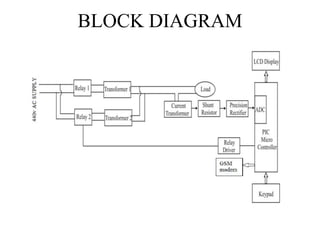
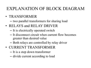
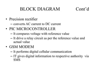
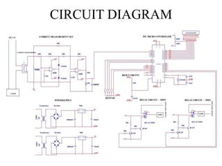
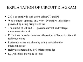
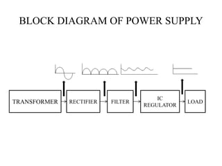
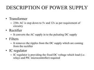
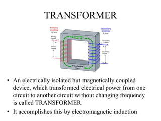
SlideShare a Scribd company logo
1 of 38
K.D.K COLLEGE OF ENGINEERING
NAGPUR.
PROJECT SEMINAR
ON
“AUTOMATIC LOAD SHARING OF TRANSFORMERS
USING GSM TECHNIQUE”
• projectee- NIKHIL S HIWAREGUIDED BY:
Prof. A. W. Pardhi sir
DEPARTMENT OF ELECTRONICS AND TELECOMMUNICATION ENGINEERING
SESSION – 2012-2013
CONTENTS
• INTRODUCTION
• OVERVIEW OF PREVIOUS SEMINAR
• OBJECTIVES
• BLOCK DIAGRAM
• CIRCUIT DIAGRAM
• POWER SUPPLY
• TRANSFORMER
• RECTIFIER
• BRIDGE RECTIFIER
• FILTERS
• IC REGULATOR
• PIC MICROCONTROLLER
• VOLTAGE MEASUREMENT
• CURRENT MEASUREMENT
• RELAYS
• CIRCUIT LAYOUT
• ADVANTAGES & DISADVANTAGES
• FUTURE SCOPE
• REFERENCES
• THANKYOU
INTRODUCTION
• The Project is all about the protecting transformer under
overload condition.
• Drop in efficiency and overheating in secondary
winding can be prevented with the help of this project.
• Load sharing of the transformer is possible with the
help of this project theme and the life of the transformer
is increased.
• The project is also used as a Un-interrupted power
supply (UPS)
• If short circuit fault is occurs the transformer will get
protected.
OVERVIEW OF PREVIOUS SEMINAR
• PIC Microcontroller
• Transformers
• Precision rectifiers
• Current transformer
• Voltage transformer
• Relay driver circuit with relays
• GSM
OBJECTIVES
• The main aim of the project is transformer sharing
whenever load is increased for certain value and also
sending this change in information to the respective
authority via SMS by using GSM modem
• The objective of this project is to protect the
Domestic supply and Power Transformers from over
load power.
BLOCK DIAGRAM
EXPLANATION OF BLOCK DIAGRAM
• TRANSFORMER
– two parallel transformers for sharing load
• RELAYS and RELAY DRIVER
– It is electrically operated switch
– It disconnect circuit when current flow becomes
greater than desired value
– Both relays are controlled by relay driver
• CURRENT TRANSFORMER
– It is a step down transformer
– divide current according to load
BLOCK DIAGRAM Cont’d
• Precision rectifier
– converts AC current to DC current
• PIC MICROCONTROLLER
– It compares voltage with reference value
– It drive a relay circuit as per the reference value and
actual value
• GSM MODEM
– It performs digital cellular communication
– IT gives digital information to respective authority via
SMS
CIRCUIT DIAGRAM
EXPLANATION OF CIRCUIT DIAGRAM
• 230 v ac supply is step down using CT and PT
• Whole circuit operates on 5 v or 12v supply, this supply
provided by using bridge rectifier
• The output of CT and PT given to current and voltage
measurement circuit
• PIC microcontroller compares the output of both circuits with
reference value
• Reference value are given by using keypad to the
microcontroller
• Relay are operated by PIC microcontroller
• LCD displays the value of load
PARTS OF CIRCUIT
• Power supply
• PIC microcontroller
• Current measurement
• Voltage measurement
• Relay
POWER SUPPLY
• Whole circuitry work on +5v,+12v & -12v DC power
• Supply of 230v AC is applied to the transformer
• By using transformer, rectifier, filters, IC regulators
etc. we get the desired output
TRANSFORMER RECTIFIER FILTER
IC
REGULATOR
LOAD
BLOCK DIAGRAM OF POWER SUPPLY
DESCRIPTION OF POWER SUPPLY
• Transformer
– 230v AC is step down to 5v and 12v as per requirement of
circuitry
• Rectifier
– It converts the AC supply in to the pulsating DC supply
• Filters
– It removes the ripples from the DC supply which are coming
from the rectifier
• IC regulator
– IC regulator is providing the fixed DC voltage which load (i.e.
relays and PIC microcontroller) required
TRANSFORMER
• An electrically isolated but magnetically coupled
device, which transformed electrical power from one
circuit to another circuit without changing frequency
is called TRANSFORMER
• It accomplishes this by electromagnetic induction
TRANSFORMER Cont’d
• There are basically two types
– Step Down transformer
– Step Up transformer
• We are using step down transformer
• CT and PT are step down transformer
RECTIFIER
• It is a circuit which converts AC to DC
• Output of a rectifier is not pure DC, it is pulsating DC
• There are basically two types of rectifier
– Half wave rectifier
– Full wave rectifier
• Bridge rectifier
• We are using Bridge rectifier to get desired DC output
voltage of +5v,+12v and -12v
BRIDGE RECTIFIER
230VAC
P S
0
9
D1 D2
D3 D4
4*1N4007
1000mF
25V 10mF
25V
7805
1
2
3
+
-
GND
+5V/500mA
+5V POWER SUPPLY
+
-
230VAC
P S
D4
4*1N4007
25V
25V
25V
25V
1000mF
1000mF
10mF
10mF
1
2
21 3
3
D1 D2
D3
- -
--
+ +
++
GND
+12V
-12V
7812
7912
15
15
+12V AND -12V POWER SUPPLY
Circuit Diagram (Power Supply)
a
b
c d
d
a
b
c
WORKING OF BRIDGE RECTIFIER
• At +ve half cycle there is +ve potential at node A and –ve
potential at node B
• Due to which D1 and D4 are in forward bias and D2 and
D3 are work in reverse bias, we get DC voltage of +ve
half cycle
• Similarly at -ve half cycle there is +ve potential at node B
and –ve potential at node A
• Due to which D2 and D3 are in forward bias and D1 and
D4 are work in reverse bias, we get DC voltage of -ve
half cycle
• When the operation of full wave bridge rectifier is
complete, we get output that is pulsating DC.
FILTERS
• An element or device which removes unwanted
signals from the supply is called as filters
• Rectifier output is in the form of pulsating DC which
contain certain ripples
• To remove this ripples and to get pure DC supply
filters are used
• In Bridge rectifier capacitor works as filter which
removes AC ripple components from the rectifier
output
IC REGULATOR
IC REGULATOR Cont’d
• Regulator IC is the IC which provides the fixed
voltage to the different components even if the input
of the regulator IC is vary
• Regulator IC units contain the circuitry for reference
source, comparator amplifier, control device, and
overload protection all in a single IC
• In our project we are using 7805,7812,7912 IC
regulator
PIC MICROCONTROLLER
• PIC stand for programmable interrupt controller
• PICs are popular for low cost, wide availability, large
user base, free development tools and serial
programming (and reprogramming with flash
memory) capability so we are using PIC
microcontroller
• PIC microcontroller is the first RISC base
microcontroller
PIN CONFIGURATION OF MICROCONTROLLER
PIC MICROCONTROLLER
•Pin no 3-current measurement
•The output of current measurements are given to microcontroller through
this pin
•According to the measurement microcontroller giving the signal to
various component of the circuit
•Pin no 8,9,10,18,23-keypad
•Keypad is connected through the microcontroller via this pins
•The reference values of current and voltages through keypad to
microcontroller
•Pin no 1-reset
•The microcontrollers data is reset via this pins
•Pin no 12,31-gnd
•This pins are connected to the ground
PIC MICROCONTROLLER Cont’d
• Pin no 13,14-crystal oscillator
• Crystal oscillator generates about 1200MHZ of frequency
which is called oscillating frequency
• Microcontroller works on oscillating frequency
• Pin no 33,34-realy circuit
• Relays are operated via this pins of microcontroller
• Pin no 19,20,21,22,27,28,29,30-LCD
• This pins of microcontroller are given to the LCD display
unit
• LCD display the load values
• Pin no 11,32-VCC
• Fixed voltage is given to the microcontroller via this pins
VOLTAGE MEASUREMENT
VOLTAGE MEASUREMENT Cont’d
• Potential transformer(PT) is use to monitor the
supply voltage
• Supply voltage that has to be monitor is step
down by PT
• The step down voltage is rectified by bridge
rectifier
• Different DC voltage which required by relay and
PIC are to be given by using IC regulator
• The function of voltage measurement is to
provide step down voltage
CURRENT MEASUREMENT
CURRENT MEASUREMENT Cont’d
• Current transformer(CT) is use to step down
current
• The circuit is design to monitor the supply
current
• The step down current is converted by voltage
with the help of shunt register
RELAYS
RELAYS Cont’d
• It is an electromagnetic device which is use as switch
• it has a magnetic coil which is use to connect or
disconnect the transformer
• It is electrically operated switch
• It disconnect circuit when current flow becomes greater
than desired value
• Both relays are controlled by relay driver
• If the current consumption is above 50% then the lower
relay get switch OFF through the relay driver circuit.
• IF the current consumption is above 80% then the all
relay get switch OFF through the relay driver circuit.
CIRCUIT LAYOUT
ADVANTAGES
• It prevents circuitry from damage
• Avoid interruption in power supply
• Remove power black out at pick hours
• Accident prevention
• Transformer safety
DISADVANTAGES
• Cost of whole circuitry will increased
• Circuitry become bulky
FUTURE SCOPE
• GSM-(global system for mobile
communication)
– GSM is globally accepted standard for digital
cellular communication
– Frequency range 900MHZ to 1990MHZ
– PIC microcontroller sends actual load value to the
authority via SMS by using GSM
– In our project we are using only transmitter to
transmit the data
– In our project we are not yet get the required
frequency GSM
REFERENCES
• Electrical technology volume 3rd and 4th by- B. L.
Theraja,1st edition 1959,reprint 2008
• Advance microprocessor and microcontrollers by-
A. P. Godse,3rd edition 2003
• Linear integrated circuits J.S. Katre, 4th edition
2002
• IEEE Transaction on Power Electronics, vol. 19,
no. 6, November 2004 1551by-Mohammad N.
Marwali, Member, IEEE, Jin-Woo Jung, Student
Member, IEEE, and Ali Keyhani, Fellow, IEEE
THANK YOU

More Related Content

What's hot

Objectives of shunt compensation
Objectives of shunt compensationObjectives of shunt compensation
Objectives of shunt compensationAyyarao T S L V
 
BUSBAR PROTECTION
BUSBAR PROTECTIONBUSBAR PROTECTION
BUSBAR PROTECTIONDinesh Sarda
 
Distribution and Load Sharing of Transformer Automatically by using Microcont...
Distribution and Load Sharing of Transformer Automatically by using Microcont...Distribution and Load Sharing of Transformer Automatically by using Microcont...
Distribution and Load Sharing of Transformer Automatically by using Microcont...IRJET Journal
 
Protective relay
Protective relay Protective relay
Protective relay Uday Wankar
 
Unit-2 Three Phase controlled converter
Unit-2 Three Phase controlled converter Unit-2 Three Phase controlled converter
Unit-2 Three Phase controlled converter johny renoald
 
Thyristor switched capacitor
Thyristor switched capacitorThyristor switched capacitor
Thyristor switched capacitorKLS' S GIT, BELGAUM
 
132KV SUBSTATION UPPTCL
132KV SUBSTATION UPPTCL132KV SUBSTATION UPPTCL
132KV SUBSTATION UPPTCLAman Rajput
 
Unit 03 Protective relays
Unit  03 Protective relaysUnit  03 Protective relays
Unit 03 Protective relaysPremanandDesai
 
Electrical substations: 132 KV
Electrical substations: 132 KV Electrical substations: 132 KV
Electrical substations: 132 KV Girish Gupta
 
ppt of Three phase fault analysis with auto reset for temporary fault and tri...
ppt of Three phase fault analysis with auto reset for temporary fault and tri...ppt of Three phase fault analysis with auto reset for temporary fault and tri...
ppt of Three phase fault analysis with auto reset for temporary fault and tri...Vikram Rawani
 
PPT on 33/11 sub-station uppcl
PPT on 33/11 sub-station uppclPPT on 33/11 sub-station uppcl
PPT on 33/11 sub-station uppclVISHAL VERMA
 
Ac voltage controller
Ac voltage controllerAc voltage controller
Ac voltage controllerJosin Hippolitus
 
220KV Substation Training Report
220KV Substation Training Report220KV Substation Training Report
220KV Substation Training ReportSWAPNILKUMARGUPTA
 
Buck-Boost Converter
Buck-Boost ConverterBuck-Boost Converter
Buck-Boost ConverterSagar Patil
 
Power electronics Phase Controlled Rectifiers - SCR
Power electronics   Phase Controlled Rectifiers - SCRPower electronics   Phase Controlled Rectifiers - SCR
Power electronics Phase Controlled Rectifiers - SCRBurdwan University
 
substation internship report
substation internship report substation internship report
substation internship report Arun Thapa
 
Power Electronics Chopper (dc – dc converter)
Power Electronics   Chopper (dc – dc converter)Power Electronics   Chopper (dc – dc converter)
Power Electronics Chopper (dc – dc converter)Burdwan University
 
Presentation on 132/33 KVSubstation Training
Presentation on 132/33 KVSubstation Training Presentation on 132/33 KVSubstation Training
Presentation on 132/33 KVSubstation Training Sakshi Rastogi
 

What's hot (20)

Objectives of shunt compensation
Objectives of shunt compensationObjectives of shunt compensation
Objectives of shunt compensation
 
BUSBAR PROTECTION
BUSBAR PROTECTIONBUSBAR PROTECTION
BUSBAR PROTECTION
 
Distribution and Load Sharing of Transformer Automatically by using Microcont...
Distribution and Load Sharing of Transformer Automatically by using Microcont...Distribution and Load Sharing of Transformer Automatically by using Microcont...
Distribution and Load Sharing of Transformer Automatically by using Microcont...
 
Protective relay
Protective relay Protective relay
Protective relay
 
Unit-2 Three Phase controlled converter
Unit-2 Three Phase controlled converter Unit-2 Three Phase controlled converter
Unit-2 Three Phase controlled converter
 
Thyristor switched capacitor
Thyristor switched capacitorThyristor switched capacitor
Thyristor switched capacitor
 
132KV SUBSTATION UPPTCL
132KV SUBSTATION UPPTCL132KV SUBSTATION UPPTCL
132KV SUBSTATION UPPTCL
 
Unit 03 Protective relays
Unit  03 Protective relaysUnit  03 Protective relays
Unit 03 Protective relays
 
Electrical substations: 132 KV
Electrical substations: 132 KV Electrical substations: 132 KV
Electrical substations: 132 KV
 
ppt of Three phase fault analysis with auto reset for temporary fault and tri...
ppt of Three phase fault analysis with auto reset for temporary fault and tri...ppt of Three phase fault analysis with auto reset for temporary fault and tri...
ppt of Three phase fault analysis with auto reset for temporary fault and tri...
 
PPT on 33/11 sub-station uppcl
PPT on 33/11 sub-station uppclPPT on 33/11 sub-station uppcl
PPT on 33/11 sub-station uppcl
 
Reactive power
Reactive powerReactive power
Reactive power
 
Ac voltage controller
Ac voltage controllerAc voltage controller
Ac voltage controller
 
220KV Substation Training Report
220KV Substation Training Report220KV Substation Training Report
220KV Substation Training Report
 
Buck-Boost Converter
Buck-Boost ConverterBuck-Boost Converter
Buck-Boost Converter
 
Power electronics Phase Controlled Rectifiers - SCR
Power electronics   Phase Controlled Rectifiers - SCRPower electronics   Phase Controlled Rectifiers - SCR
Power electronics Phase Controlled Rectifiers - SCR
 
132 33kv substation
132 33kv substation132 33kv substation
132 33kv substation
 
substation internship report
substation internship report substation internship report
substation internship report
 
Power Electronics Chopper (dc – dc converter)
Power Electronics   Chopper (dc – dc converter)Power Electronics   Chopper (dc – dc converter)
Power Electronics Chopper (dc – dc converter)
 
Presentation on 132/33 KVSubstation Training
Presentation on 132/33 KVSubstation Training Presentation on 132/33 KVSubstation Training
Presentation on 132/33 KVSubstation Training
 

Viewers also liked

Transformers seminar
Transformers seminarTransformers seminar
Transformers seminarvinayvickky
 
MATLAB Simulink for single phase PWM inverter in an uninterrupted power supply
MATLAB Simulink for single phase PWM inverter in an  uninterrupted power supplyMATLAB Simulink for single phase PWM inverter in an  uninterrupted power supply
MATLAB Simulink for single phase PWM inverter in an uninterrupted power supplyIJMER
 
Single Phase to Three Phase Converter
Single Phase to Three Phase Converter Single Phase to Three Phase Converter
Single Phase to Three Phase Converter Devesh Gupta
 
Cd te solar cell
Cd te solar cellCd te solar cell
Cd te solar cellSubhasis Shit
 
Harmonics analysis of single phase inverter
Harmonics analysis of single phase inverterHarmonics analysis of single phase inverter
Harmonics analysis of single phase inverterBINOD PATEL
 
Transformers Project report
Transformers Project reportTransformers Project report
Transformers Project reportTanuj Gupta
 
Small Cap Trade Options Minimum $2 Million
Small Cap Trade Options Minimum $2 MillionSmall Cap Trade Options Minimum $2 Million
Small Cap Trade Options Minimum $2 MillionVimal Kharbanda
 
Leased Instrument Application R (1)
Leased Instrument Application R (1)Leased Instrument Application R (1)
Leased Instrument Application R (1)jose Anaya
 
Trade ppp investment programs
Trade ppp investment programsTrade ppp investment programs
Trade ppp investment programsMJK INC
 
What is proof of funds (pof) & where to use it
What is proof of funds (pof) & where to use itWhat is proof of funds (pof) & where to use it
What is proof of funds (pof) & where to use itBanks Instruments
 
Shelf Offshore Company + HSBC HK account for sale
Shelf Offshore Company + HSBC HK account for saleShelf Offshore Company + HSBC HK account for sale
Shelf Offshore Company + HSBC HK account for saleOffshore Premium
 
Introdution to POF reliability methods
Introdution to POF reliability methodsIntrodution to POF reliability methods
Introdution to POF reliability methodsASQ Reliability Division
 

Viewers also liked (20)

Transformers seminar
Transformers seminarTransformers seminar
Transformers seminar
 
MATLAB Simulink for single phase PWM inverter in an uninterrupted power supply
MATLAB Simulink for single phase PWM inverter in an  uninterrupted power supplyMATLAB Simulink for single phase PWM inverter in an  uninterrupted power supply
MATLAB Simulink for single phase PWM inverter in an uninterrupted power supply
 
Presentation11
Presentation11Presentation11
Presentation11
 
Single Phase to Three Phase Converter
Single Phase to Three Phase Converter Single Phase to Three Phase Converter
Single Phase to Three Phase Converter
 
solar cell
solar cellsolar cell
solar cell
 
Cd te solar cell
Cd te solar cellCd te solar cell
Cd te solar cell
 
Harmonics analysis of single phase inverter
Harmonics analysis of single phase inverterHarmonics analysis of single phase inverter
Harmonics analysis of single phase inverter
 
Transformer construction,types and working
Transformer construction,types and workingTransformer construction,types and working
Transformer construction,types and working
 
Transformers Project report
Transformers Project reportTransformers Project report
Transformers Project report
 
12. POF
12. POF12. POF
12. POF
 
Small Cap Trade Options Minimum $2 Million
Small Cap Trade Options Minimum $2 MillionSmall Cap Trade Options Minimum $2 Million
Small Cap Trade Options Minimum $2 Million
 
Leased Instrument Application R (1)
Leased Instrument Application R (1)Leased Instrument Application R (1)
Leased Instrument Application R (1)
 
Trade ppp investment programs
Trade ppp investment programsTrade ppp investment programs
Trade ppp investment programs
 
What is proof of funds (pof) & where to use it
What is proof of funds (pof) & where to use itWhat is proof of funds (pof) & where to use it
What is proof of funds (pof) & where to use it
 
Shelf Offshore Company + HSBC HK account for sale
Shelf Offshore Company + HSBC HK account for saleShelf Offshore Company + HSBC HK account for sale
Shelf Offshore Company + HSBC HK account for sale
 
PROCEDURE
PROCEDUREPROCEDURE
PROCEDURE
 
POF
POFPOF
POF
 
transformer ppt
transformer ppttransformer ppt
transformer ppt
 
Introdution to POF reliability methods
Introdution to POF reliability methodsIntrodution to POF reliability methods
Introdution to POF reliability methods
 
Procedure
ProcedureProcedure
Procedure
 

Similar to MY PROJECT-automatic load sharing of transformer by using GSM tecnique.

Transformer protection using microcontroller and gsm technology
Transformer protection using microcontroller and gsm technologyTransformer protection using microcontroller and gsm technology
Transformer protection using microcontroller and gsm technologyKartik Patel
 
voltage doubler using 555 timer ic
voltage doubler using 555 timer ic voltage doubler using 555 timer ic
voltage doubler using 555 timer ic afzalvp99
 
Intelligent Street light monitoring system
Intelligent Street light monitoring systemIntelligent Street light monitoring system
Intelligent Street light monitoring systemvikas mantri
 
SOLID STATE TRANSFORMER - USING FLYBACK CONVERTER
SOLID STATE TRANSFORMER - USING FLYBACK CONVERTERSOLID STATE TRANSFORMER - USING FLYBACK CONVERTER
SOLID STATE TRANSFORMER - USING FLYBACK CONVERTERAbhin Mohan
 
lecture 10 - electrical machines - dc to dc converters 1.pptx
lecture 10 - electrical machines - dc to dc converters 1.pptxlecture 10 - electrical machines - dc to dc converters 1.pptx
lecture 10 - electrical machines - dc to dc converters 1.pptxJohnkamanda3
 
HOME APPLICATION REGULATION USING TV REMOTE
HOME APPLICATION REGULATION USING TV REMOTEHOME APPLICATION REGULATION USING TV REMOTE
HOME APPLICATION REGULATION USING TV REMOTEshiv kapil
 
Doc speed control of a dc motor using micro controller 8051
Doc speed control of a dc motor using micro controller 8051Doc speed control of a dc motor using micro controller 8051
Doc speed control of a dc motor using micro controller 8051embdnew
 
Smart metering and conditional access control of electrical energy
Smart metering and conditional access control of electrical energySmart metering and conditional access control of electrical energy
Smart metering and conditional access control of electrical energykannansenthilkumar
 
IRJET- Technique to Prevent Power Theft Losses using Static Device
IRJET-  	  Technique to Prevent Power Theft Losses using Static DeviceIRJET-  	  Technique to Prevent Power Theft Losses using Static Device
IRJET- Technique to Prevent Power Theft Losses using Static DeviceIRJET Journal
 
AUTOMATIC THREE PHASE SUPPLY CHANGOVER
AUTOMATIC THREE PHASE SUPPLY CHANGOVERAUTOMATIC THREE PHASE SUPPLY CHANGOVER
AUTOMATIC THREE PHASE SUPPLY CHANGOVERshiv kapil
 
Chapter 1 Introduction to power Electronic Devices.pdf
Chapter 1 Introduction to power Electronic Devices.pdfChapter 1 Introduction to power Electronic Devices.pdf
Chapter 1 Introduction to power Electronic Devices.pdfLiewChiaPing
 
Automatic mall elevator
Automatic mall elevatorAutomatic mall elevator
Automatic mall elevatorAbhilash Dhatrak
 
Basic Protection of transformer using microcontroller based relay
Basic Protection of transformer using microcontroller based relayBasic Protection of transformer using microcontroller based relay
Basic Protection of transformer using microcontroller based relaySatish Dharpure
 
Substation monitoring1
Substation monitoring1Substation monitoring1
Substation monitoring1buckky
 
GSS ppt
GSS pptGSS ppt
GSS pptravi kant
 
REGULATED_POWER_SUPPLY-1[1].pptx
REGULATED_POWER_SUPPLY-1[1].pptxREGULATED_POWER_SUPPLY-1[1].pptx
REGULATED_POWER_SUPPLY-1[1].pptxPratikJoshi123
 
Extra high voltage long ac transmission lines
Extra high voltage long ac transmission linesExtra high voltage long ac transmission lines
Extra high voltage long ac transmission linesShivagee Raj
 
Electric-Traction-Railways.ppt
Electric-Traction-Railways.pptElectric-Traction-Railways.ppt
Electric-Traction-Railways.pptssuserf805c8
 

Similar to MY PROJECT-automatic load sharing of transformer by using GSM tecnique. (20)

Transformer protection using microcontroller and gsm technology
Transformer protection using microcontroller and gsm technologyTransformer protection using microcontroller and gsm technology
Transformer protection using microcontroller and gsm technology
 
voltage doubler using 555 timer ic
voltage doubler using 555 timer ic voltage doubler using 555 timer ic
voltage doubler using 555 timer ic
 
Intelligent Street light monitoring system
Intelligent Street light monitoring systemIntelligent Street light monitoring system
Intelligent Street light monitoring system
 
SOLID STATE TRANSFORMER - USING FLYBACK CONVERTER
SOLID STATE TRANSFORMER - USING FLYBACK CONVERTERSOLID STATE TRANSFORMER - USING FLYBACK CONVERTER
SOLID STATE TRANSFORMER - USING FLYBACK CONVERTER
 
lecture 10 - electrical machines - dc to dc converters 1.pptx
lecture 10 - electrical machines - dc to dc converters 1.pptxlecture 10 - electrical machines - dc to dc converters 1.pptx
lecture 10 - electrical machines - dc to dc converters 1.pptx
 
HOME APPLICATION REGULATION USING TV REMOTE
HOME APPLICATION REGULATION USING TV REMOTEHOME APPLICATION REGULATION USING TV REMOTE
HOME APPLICATION REGULATION USING TV REMOTE
 
Doc speed control of a dc motor using micro controller 8051
Doc speed control of a dc motor using micro controller 8051Doc speed control of a dc motor using micro controller 8051
Doc speed control of a dc motor using micro controller 8051
 
Smart metering and conditional access control of electrical energy
Smart metering and conditional access control of electrical energySmart metering and conditional access control of electrical energy
Smart metering and conditional access control of electrical energy
 
Ppt iitr
Ppt iitrPpt iitr
Ppt iitr
 
seminar.pptx
seminar.pptxseminar.pptx
seminar.pptx
 
IRJET- Technique to Prevent Power Theft Losses using Static Device
IRJET-  	  Technique to Prevent Power Theft Losses using Static DeviceIRJET-  	  Technique to Prevent Power Theft Losses using Static Device
IRJET- Technique to Prevent Power Theft Losses using Static Device
 
AUTOMATIC THREE PHASE SUPPLY CHANGOVER
AUTOMATIC THREE PHASE SUPPLY CHANGOVERAUTOMATIC THREE PHASE SUPPLY CHANGOVER
AUTOMATIC THREE PHASE SUPPLY CHANGOVER
 
Chapter 1 Introduction to power Electronic Devices.pdf
Chapter 1 Introduction to power Electronic Devices.pdfChapter 1 Introduction to power Electronic Devices.pdf
Chapter 1 Introduction to power Electronic Devices.pdf
 
Automatic mall elevator
Automatic mall elevatorAutomatic mall elevator
Automatic mall elevator
 
Basic Protection of transformer using microcontroller based relay
Basic Protection of transformer using microcontroller based relayBasic Protection of transformer using microcontroller based relay
Basic Protection of transformer using microcontroller based relay
 
Substation monitoring1
Substation monitoring1Substation monitoring1
Substation monitoring1
 
GSS ppt
GSS pptGSS ppt
GSS ppt
 
REGULATED_POWER_SUPPLY-1[1].pptx
REGULATED_POWER_SUPPLY-1[1].pptxREGULATED_POWER_SUPPLY-1[1].pptx
REGULATED_POWER_SUPPLY-1[1].pptx
 
Extra high voltage long ac transmission lines
Extra high voltage long ac transmission linesExtra high voltage long ac transmission lines
Extra high voltage long ac transmission lines
 
Electric-Traction-Railways.ppt
Electric-Traction-Railways.pptElectric-Traction-Railways.ppt
Electric-Traction-Railways.ppt
 

Recently uploaded

PSYCHIATRIC History collection FORMAT.pptx
PSYCHIATRIC   History collection FORMAT.pptxPSYCHIATRIC   History collection FORMAT.pptx
PSYCHIATRIC History collection FORMAT.pptxPoojaSen20
 
Crayon Activity Handout For the Crayon A
Crayon Activity Handout For the Crayon ACrayon Activity Handout For the Crayon A
Crayon Activity Handout For the Crayon AUnboundStockton
 
Accessible design: Minimum effort, maximum impact
Accessible design: Minimum effort, maximum impactAccessible design: Minimum effort, maximum impact
Accessible design: Minimum effort, maximum impactdawncurless
 
How to Make a Pirate ship Primary Education.pptx
How to Make a Pirate ship Primary Education.pptxHow to Make a Pirate ship Primary Education.pptx
How to Make a Pirate ship Primary Education.pptxmanuelaromero2013
 
Solving Puzzles Benefits Everyone (English).pptx
Solving Puzzles Benefits Everyone (English).pptxSolving Puzzles Benefits Everyone (English).pptx
Solving Puzzles Benefits Everyone (English).pptxOH TEIK BIN
 
SOCIAL AND HISTORICAL CONTEXT - LFTVD.pptx
SOCIAL AND HISTORICAL CONTEXT - LFTVD.pptxSOCIAL AND HISTORICAL CONTEXT - LFTVD.pptx
SOCIAL AND HISTORICAL CONTEXT - LFTVD.pptxiammrhaywood
 
Organic Name Reactions for the students and aspirants of Chemistry12th.pptx
Organic Name Reactions  for the students and aspirants of Chemistry12th.pptxOrganic Name Reactions  for the students and aspirants of Chemistry12th.pptx
Organic Name Reactions for the students and aspirants of Chemistry12th.pptxVS Mahajan Coaching Centre
 
Separation of Lanthanides/ Lanthanides and Actinides
Separation of Lanthanides/ Lanthanides and ActinidesSeparation of Lanthanides/ Lanthanides and Actinides
Separation of Lanthanides/ Lanthanides and ActinidesFatimaKhan178732
 
Presiding Officer Training module 2024 lok sabha elections
Presiding Officer Training module 2024 lok sabha electionsPresiding Officer Training module 2024 lok sabha elections
Presiding Officer Training module 2024 lok sabha electionsanshu789521
 
Arihant handbook biology for class 11 .pdf
Arihant handbook biology for class 11 .pdfArihant handbook biology for class 11 .pdf
Arihant handbook biology for class 11 .pdfchloefrazer622
 
Measures of Central Tendency: Mean, Median and Mode
Measures of Central Tendency: Mean, Median and ModeMeasures of Central Tendency: Mean, Median and Mode
Measures of Central Tendency: Mean, Median and ModeThiyagu K
 
Call Girls in Dwarka Mor Delhi Contact Us 9654467111
Call Girls in Dwarka Mor Delhi Contact Us 9654467111Call Girls in Dwarka Mor Delhi Contact Us 9654467111
Call Girls in Dwarka Mor Delhi Contact Us 9654467111Sapana Sha
 
Employee wellbeing at the workplace.pptx
Employee wellbeing at the workplace.pptxEmployee wellbeing at the workplace.pptx
Employee wellbeing at the workplace.pptxNirmalaLoungPoorunde1
 
URLs and Routing in the Odoo 17 Website App
URLs and Routing in the Odoo 17 Website AppURLs and Routing in the Odoo 17 Website App
URLs and Routing in the Odoo 17 Website AppCeline George
 
Micromeritics - Fundamental and Derived Properties of Powders
Micromeritics - Fundamental and Derived Properties of PowdersMicromeritics - Fundamental and Derived Properties of Powders
Micromeritics - Fundamental and Derived Properties of PowdersChitralekhaTherkar
 
Concept of Vouching. B.Com(Hons) /B.Compdf
Concept of Vouching. B.Com(Hons) /B.CompdfConcept of Vouching. B.Com(Hons) /B.Compdf
Concept of Vouching. B.Com(Hons) /B.CompdfUmakantAnnand
 
The Most Excellent Way | 1 Corinthians 13
The Most Excellent Way | 1 Corinthians 13The Most Excellent Way | 1 Corinthians 13
The Most Excellent Way | 1 Corinthians 13Steve Thomason
 

Recently uploaded (20)

PSYCHIATRIC History collection FORMAT.pptx
PSYCHIATRIC   History collection FORMAT.pptxPSYCHIATRIC   History collection FORMAT.pptx
PSYCHIATRIC History collection FORMAT.pptx
 
Crayon Activity Handout For the Crayon A
Crayon Activity Handout For the Crayon ACrayon Activity Handout For the Crayon A
Crayon Activity Handout For the Crayon A
 
Accessible design: Minimum effort, maximum impact
Accessible design: Minimum effort, maximum impactAccessible design: Minimum effort, maximum impact
Accessible design: Minimum effort, maximum impact
 
How to Make a Pirate ship Primary Education.pptx
How to Make a Pirate ship Primary Education.pptxHow to Make a Pirate ship Primary Education.pptx
How to Make a Pirate ship Primary Education.pptx
 
Solving Puzzles Benefits Everyone (English).pptx
Solving Puzzles Benefits Everyone (English).pptxSolving Puzzles Benefits Everyone (English).pptx
Solving Puzzles Benefits Everyone (English).pptx
 
Model Call Girl in Bikash Puri Delhi reach out to us at 🔝9953056974🔝
Model Call Girl in Bikash Puri  Delhi reach out to us at 🔝9953056974🔝Model Call Girl in Bikash Puri  Delhi reach out to us at 🔝9953056974🔝
Model Call Girl in Bikash Puri Delhi reach out to us at 🔝9953056974🔝
 
SOCIAL AND HISTORICAL CONTEXT - LFTVD.pptx
SOCIAL AND HISTORICAL CONTEXT - LFTVD.pptxSOCIAL AND HISTORICAL CONTEXT - LFTVD.pptx
SOCIAL AND HISTORICAL CONTEXT - LFTVD.pptx
 
Organic Name Reactions for the students and aspirants of Chemistry12th.pptx
Organic Name Reactions  for the students and aspirants of Chemistry12th.pptxOrganic Name Reactions  for the students and aspirants of Chemistry12th.pptx
Organic Name Reactions for the students and aspirants of Chemistry12th.pptx
 
TataKelola dan KamSiber Kecerdasan Buatan v022.pdf
TataKelola dan KamSiber Kecerdasan Buatan v022.pdfTataKelola dan KamSiber Kecerdasan Buatan v022.pdf
TataKelola dan KamSiber Kecerdasan Buatan v022.pdf
 
CĂłdigo Creativo y Arte de Software | Unidad 1
CĂłdigo Creativo y Arte de Software | Unidad 1CĂłdigo Creativo y Arte de Software | Unidad 1
CĂłdigo Creativo y Arte de Software | Unidad 1
 
Separation of Lanthanides/ Lanthanides and Actinides
Separation of Lanthanides/ Lanthanides and ActinidesSeparation of Lanthanides/ Lanthanides and Actinides
Separation of Lanthanides/ Lanthanides and Actinides
 
Presiding Officer Training module 2024 lok sabha elections
Presiding Officer Training module 2024 lok sabha electionsPresiding Officer Training module 2024 lok sabha elections
Presiding Officer Training module 2024 lok sabha elections
 
Arihant handbook biology for class 11 .pdf
Arihant handbook biology for class 11 .pdfArihant handbook biology for class 11 .pdf
Arihant handbook biology for class 11 .pdf
 
Measures of Central Tendency: Mean, Median and Mode
Measures of Central Tendency: Mean, Median and ModeMeasures of Central Tendency: Mean, Median and Mode
Measures of Central Tendency: Mean, Median and Mode
 
Call Girls in Dwarka Mor Delhi Contact Us 9654467111
Call Girls in Dwarka Mor Delhi Contact Us 9654467111Call Girls in Dwarka Mor Delhi Contact Us 9654467111
Call Girls in Dwarka Mor Delhi Contact Us 9654467111
 
Employee wellbeing at the workplace.pptx
Employee wellbeing at the workplace.pptxEmployee wellbeing at the workplace.pptx
Employee wellbeing at the workplace.pptx
 
URLs and Routing in the Odoo 17 Website App
URLs and Routing in the Odoo 17 Website AppURLs and Routing in the Odoo 17 Website App
URLs and Routing in the Odoo 17 Website App
 
Micromeritics - Fundamental and Derived Properties of Powders
Micromeritics - Fundamental and Derived Properties of PowdersMicromeritics - Fundamental and Derived Properties of Powders
Micromeritics - Fundamental and Derived Properties of Powders
 
Concept of Vouching. B.Com(Hons) /B.Compdf
Concept of Vouching. B.Com(Hons) /B.CompdfConcept of Vouching. B.Com(Hons) /B.Compdf
Concept of Vouching. B.Com(Hons) /B.Compdf
 
The Most Excellent Way | 1 Corinthians 13
The Most Excellent Way | 1 Corinthians 13The Most Excellent Way | 1 Corinthians 13
The Most Excellent Way | 1 Corinthians 13
 

MY PROJECT-automatic load sharing of transformer by using GSM tecnique.

  • 1. K.D.K COLLEGE OF ENGINEERING NAGPUR. PROJECT SEMINAR ON “AUTOMATIC LOAD SHARING OF TRANSFORMERS USING GSM TECHNIQUE” • projectee- NIKHIL S HIWAREGUIDED BY: Prof. A. W. Pardhi sir DEPARTMENT OF ELECTRONICS AND TELECOMMUNICATION ENGINEERING SESSION – 2012-2013
  • 2. CONTENTS • INTRODUCTION • OVERVIEW OF PREVIOUS SEMINAR • OBJECTIVES • BLOCK DIAGRAM • CIRCUIT DIAGRAM • POWER SUPPLY • TRANSFORMER • RECTIFIER • BRIDGE RECTIFIER • FILTERS • IC REGULATOR • PIC MICROCONTROLLER • VOLTAGE MEASUREMENT • CURRENT MEASUREMENT • RELAYS • CIRCUIT LAYOUT • ADVANTAGES & DISADVANTAGES • FUTURE SCOPE • REFERENCES • THANKYOU
  • 3. INTRODUCTION • The Project is all about the protecting transformer under overload condition. • Drop in efficiency and overheating in secondary winding can be prevented with the help of this project. • Load sharing of the transformer is possible with the help of this project theme and the life of the transformer is increased. • The project is also used as a Un-interrupted power supply (UPS) • If short circuit fault is occurs the transformer will get protected.
  • 4. OVERVIEW OF PREVIOUS SEMINAR • PIC Microcontroller • Transformers • Precision rectifiers • Current transformer • Voltage transformer • Relay driver circuit with relays • GSM
  • 5. OBJECTIVES • The main aim of the project is transformer sharing whenever load is increased for certain value and also sending this change in information to the respective authority via SMS by using GSM modem • The objective of this project is to protect the Domestic supply and Power Transformers from over load power.
  • 7. EXPLANATION OF BLOCK DIAGRAM • TRANSFORMER – two parallel transformers for sharing load • RELAYS and RELAY DRIVER – It is electrically operated switch – It disconnect circuit when current flow becomes greater than desired value – Both relays are controlled by relay driver • CURRENT TRANSFORMER – It is a step down transformer – divide current according to load
  • 8. BLOCK DIAGRAM Cont’d • Precision rectifier – converts AC current to DC current • PIC MICROCONTROLLER – It compares voltage with reference value – It drive a relay circuit as per the reference value and actual value • GSM MODEM – It performs digital cellular communication – IT gives digital information to respective authority via SMS
  • 10. EXPLANATION OF CIRCUIT DIAGRAM • 230 v ac supply is step down using CT and PT • Whole circuit operates on 5 v or 12v supply, this supply provided by using bridge rectifier • The output of CT and PT given to current and voltage measurement circuit • PIC microcontroller compares the output of both circuits with reference value • Reference value are given by using keypad to the microcontroller • Relay are operated by PIC microcontroller • LCD displays the value of load
  • 11. PARTS OF CIRCUIT • Power supply • PIC microcontroller • Current measurement • Voltage measurement • Relay
  • 12. POWER SUPPLY • Whole circuitry work on +5v,+12v & -12v DC power • Supply of 230v AC is applied to the transformer • By using transformer, rectifier, filters, IC regulators etc. we get the desired output
  • 14. DESCRIPTION OF POWER SUPPLY • Transformer – 230v AC is step down to 5v and 12v as per requirement of circuitry • Rectifier – It converts the AC supply in to the pulsating DC supply • Filters – It removes the ripples from the DC supply which are coming from the rectifier • IC regulator – IC regulator is providing the fixed DC voltage which load (i.e. relays and PIC microcontroller) required
  • 15. TRANSFORMER • An electrically isolated but magnetically coupled device, which transformed electrical power from one circuit to another circuit without changing frequency is called TRANSFORMER • It accomplishes this by electromagnetic induction
  • 16. TRANSFORMER Cont’d • There are basically two types – Step Down transformer – Step Up transformer • We are using step down transformer • CT and PT are step down transformer
  • 17. RECTIFIER • It is a circuit which converts AC to DC • Output of a rectifier is not pure DC, it is pulsating DC • There are basically two types of rectifier – Half wave rectifier – Full wave rectifier • Bridge rectifier • We are using Bridge rectifier to get desired DC output voltage of +5v,+12v and -12v
  • 18. BRIDGE RECTIFIER 230VAC P S 0 9 D1 D2 D3 D4 4*1N4007 1000mF 25V 10mF 25V 7805 1 2 3 + - GND +5V/500mA +5V POWER SUPPLY + - 230VAC P S D4 4*1N4007 25V 25V 25V 25V 1000mF 1000mF 10mF 10mF 1 2 21 3 3 D1 D2 D3 - - -- + + ++ GND +12V -12V 7812 7912 15 15 +12V AND -12V POWER SUPPLY Circuit Diagram (Power Supply) a b c d d a b c
  • 19. WORKING OF BRIDGE RECTIFIER • At +ve half cycle there is +ve potential at node A and –ve potential at node B • Due to which D1 and D4 are in forward bias and D2 and D3 are work in reverse bias, we get DC voltage of +ve half cycle • Similarly at -ve half cycle there is +ve potential at node B and –ve potential at node A • Due to which D2 and D3 are in forward bias and D1 and D4 are work in reverse bias, we get DC voltage of -ve half cycle • When the operation of full wave bridge rectifier is complete, we get output that is pulsating DC.
  • 20. FILTERS • An element or device which removes unwanted signals from the supply is called as filters • Rectifier output is in the form of pulsating DC which contain certain ripples • To remove this ripples and to get pure DC supply filters are used • In Bridge rectifier capacitor works as filter which removes AC ripple components from the rectifier output
  • 22. IC REGULATOR Cont’d • Regulator IC is the IC which provides the fixed voltage to the different components even if the input of the regulator IC is vary • Regulator IC units contain the circuitry for reference source, comparator amplifier, control device, and overload protection all in a single IC • In our project we are using 7805,7812,7912 IC regulator
  • 23. PIC MICROCONTROLLER • PIC stand for programmable interrupt controller • PICs are popular for low cost, wide availability, large user base, free development tools and serial programming (and reprogramming with flash memory) capability so we are using PIC microcontroller • PIC microcontroller is the first RISC base microcontroller
  • 24. PIN CONFIGURATION OF MICROCONTROLLER
  • 25. PIC MICROCONTROLLER •Pin no 3-current measurement •The output of current measurements are given to microcontroller through this pin •According to the measurement microcontroller giving the signal to various component of the circuit •Pin no 8,9,10,18,23-keypad •Keypad is connected through the microcontroller via this pins •The reference values of current and voltages through keypad to microcontroller •Pin no 1-reset •The microcontrollers data is reset via this pins •Pin no 12,31-gnd •This pins are connected to the ground
  • 26. PIC MICROCONTROLLER Cont’d • Pin no 13,14-crystal oscillator • Crystal oscillator generates about 1200MHZ of frequency which is called oscillating frequency • Microcontroller works on oscillating frequency • Pin no 33,34-realy circuit • Relays are operated via this pins of microcontroller • Pin no 19,20,21,22,27,28,29,30-LCD • This pins of microcontroller are given to the LCD display unit • LCD display the load values • Pin no 11,32-VCC • Fixed voltage is given to the microcontroller via this pins
  • 28. VOLTAGE MEASUREMENT Cont’d • Potential transformer(PT) is use to monitor the supply voltage • Supply voltage that has to be monitor is step down by PT • The step down voltage is rectified by bridge rectifier • Different DC voltage which required by relay and PIC are to be given by using IC regulator • The function of voltage measurement is to provide step down voltage
  • 30. CURRENT MEASUREMENT Cont’d • Current transformer(CT) is use to step down current • The circuit is design to monitor the supply current • The step down current is converted by voltage with the help of shunt register
  • 32. RELAYS Cont’d • It is an electromagnetic device which is use as switch • it has a magnetic coil which is use to connect or disconnect the transformer • It is electrically operated switch • It disconnect circuit when current flow becomes greater than desired value • Both relays are controlled by relay driver • If the current consumption is above 50% then the lower relay get switch OFF through the relay driver circuit. • IF the current consumption is above 80% then the all relay get switch OFF through the relay driver circuit.
  • 34. ADVANTAGES • It prevents circuitry from damage • Avoid interruption in power supply • Remove power black out at pick hours • Accident prevention • Transformer safety
  • 35. DISADVANTAGES • Cost of whole circuitry will increased • Circuitry become bulky
  • 36. FUTURE SCOPE • GSM-(global system for mobile communication) – GSM is globally accepted standard for digital cellular communication – Frequency range 900MHZ to 1990MHZ – PIC microcontroller sends actual load value to the authority via SMS by using GSM – In our project we are using only transmitter to transmit the data – In our project we are not yet get the required frequency GSM
  • 37. REFERENCES • Electrical technology volume 3rd and 4th by- B. L. Theraja,1st edition 1959,reprint 2008 • Advance microprocessor and microcontrollers by- A. P. Godse,3rd edition 2003 • Linear integrated circuits J.S. Katre, 4th edition 2002 • IEEE Transaction on Power Electronics, vol. 19, no. 6, November 2004 1551by-Mohammad N. Marwali, Member, IEEE, Jin-Woo Jung, Student Member, IEEE, and Ali Keyhani, Fellow, IEEE