Downloaded 145 times


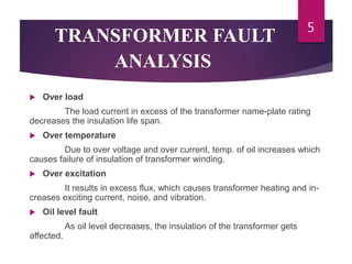
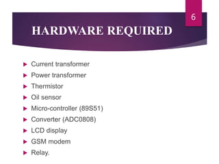
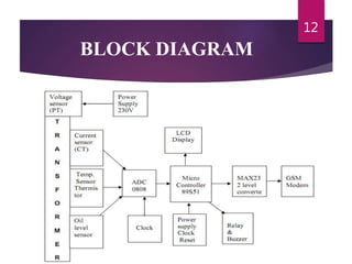

This document describes a GSM-based system for remotely monitoring and detecting faults in distribution transformers. The system uses sensors to monitor the transformer's voltage, temperature, power consumption, and oil level. It sends alerts via GSM if any of these exceed safe limits. A microcontroller processes the sensor data and triggers a relay to disconnect the transformer if a fault is detected, sending an SMS alert. This allows faults to be addressed before complete failure occurs, improving reliability while reducing costs compared to manual monitoring.