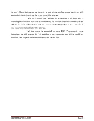
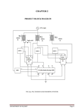
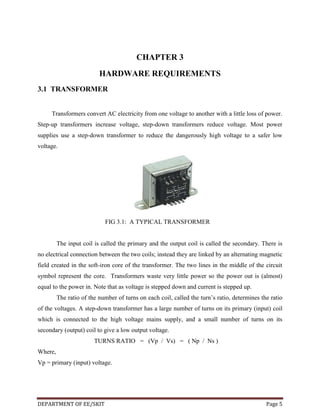
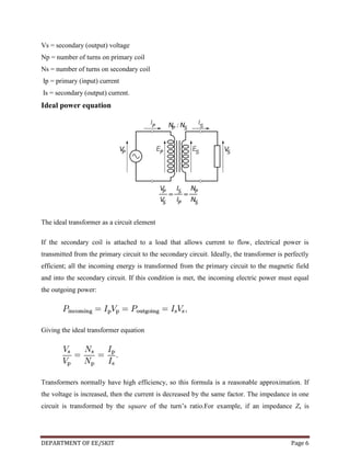
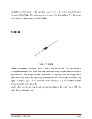
This document provides information about the hardware requirements for a PLC based load sharing project. It discusses transformers, diodes, PLCs, rectifiers, resistors, capacitors, relays, LEDs, and DC motors. Transformers are used to convert AC voltages and connect multiple power sources in parallel. Diodes allow current to flow in one direction. PLCs are used for automation and control. Rectifiers convert AC to DC. Resistors and capacitors are basic electronic components. Relays, LEDs, and DC motors are also used in the circuit. The project aims to automatically share loads between multiple transformers connected to the system based on the load level.
DSTATCOM IS USED IN DISTRIBUTION SYSTEM TO IMPROVE POWER QUALITY LIKE PF CORRECTION,VOLTAGE SAG OR SWELL,HARMONICS ELEMINATION,ETC.VARIOUS CONTROL STRATEGY COMPARISION FOR DSTATCOM.ADVANTAGES AND DISADVANTAGES OF DSTATCOM.APPLICATION OF STASTCOM IN INDIA.
Here my project theme is to monitor and control Transformer health using Arduino, as we all know there are both internal and external faults occur in the transformer, for internal faults we use Buchholz relay and Differential protection relay for external but it is not efficient with time. so,we use Arduino for real time protection, here we fix some values to the Arduino in the program itself according to the rating of the transformer by that we monitor and control whenever the faults occur
Infinite bus bar is one which keeps constant voltage and frequency although the load varies. Thus it may behave like a voltage source with zero internal impedance and infinite rotational inertia.
Power factor improvement is the essence of any power sector for realible operations. This report provides literature study of a fixed capacitor thyristor controlled reactor type of power factor compensator by matlab simulation and implementation in programmed microcontroller. To retaining power factor closed to unity under various load condition the arduino ATmega8 microcontroller is used which is programmed by keil software. The simulation is done using proteus software which display power factor according to the variation in load whenever a capacitive load is connected to the transmission line, a shunt reactor is connected which injects lagging reactive VARs to the power system. This report also includes the matlab simulation for three phase power factor improvement by using fixed capacitor thyristor controlled reactor. As a
result the power factor is improved. The results given in this report provides
suitable matlab simulation and proteus simulation based reactor power compensation and power factor improvement and techniques using a FCTCR.
A transmission line is characterized by four parameters:
series resistance (R) due to conductor resistivity
shunt conductance (G) due to currents along insulator strings and corona; effect is small and usually neglected
series inductance (L) due to magnetic field surrounding the conductor
shunt capacitance (C) due to the electric field between the conductors
These are distributed parameters.
The parameters and hence the characteristics of cables differ significantly from those of overhead lines because the conductors in a cable are
much closer to each other
surrounded by metallic bodies such as shields, lead or aluminum sheets, and steel pipes
separated by insulating material such as impregnated paper, oil, or inert gas
Physical Description
Mathematical Model
Park's "dqo" transportation
Steady-state Analysis
phasor representation in d-q coordinates
link with network equations
Definition of "rotor angle"
Representation of Synchronous Machines in Stability Studies
neglect of stator transients
magnetic saturation
Simplified Models
Synchronous Machine Parameters
Reactive Capability Limits
Consists of two sets of windings:
3 phase armature winding on the stator distributed with centres 120° apart in space
field winding on the rotor supplied by DC
Two basic rotor structures used:
salient or projecting pole structure for hydraulic units (low speed)
round rotor structure for thermal units (high speed)
Salient poles have concentrated field windings; usually also carry damper windings on the pole face.Round rotors have solid steel rotors with distributed windings
Nearly sinusoidal space distribution of flux wave shape obtained by:
distributing stator windings and field windings in many slots (round rotor);
shaping pole faces (salient pole)
LOAD FREQUENCY AND VOLTAGE GENERATION CONTROLPreet_patel
LOAD FREQUENCY AND VOLTAGE GENERATION CONTROL
Load frequency control
Automatic Generation Control
Voltage Control
Primary regulation.
Secondary regulation
real power
Why voltage control is important?
GSM Based Fault Monitoring System (Project)Aishwary Verma
This is a modern technique of Monitoring of switchyard which is used in many other countries.
It will be useful for reducing requirement of manpower.
When a fault occurred a SMS will be sent to the registered mobile number detailing about type of fault and location of fault.
Review Paper on Smart Sensor Network for Air Quality MonitoringAM Publications
Green and clean environment across the globe is very much essential for the health of the nature. Unfortunately different kinds of pollutions are affecting the quality of the environment around us. This review paper is mainly dealing with “Air pollution”, which is a very sensitive issue in developing and developed countries and is directly affecting the human health and disturbs the biological balance of mother earth. Here our aim is to develop a system which will detect maximum air pollutants and which is highly responsive, accurate and low cost and low power consuming.
International Journal of Engineering Research and Applications (IJERA) aims to cover the latest outstanding developments in the field of all Engineering Technologies & science.
International Journal of Engineering Research and Applications (IJERA) is a team of researchers not publication services or private publications running the journals for monetary benefits, we are association of scientists and academia who focus only on supporting authors who want to publish their work. The articles published in our journal can be accessed online, all the articles will be archived for real time access.
Our journal system primarily aims to bring out the research talent and the works done by sciaentists, academia, engineers, practitioners, scholars, post graduate students of engineering and science. This journal aims to cover the scientific research in a broader sense and not publishing a niche area of research facilitating researchers from various verticals to publish their papers. It is also aimed to provide a platform for the researchers to publish in a shorter of time, enabling them to continue further All articles published are freely available to scientific researchers in the Government agencies,educators and the general public. We are taking serious efforts to promote our journal across the globe in various ways, we are sure that our journal will act as a scientific platform for all researchers to publish their works online.
“Microcontroller Based Substation Monitoring system with gsm modem”.Priya Rachakonda
• The system is used for transmitting the message to predefined number about the
status of electrical parameters such as voltage, current, temperature etc., to improve
the quality of power.
• Studied about the protection, monitoring and control of a power system.
The International Journal of Engineering and Science (The IJES)theijes
The International Journal of Engineering & Science is aimed at providing a platform for researchers, engineers, scientists, or educators to publish their original research results, to exchange new ideas, to disseminate information in innovative designs, engineering experiences and technological skills. It is also the Journal's objective to promote engineering and technology education. All papers submitted to the Journal will be blind peer-reviewed. Only original articles will be published.
PROJECT DESCRIPTION
DOWNLOAD
The main objective of this project is to develop a device for wireless power transfer. The concept of wireless power transfer was realized by Nikolas tesla. Wireless power transfer can make a remarkable change in the field of the electrical engineering which eliminates the use conventional copper cables and current carrying wires.
Based on this concept, the project is developed to transfer power within a small range. This project can be used for charging batteries those are physically not possible to be connected electrically such as pace makers (An electronic device that works in place of a defective heart valve) implanted in the body that runs on a battery.
The patient is required to be operated every year to replace the battery. This project is designed to charge a rechargeable battery wirelessly for the purpose. Since charging of the battery is not possible to be demonstrated, we are providing a DC fan that runs through wireless power.
This project is built upon using an electronic circuit which converts AC 230V 50Hz to AC 12V, High frequency. The output is fed to a tuned coil forming as primary of an air core transformer. The secondary coil develops a voltage of HF 12volt.
Thus the transfer of power is done by the primary(transmitter) to the secondary that is separated with a considerable distance(say 3cm). Therefore the transfer could be seen as the primary transmits and the secondary receives the power to run load.
Moreover this technique can be used in number of applications, like to charge a mobile phone, iPod, laptop battery, propeller clock wirelessly. And also this kind of charging provides a far lower risk of electrical shock as it would be galvanically isolated.
Electrical Discharge Machining Flyback Converter using UC3842 Current Mode PW...IJPEDS-IAES
This paper presents a current mode Pulse Width Modulation (PWM) controlled Flyback converter using UC3842 for Electrical Discharge Machining current generator control circuit. Circuit simplicity and high efficiency can be achieved by a Flyback converter with current mode PWM controller. The behaviors of the system's operation is analyzed and discussed by varying the load resistance. Matlab sofware is used to simulate the Flyback converter where a prototype has been built and tested to verify its performance.
This paper presents the simulation design of dc/dc interleaved boost converter with zero-voltage switching (ZVS). By employin the interleaved structure, the input current stresses to switching devices were reduced and this signified to a switching conduction loss reduction. All the parameters had been calculated theoretically. The proposed converter circuit was simulated by using MATLAB/Simulink and PSpice software programmes. The converter circuit model, with specifications of output power of 200 W, input voltage range from 10~60 V, and operates at 100 kHz switching frequency was simulated to validate the designed parameters. The results showed that the main switches of the model converter circuit achieved ZVS conditions during the interleaving operation. Consequently, the switching losses in the main switching devices were reduced. Thus, the proposed converter circuit model offers advantages of input current stress and switching loss reductions. Hence, based on the designed parameters and results, the converter model can be extended for hardware implementation.
International Journal of Engineering Research and Applications (IJERA) is an open access online peer reviewed international journal that publishes research and review articles in the fields of Computer Science, Neural Networks, Electrical Engineering, Software Engineering, Information Technology, Mechanical Engineering, Chemical Engineering, Plastic Engineering, Food Technology, Textile Engineering, Nano Technology & science, Power Electronics, Electronics & Communication Engineering, Computational mathematics, Image processing, Civil Engineering, Structural Engineering, Environmental Engineering, VLSI Testing & Low Power VLSI Design etc.
International Journal of Engineering Research and DevelopmentIJERD Editor
Electrical, Electronics and Computer Engineering,
Information Engineering and Technology,
Mechanical, Industrial and Manufacturing Engineering,
Automation and Mechatronics Engineering,
Material and Chemical Engineering,
Civil and Architecture Engineering,
Biotechnology and Bio Engineering,
Environmental Engineering,
Petroleum and Mining Engineering,
Marine and Agriculture engineering,
Aerospace Engineering.
Speed Control Of Separately Excited Dc Motor Using A High Efficiency Flyback ...IJERA Editor
This paper deals with Speed control of separately excited DC motor using flyback converter with a new non complementary active clamp control method to achieve soft switching and high efficiency for heavy motor load and light load conditions. This is quite attractive for low power application with universal ac inputs, such as external adaptors. With the proposed control technique, the energy in the leakage inductance can be fully recycled. The soft switching can be achieved for the main switch and the absorbed leakage energy is transferred to the output and input side. In the Proposed model the resistive and DC motor is connected to flyback converter and it is simulated with different nominal voltages and rated speed is controlled at different levels for the N-type active clamp flyback converter and P-type active clamp flyback converter respectively. N-type active clamp flyback converter is suitable for high speed variation applications and P-type active clamp flyback converter is suitable for low speed variation applications.
The world of search engine optimization (SEO) is buzzing with discussions after Google confirmed that around 2,500 leaked internal documents related to its Search feature are indeed authentic. The revelation has sparked significant concerns within the SEO community. The leaked documents were initially reported by SEO experts Rand Fishkin and Mike King, igniting widespread analysis and discourse. For More Info:- https://news.arihantwebtech.com/search-disrupted-googles-leaked-documents-rock-the-seo-world/
Affordable Stationery Printing Services in Jaipur | Navpack n PrintNavpack & Print
Looking for professional printing services in Jaipur? Navpack n Print offers high-quality and affordable stationery printing for all your business needs. Stand out with custom stationery designs and fast turnaround times. Contact us today for a quote!
What is the TDS Return Filing Due Date for FY 2024-25.pdfseoforlegalpillers
It is crucial for the taxpayers to understand about the TDS Return Filing Due Date, so that they can fulfill your TDS obligations efficiently. Taxpayers can avoid penalties by sticking to the deadlines and by accurate filing of TDS. Timely filing of TDS will make sure about the availability of tax credits. You can also seek the professional guidance of experts like Legal Pillers for timely filing of the TDS Return.
RMD24 | Retail media: hoe zet je dit in als je geen AH of Unilever bent? Heid...BBPMedia1
Grote partijen zijn al een tijdje onderweg met retail media. Ondertussen worden in dit domein ook de kansen zichtbaar voor andere spelers in de markt. Maar met die kansen ontstaan ook vragen: Zelf retail media worden of erop adverteren? In welke fase van de funnel past het en hoe integreer je het in een mediaplan? Wat is nu precies het verschil met marketplaces en Programmatic ads? In dit half uur beslechten we de dilemma's en krijg je antwoorden op wanneer het voor jou tijd is om de volgende stap te zetten.
Skye Residences | Extended Stay Residences Near Toronto Airportmarketingjdass
Experience unparalleled EXTENDED STAY and comfort at Skye Residences located just minutes from Toronto Airport. Discover sophisticated accommodations tailored for discerning travelers.
Website Link :
https://skyeresidences.com/
https://skyeresidences.com/about-us/
https://skyeresidences.com/gallery/
https://skyeresidences.com/rooms/
https://skyeresidences.com/near-by-attractions/
https://skyeresidences.com/commute/
https://skyeresidences.com/contact/
https://skyeresidences.com/queen-suite-with-sofa-bed/
https://skyeresidences.com/queen-suite-with-sofa-bed-and-balcony/
https://skyeresidences.com/queen-suite-with-sofa-bed-accessible/
https://skyeresidences.com/2-bedroom-deluxe-queen-suite-with-sofa-bed/
https://skyeresidences.com/2-bedroom-deluxe-king-queen-suite-with-sofa-bed/
https://skyeresidences.com/2-bedroom-deluxe-queen-suite-with-sofa-bed-accessible/
#Skye Residences Etobicoke, #Skye Residences Near Toronto Airport, #Skye Residences Toronto, #Skye Hotel Toronto, #Skye Hotel Near Toronto Airport, #Hotel Near Toronto Airport, #Near Toronto Airport Accommodation, #Suites Near Toronto Airport, #Etobicoke Suites Near Airport, #Hotel Near Toronto Pearson International Airport, #Toronto Airport Suite Rentals, #Pearson Airport Hotel Suites
Enterprise Excellence is Inclusive Excellence.pdfKaiNexus
Enterprise excellence and inclusive excellence are closely linked, and real-world challenges have shown that both are essential to the success of any organization. To achieve enterprise excellence, organizations must focus on improving their operations and processes while creating an inclusive environment that engages everyone. In this interactive session, the facilitator will highlight commonly established business practices and how they limit our ability to engage everyone every day. More importantly, though, participants will likely gain increased awareness of what we can do differently to maximize enterprise excellence through deliberate inclusion.
What is Enterprise Excellence?
Enterprise Excellence is a holistic approach that's aimed at achieving world-class performance across all aspects of the organization.
What might I learn?
A way to engage all in creating Inclusive Excellence. Lessons from the US military and their parallels to the story of Harry Potter. How belt systems and CI teams can destroy inclusive practices. How leadership language invites people to the party. There are three things leaders can do to engage everyone every day: maximizing psychological safety to create environments where folks learn, contribute, and challenge the status quo.
Who might benefit? Anyone and everyone leading folks from the shop floor to top floor.
Dr. William Harvey is a seasoned Operations Leader with extensive experience in chemical processing, manufacturing, and operations management. At Michelman, he currently oversees multiple sites, leading teams in strategic planning and coaching/practicing continuous improvement. William is set to start his eighth year of teaching at the University of Cincinnati where he teaches marketing, finance, and management. William holds various certifications in change management, quality, leadership, operational excellence, team building, and DiSC, among others.
Discover the innovative and creative projects that highlight my journey throu...dylandmeas
Discover the innovative and creative projects that highlight my journey through Full Sail University. Below, you’ll find a collection of my work showcasing my skills and expertise in digital marketing, event planning, and media production.
Falcon stands out as a top-tier P2P Invoice Discounting platform in India, bridging esteemed blue-chip companies and eager investors. Our goal is to transform the investment landscape in India by establishing a comprehensive destination for borrowers and investors with diverse profiles and needs, all while minimizing risk. What sets Falcon apart is the elimination of intermediaries such as commercial banks and depository institutions, allowing investors to enjoy higher yields.
Premium MEAN Stack Development Solutions for Modern BusinessesSynapseIndia
Stay ahead of the curve with our premium MEAN Stack Development Solutions. Our expert developers utilize MongoDB, Express.js, AngularJS, and Node.js to create modern and responsive web applications. Trust us for cutting-edge solutions that drive your business growth and success.
Know more: https://www.synapseindia.com/technology/mean-stack-development-company.html
Cracking the Workplace Discipline Code Main.pptxWorkforce Group
Cultivating and maintaining discipline within teams is a critical differentiator for successful organisations.
Forward-thinking leaders and business managers understand the impact that discipline has on organisational success. A disciplined workforce operates with clarity, focus, and a shared understanding of expectations, ultimately driving better results, optimising productivity, and facilitating seamless collaboration.
Although discipline is not a one-size-fits-all approach, it can help create a work environment that encourages personal growth and accountability rather than solely relying on punitive measures.
In this deck, you will learn the significance of workplace discipline for organisational success. You’ll also learn
• Four (4) workplace discipline methods you should consider
• The best and most practical approach to implementing workplace discipline.
• Three (3) key tips to maintain a disciplined workplace.
RMD24 | Debunking the non-endemic revenue myth Marvin Vacquier Droop | First ...BBPMedia1
Marvin neemt je in deze presentatie mee in de voordelen van non-endemic advertising op retail media netwerken. Hij brengt ook de uitdagingen in beeld die de markt op dit moment heeft op het gebied van retail media voor niet-leveranciers.
Retail media wordt gezien als het nieuwe advertising-medium en ook mediabureaus richten massaal retail media-afdelingen op. Merken die niet in de betreffende winkel liggen staan ook nog niet in de rij om op de retail media netwerken te adverteren. Marvin belicht de uitdagingen die er zijn om echt aansluiting te vinden op die markt van non-endemic advertising.
Business Valuation Principles for EntrepreneursBen Wann
This insightful presentation is designed to equip entrepreneurs with the essential knowledge and tools needed to accurately value their businesses. Understanding business valuation is crucial for making informed decisions, whether you're seeking investment, planning to sell, or simply want to gauge your company's worth.
Pitch Deck Teardown: RAW Dating App's $3M Angel deck
project report on plc based load sharing
1. CONTENTS
CERTIFICATE
i
ACKNOWLEDGEMENT
ii
ABSTRACT
iii
Ch. No
CHAPTER NAME
PAGE NO
1
INTRODUCTION TO PLC BASED LOAD SHARING
2-3
2
BLOCK DIAGRAM OF PROJECT
4
3.
HARDWARE
REQUIREMENTS
5
3.1 TRANSFORMERS
5-7
3.2 DIODES
7
3.3 PROGRAMMABLE LOGIC CONTROLER
8
(ALLEN BRADLEY MICROLOGIX 1000)
3.4 RECTIFIER
8-9
3.5 RESISTOR
9-12
3.6 CAPACITOR
13-16
3.7 RELAY
17
3.8 LED/DC INDICATOR17-20
3.9DC MOTOR (12V 300RPM)
CONCLUSION
21-22
23
REFERENCE
DEPARTMENT OF EE, SKIT
24
2. LIST OF FIGURE
FIG. No
2(a)
FIGURE NAME
PAGE NO
PLC BASED LOAD SHARING SYSTEM
4
3.1 A TYPICAL TRANSFORMER
5
3.2
A DIODE
7
3.3
A TYPICAL PLC
8
3.4CIRCUIT DIAGRAM AND WAVEFORM FOR BRIDGE RECTIFIER
9
3.5
VARIOUS TYPES OF RESISTOR
3.6(a)
VARIOUS TYPES OF CAPACITOR
13
3.6(b)
PARALLEL PLATE CAPACITOR
15
3.7(a)
A TYPICAL 8 PIN RELAY
17
3.8(a)
TYPICAL LED
18
3.8(b)
CIRCUIT SYMBOL OF LED
18
3.8(c)
DIFFERENT TYPES OF LED
19
3.9
A 12V 300 RPM DC MOTOR
21
DEPARTMENT OF EE/SKIT
10
Page 1
3. CHAPTER 1
INTRODUCTION TO PLC BASED LOAD SHARING
A Programmable Logic Controller, PLC or Programmable Controller is a digital computer used
forautomation of electromechanical processes, such as control of machinery on factory assembly
lines,amusement rides, or light fixtures. PLCs are used in many industries and machines. Unlike
general-purpose computers, the PLC is designed for multiple inputs and output arrangements,
extended temperature ranges, immunity to electrical noise, and resistance to vibration and
impact. Programs to control machine operation are typically stored in battery-backed-up or nonvolatile memory. A PLC is an example of a hard real timesystem since output results must be
produced in response to input conditions within a limited time, otherwise unintended operation
will result.
For supplying a load in excess of the rating of an existing transformer, two or more transformers
may be connected in parallel with the existing transformer. The transformers are connected in
parallel when load on one of the transformers is more than its capacity. The reliability is
increased with parallel operation than to have single larger unit. The cost associated with
maintaining the spares is less when two transformers are connected in parallel.
It is usually economical to install another transformer in parallel instead of replacing the existing
transformer by a single larger unit. The cost of a spare unit in the case of two parallel
transformers (of equal rating) is also lower than that of a single large transformer. In addition, it
is preferable to have a parallel transformer for the reason of reliability. With this at least half the
load can be supplied with one transformer out of service.
In this project we are designing a system which is capable of sharing loads among several
installed sources. It means according to increased loads it automatically adds new sources of
power and in case of decrement in loads sources will automatically cut out.
There are three transformers working as sources in this project. At very
first time 1st transformer is under working condition and it will be remain as it is till it continues
DEPARTMENT OF EE/SKIT
Page 2
4. its supply. If any faults occurs and its supply to load is interrupted the second transformer will
automatically come in role and the former one will be removed.
Now take another case consider 1st transformer is in work and if
increasing loads becomes more than its rated capacity the 2nd transformer will automatically be
added in the circuit and for further loads next sources will be added and so on. And vice versa if
load is decreased transformer will be removed.
All this system is automated by using PLC (Programmable Logic
Controller). We will program the PLC according to our requirement that will be capable of
automatic switching of transformer circuits and will operate them.
DEPARTMENT OF EE/SKIT
Page 3
5. CHAPTER 2
PROJECT BLOCK DIAGRAM
FIG 2(a): PLC BASED LOAD SHARING SYSTEM
DEPARTMENT OF EE/SKIT
Page 4
6. CHAPTER 3
HARDWARE REQUIREMENTS
3.1 TRANSFORMER
Transformers convert AC electricity from one voltage to another with a little loss of power.
Step-up transformers increase voltage, step-down transformers reduce voltage. Most power
supplies use a step-down transformer to reduce the dangerously high voltage to a safer low
voltage.
FIG 3.1: A TYPICAL TRANSFORMER
The input coil is called the primary and the output coil is called the secondary. There is
no electrical connection between the two coils; instead they are linked by an alternating magnetic
field created in the soft-iron core of the transformer. The two lines in the middle of the circuit
symbol represent the core. Transformers waste very little power so the power out is (almost)
equal to the power in. Note that as voltage is stepped down and current is stepped up.
The ratio of the number of turns on each coil, called the turn’s ratio, determines the ratio
of the voltages. A step-down transformer has a large number of turns on its primary (input) coil
which is connected to the high voltage mains supply, and a small number of turns on its
secondary (output) coil to give a low output voltage.
TURNS RATIO = (Vp / Vs) = ( Np / Ns )
Where,
Vp = primary (input) voltage.
DEPARTMENT OF EE/SKIT
Page 5
7. Vs = secondary (output) voltage
Np = number of turns on primary coil
Ns = number of turns on secondary coil
Ip = primary (input) current
Is = secondary (output) current.
Ideal power equation
The ideal transformer as a circuit element
If the secondary coil is attached to a load that allows current to flow, electrical power is
transmitted from the primary circuit to the secondary circuit. Ideally, the transformer is perfectly
efficient; all the incoming energy is transformed from the primary circuit to the magnetic field
and into the secondary circuit. If this condition is met, the incoming electric power must equal
the outgoing power:
Giving the ideal transformer equation
Transformers normally have high efficiency, so this formula is a reasonable approximation. If
the voltage is increased, then the current is decreased by the same factor. The impedance in one
circuit is transformed by the square of the turn’s ratio.For example, if an impedance Zs is
DEPARTMENT OF EE/SKIT
Page 6
8. attached across the terminals of the secondary coil, it appears to the primary circuit to have an
impedance of (Np/Ns)2Zs. This relationship is reciprocal, so that the impedance Zp of the primary
circuit appears to the secondary to be (Ns/Np)2Zp.
3.2DIODE
FIG 3.2: A DIODE
Diodes are components that allow current to flow in only one direction. They have a positive
side (leg) and a negative side. When the voltage on the positive leg is higher than on the negative
leg then current flows through the diode (the resistance is very low). When the voltage is lower
on the positive leg than on the negative leg then the current does not flow (the resistance is very
high). The negative leg of a diode is the one with the line closest to it. It is called the cathode.
The positive end is called the anode.
Usually when current is flowing through a diode, the voltage on the positive leg is 0.65 volts
higher than on the negative leg.
DEPARTMENT OF EE/SKIT
Page 7
9. 3.3 PROGRAMMABLE LOGIC CONTROLLER
FIG 3.3: A TYPICAL PLC
A Programmable Logic Controller, PLC or Programmable Controller is a digital computer used
for automation of electromechanical processes, such as control of machinery on factory assembly
lines, amusement rides, or light fixtures. PLCs are used in many industries and machines. Unlike
general-purpose computers, the PLC is designed for multiple inputs and output arrangements,
extended temperature ranges, immunity to electrical noise, and resistance to vibration and
impact. Programs to control machine operation are typically stored in battery-backed-up or nonvolatile memory. A PLC is an example of a hard real time system since output results must be
produced in response to input conditions within a limited time, otherwise unintended operation
will result.
3.4RECTIFIER
A rectifier is an electrical device that converts alternating current (AC), which
periodically reverses direction, to direct current (DC), current that flows in only one direction, a
process known as rectification. Rectifiers have many uses including as components of power
supplies and as detectors of radio signals. Rectifiers may be made of solid statediodes, vacuum
DEPARTMENT OF EE/SKIT
Page 8
10. tube diodes, mercury arc valves, and other components. The output from the transformer is fed to
the rectifier. It converts A.C. into pulsating D.C. The rectifier may be a half wave or a full wave
rectifier. In this project, a bridge rectifier is used because of its merits like good stability and full
wave rectification. In positive half cycleonly two diodes( 1 set of parallel diodes) will conduct, in
negative half cycle remaining two diodes will conduct and they will conduct only in forward bias
only.
FIG3.4: CIRCUIT DIAGRAM AND WAVEFORM FOR BRIDGE RECTIFIER
3.5 RESISTOR
A resistor is a two-terminal electronic component designed to oppose an electric current by
producing a voltage drop between its terminals in proportion to the current, that is, in accordance
with Ohm's law:
V = IR
Resistors are used as part of electrical networks and electronic circuits. They are extremely
commonplace in most electronic equipment. Practical resistors can be made of various
DEPARTMENT OF EE/SKIT
Page 9
11. compounds and films, as well as resistance wire (wire made of a high-resistivity alloy, such as
nickel/chrome).
The primary characteristics of resistors are their resistance and the power they can
dissipate. Other characteristics include temperature coefficient, noise, and inductance. Less wellknown is critical resistance, the value below which power dissipation limits the maximum
permitted current flow, and above which the limit is applied voltage. Critical resistance depends
upon the materials constituting the resistor as well as its physical dimensions; it's determined by
design.
Resistors can be integrated into hybrid and printed circuits, as well as integrated
circuits. Size, and position of leads (or terminals) are relevant to equipment designers; resistors
must be physically large enough not to overheat when dissipating their power.
FIG 3.5: VARIOUS TYPES OF RESISTOR
A resistor is a two-terminalpassiveelectronic component which implements electrical
resistance as a circuit element. When a voltage V is applied across the terminals of a resistor, a
current I will flow through the resistor in direct proportion to that voltage. The reciprocal of the
constant of proportionality is known as the resistance R, since, with a given voltage V, a larger
value of R further "resists" the flow of current I as given by Ohm's law:
DEPARTMENT OF EE/SKIT
Page 10
12. Resistors are common elements of electrical networks and electronic circuits and are
ubiquitous in most electronic equipment. Practical resistors can be made of various compounds
and films, as well as resistance wire (wire made of a high-resistivity alloy, such as nickelchrome). Resistors are also implemented within integrated circuits, particularly analog devices,
and can also be integrated into hybrid and printed circuits.
The electrical functionality of a resistor is specified by its resistance: common
commercial resistors are manufactured over a range of more than 9 orders of magnitude. When
specifying that resistance in an electronic design, the required precision of the resistance may
require attention to the manufacturing tolerance of the chosen resistor, according to its specific
application. The temperature coefficient of the resistance may also be of concern in some
precision applications. Practical resistors are also specified as having a maximum power rating
which must exceed the anticipated power dissipation of that resistor in a particular circuit: this is
mainly of concern in power electronics applications. Resistors with higher power ratings are
physically larger and may require heat sinking. In a high voltage circuit, attention must
sometimes be paid to the rated maximum working voltage of the resistor.
The series inductance of a practical resistor causes its behavior to depart from ohms law;
this specification can be important in some high-frequency applications for smaller values of
resistance. In a low-noise amplifier or pre-amp the noise characteristics of a resistor may be an
issue. The unwanted inductance, excess noise, and temperature coefficient are mainly dependent
on the technology used in manufacturing the resistor. They are not normally specified
individually for a particular family of resistors manufactured using a particular technology. A
family of discrete resistors is also characterized according to its form factor, that is, the size of
the device and position of its leads (or terminals) which is relevant in the practical manufacturing
of circuits using them.
Units
The ohm (symbol: Ω) is the SI unit of electrical resistance, named after Georg Simon
Ohm. An ohm is equivalent to a volt per ampere. Since resistors are specified and manufactured
DEPARTMENT OF EE/SKIT
Page 11
13. over a very large range of values, the derived units of milliohm (1 mΩ = 10−3 Ω), kilohm (1 kΩ =
103 Ω), and megohm (1 MΩ = 106 Ω) are also in common usage.
The reciprocal of resistance R is called conductance G = 1/R and is measured in Siemens
(SI unit), sometimes referred to as a mho. Thus a Siemens is the reciprocal of an ohm: S = Ω − 1.
Although the concept of conductance is often used in circuit analysis, practical resistors are
always specified in terms of their resistance (ohms) rather than conductance.
Variable resistors
Adjustable resistors
A resistor may have one or more fixed tapping points so that the resistance can be
changed by moving the connecting wires to different terminals. Some wirewound power resistors
have a tapping point that can slide along the resistance element, allowing a larger or smaller part
of the resistance to be used.
Where continuous adjustment of the resistance value during operation of equipment is
required, the sliding resistance tap can be connected to a knob accessible to an operator. Such a
device is called a rheostat and has two terminals.
Potentiometers
A common element in electronic devices is a three-terminal resistor with a continuously
adjustable tapping point controlled by rotation of a shaft or knob. These variable resistors are
known as potentiometers when all three terminals are present, since they act as a continuously
adjustable voltage divider. A common example is a volume control for a radio receiver.
Accurate, high-resolution panel-mounted potentiometers (or "pots") have resistance
elements typically wire wound on a helical mandrel, although some include a conductive-plastic
resistance coating over the wire to improve resolution. These typically offer ten turns of their
shafts to cover their full range. They are usually set with dials that include a simple turns counter
and a graduated dial. Electronic analog computers used them in quantity for setting coefficients,
and delayed-sweep oscilloscopes of recent decades included one on their panels.
DEPARTMENT OF EE/SKIT
Page 12
14. 3.6 CAPACITOR
A capacitor or condenser is a passive electronic component consisting of a pair of conductors
separated by a dielectric. When a voltage potential difference exists between the conductors, an
electric field is present in the dielectric. This field stores energy and produces a mechanical force
between the plates. The effect is greatest between wide, flat, parallel, narrowly separated
conductors.
An ideal capacitor is characterized by a single constant value, capacitance, which is
measured in farads. This is the ratio of the electric charge on each conductor to the potential
difference between them. In practice, the dielectric between the plates passes a small amount of
leakage current. The conductors and leads introduce an equivalent series resistance and the
dielectric has an electric field strength limit resulting in a breakdown voltage.
The properties of capacitors in a circuit may determine the resonant frequency and
quality factor of a resonant circuit, power dissipation and operating frequency in a digital logic
circuit, energy capacity in a high-power system, and many other important aspects.
FIG 3.6(a): VARIOUS TYPES OF CAPACITORS
DEPARTMENT OF EE/SKIT
Page 13
15. A capacitor (formerly known as condenser) is a device for storing electric charge. The
forms of practical capacitors vary widely, but all contain at least two conductors separated by a
non-conductor. Capacitors used as parts of electrical systems, for example, consist of metal foils
separated by a layer of insulating film.
Capacitors are widely used in electronic circuits for blocking direct current while
allowing alternating current to pass, in filter networks, for smoothing the output of power
supplies, in the resonant circuits that tune radios to particular frequencies and for many other
purposes.
A capacitor is a passiveelectronic component consisting of a pair of conductors separated
by a dielectric (insulator). When there is a potential difference (voltage) across the conductors, a
static electric field develops in the dielectric that stores energy and produces a mechanical force
between the conductors. An ideal capacitor is characterized by a single constant value,
capacitance, measured in farads. This is the ratio of the electric charge on each conductor to the
potential difference between them.
The capacitance is greatest when there is a narrow separation between large areas of
conductor, hence capacitor conductors are often called "plates", referring to an early means of
construction. In practice the dielectric between the plates passes a small amount of leakage
current and also has an electric field strength limit, resulting in a breakdown voltage, while the
conductors and leads introduce an undesired inductance and resistance.
Theory of operation
Capacitance
DEPARTMENT OF EE/SKIT
Page 14
16. Charge separation in a parallel-plate capacitor causes an internal electric field. A dielectric
(orange) reduces the field and increases the capacitance.
FIG 3.6(b): PARALLEL PLATE CAPACITOR
A simple demonstration of a parallel-plate capacitor
A capacitor consists of two conductors separated by a non-conductive region. The nonconductive region is called the dielectric or sometimes the dielectric medium. In simpler terms,
the dielectric is just an electrical insulator. Examples of dielectric mediums are glass, air, paper,
vacuum, and even a semiconductordepletion region chemically identical to the conductors. A
capacitor is assumed to be self-contained and isolated, with no net electric charge and no
influence from any external electric field. The conductors thus hold equal and opposite charges
on their facing surfaces, and the dielectric develops an electric field. In SI units, a capacitance of
one farad means that one coulomb of charge on each conductor causes a voltage of one volt
across the device.
The capacitor is a reasonably general model for electric fields within electric circuits. An ideal
capacitor is wholly characterized by a constant capacitance C, defined as the ratio of charge ±Q
on each conductor to the voltage V between them:
Sometimes charge build-up affects the capacitor mechanically, causing its capacitance to vary. In
this case, capacitance is defined in terms of incremental changes:
DEPARTMENT OF EE/SKIT
Page 15
17. Energy storage
Work must be done by an external influence to "move" charge between the conductors in a
capacitor. When the external influence is removed the charge separation persists in the electric
field and energy is stored to be released when the charge is allowed to return to its equilibrium
position. The work done in establishing the electric field, and hence the amount of energy stored,
is given by:
Current-voltage relation
The current i(t) through any component in an electric circuit is defined as the rate of flow of a
charge q(t) passing through it, but actual charges, electrons, cannot pass through the dielectric
layer of a capacitor, rather an electron accumulates on the negative plate for each one that leaves
the positive plate, resulting in an electron depletion and consequent positive charge on one
electrode that is equal and opposite to the accumulated negative charge on the other. Thus the
charge on the electrodes is equal to the integral of the current as well as proportional to the
voltage as discussed above. As with any antiderivative, a constant of integration is added to
represent the initial voltage v (t0). This is the integral form of the capacitor equation,
.
Taking the derivative of this, and multiplying by C, yields the derivative form,
.
The dual of the capacitor is the inductor, which stores energy in the magnetic field rather than the
electric field. Its current-voltage relation is obtained by exchanging current and voltage in the
capacitor equations and replacing C with the inductance L.
DEPARTMENT OF EE/SKIT
Page 16
18. 3.7 RELAY
FIG 3.7: A TYPICAL 8 PIN RELAY
A relay is an electrically operated switch. Many relays use an electromagnet to operate a
switching mechanism mechanically, but other operating principles are also used. Relays are used
where it is necessary to control a circuit by a low-power signal (with complete electrical isolation
between control and controlled circuits), or where several circuits must be controlled by one
signal. The first relays were used in long distance telegraph circuits, repeating the signal coming
in from one circuit and re-transmitting it to another. Relays were used extensively in telephone
exchanges and early computers to perform logical operations.
A type of relay that can handle the high power required to directly control an electric motor or
other loads is called a contactor. Solid-state relays control power circuits with no moving parts,
instead using a semiconductor device to perform switching. Relays with calibrated operating
characteristics and sometimes multiple operating coils are used to protect electrical circuits from
overload or faults; in modern electric power systems these functions are performed by digital
instruments still called "protective relays".
3.8 LED
LEDs are semiconductor devices. Like transistors, and other diodes, LEDs are made out of
silicon. What makes an LED give off light are the small amounts of chemical impurities that are
added to the silicon, such as gallium, arsenide, indium, and nitride.
DEPARTMENT OF EE/SKIT
Page 17
19. When current passes through the LED, it emits photons as a byproduct. Normal light
bulbs produce light by heating a metal filament until it is white hot. LEDs produce photons
directly and not via heat, they are far more efficient than incandescent bulbs.
FIG 3.8(a): TYPICAL LED
FIG 3.8(b): CIRCUIT SYMBOL OF LED
Not long ago LEDs were only bright enough to be used as indicators on dashboards or
electronic equipment. But recent advances have made LEDs bright enough to rival traditional
lighting technologies. Modern LEDs can replace incandescent bulbs in almost any application.
Types of LED’S
LEDs are produced in an array of shapes and sizes. The 5 mm cylindrical package is the most
common, estimated at 80% of world production. The color of the plastic lens is often the same as the
actual color of light emitted, but not always. For instance, purple plastic is often used for infrared
LEDs, and most blue devices have clear housings. There are also LEDs in extremely tiny packages,
such as those found on blinkers and on cell phone keypads. The main types of LEDs are miniature,
high power devices and custom designs such as alphanumeric or multi-color.
DEPARTMENT OF EE/SKIT
Page 18
20. Fig 3.8(c) DIFFERENT TYPES OF LED’S
Colors and materials of LED’S
Conventional LED’S are made from a variety of inorganic semiconductor materials, the
following table shows the available colours with wavelength range, voltage drop and material.
White LED’S
Light Emitting Diodes (LED) have recently become available that are white and bright,
so bright that they seriously compete with incandescent lamps in lighting applications. They are
still pretty expensive as compared to a GOW lamp but draw much less current and project a
fairly well focused beam.
The diode in the photo came with a neat little reflector that tends to sharpen the beam a
little but doesn't seem to add much to the overall intensity.
When run within their ratings, they are more reliable than lamps as well. Red LEDs are
now being used in automotive and truck tail lights and in red traffic signal lights. You will be
DEPARTMENT OF EE/SKIT
Page 19
21. able to detect them because they look like an array of point sources and they go on and off
instantly as compared to conventional incandescent lamps.
LEDs are monochromatic (one color) devices. The color is determined by the band gap of
the semiconductor used to make them. Red, green, yellow and blue LEDs are fairly common.
White light contains all colors and cannot be directly created by a single LED. The most
common form of "white" LED really isn't white. It is a Gallium Nitride blue LED coated with a
phosphor that, when excited by the blue LED light, emits a broad range spectrum that in addition
to the blue emission, makes a fairly white light.
There is a claim that these white LED's have a limited life. After 1000 hours or so of
operation, they tend to yellow and dim to some extent. Running the LEDs at more than their
rated current will certainly accelerate this process.
There are two primary ways of producing high intensity white-light using LED’S. One is
to use individual LED’S that emit three primary colours—red, green, and blue—and then mix all
the colours to form white light. The other is to use a phosphor material to convert
monochromatic light from a blue or UV LED to broad-spectrum white light, much in the same
DEPARTMENT OF EE/SKIT
Page 20
22. way a fluorescent light bulb works. Due to metamerism, it is possible to have quite different
spectra that appear white
3.9 DC MOTOR
FIG 3.9: A 12V 300RPM DC MOTOR
A DC motor is a mechanically commutated electric motor powered from direct current (DC).
The stator is stationary in space by definition and therefore the current in the rotor is switched by
the commutator to also be stationary in space. This is how the relative angle between the stator
and rotor magnetic flux is maintained near 90 degrees, which generates the maximum torque.
DC motors have a rotating armature winding (winding in which a voltage is induced) but nonrotating armature magnetic field and a static field winding (winding that produce the main
magnetic flux) or permanent magnet. Different connections of the field and armature winding
provide different inherent speed/torque regulation characteristics. The speed of a DC motor can
DEPARTMENT OF EE/SKIT
Page 21
23. be controlled by changing the voltage applied to the armature or by changing the field current.
The introduction of variable resistance in the armature circuit or field circuit allowed speed
control. Modern DC motors are often controlled by power electronics systems called DC drives.
The introduction of DC motors to run machinery eliminated the need for local steam or internal
combustion engines, and line shaft drive systems. DC motors can operate directly from
rechargeable batteries, providing the motive power for the first electric vehicles. Today DC
motors are still found in applications as small as toys and disk drives, or in large sizes to operate
steel rolling mills and paper machines.
DEPARTMENT OF EE/SKIT
Page 22
24. CONCLUSION
This report is prepared on the basis of study of theproject PLC BASED LOAD
SHARING. For supplying a load in excess of the rating of an existing transformer,
two or more transformers may be connected in parallel with the existing
transformer. The transformers are connected in parallel when load on one of the
transformers is more than its capacity. The entire process can be controlled using a
programmable logic controller i.e a PLC. The reliability is increased with parallel
operation than to have single larger unit also the cost associated with maintaining
the spares is less when two transformers are connected in parallel.
The most important aspect during ourproject was to study the sharing of load
between transformers,During this time I was able to relate the theoretical part to
the practical. This project as a whole proved to be extremely informative and
experience building and things learnt would help a lot in snapping the future ahead
a better way.
DEPARTMENT OF EE/SKIT
Page 23
25. REFERENCE
TEXT BOOKS REFERED:
1. “Electrical power system ” by Ashfaq Husain, CVS Publications.
2. “Modern Power System Analysis”by D P Kothari and I G Nagrath,
Mc Graw Hill Education
WEBSITES
www.britannica.com
www.beyondlogic.org
www.wikipedia.org
www.howstuffworks.com
www.alldatasheets.com
DEPARTMENT OF EE/SKIT
Page 24