Downloaded 1,238 times
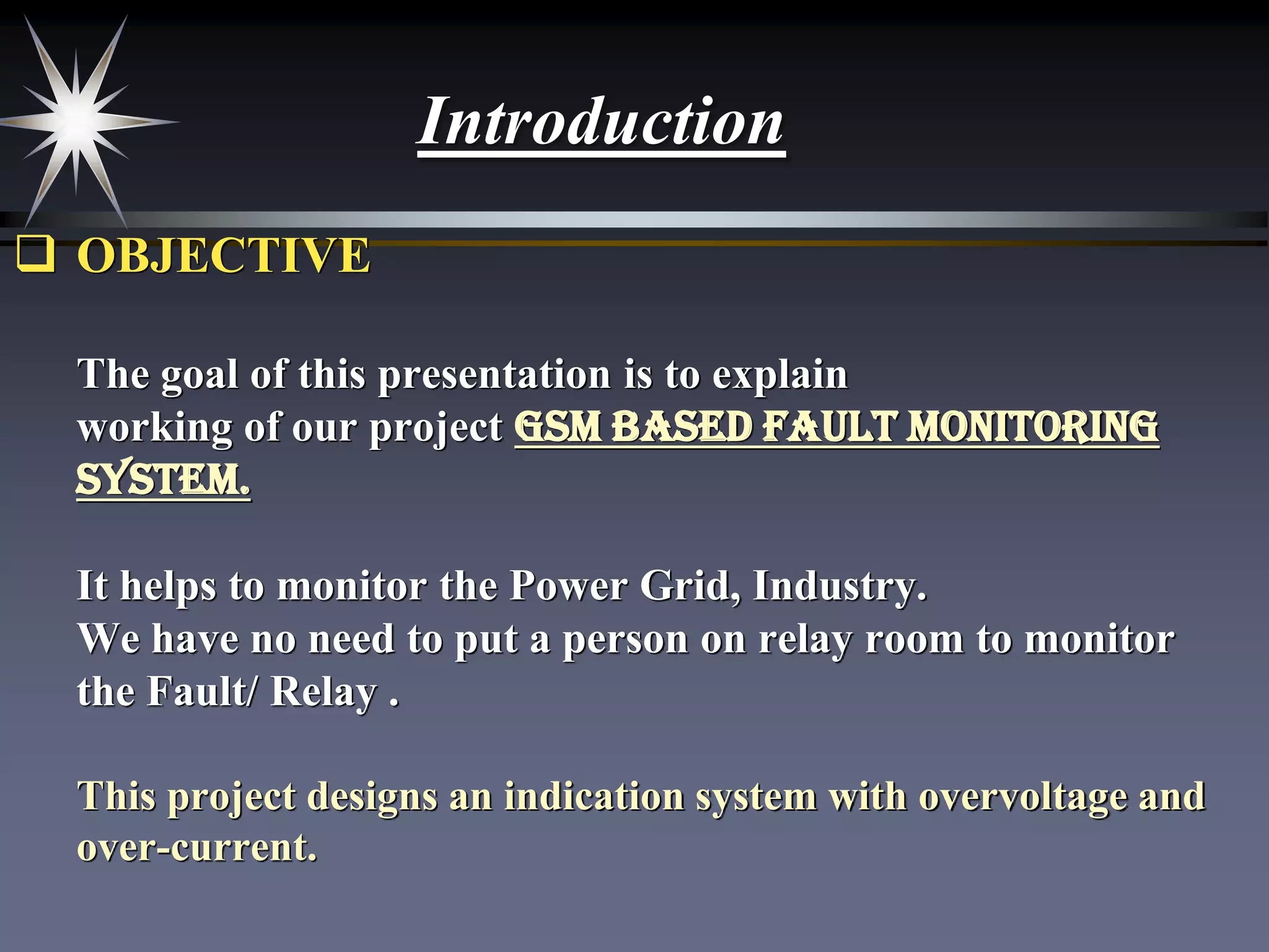
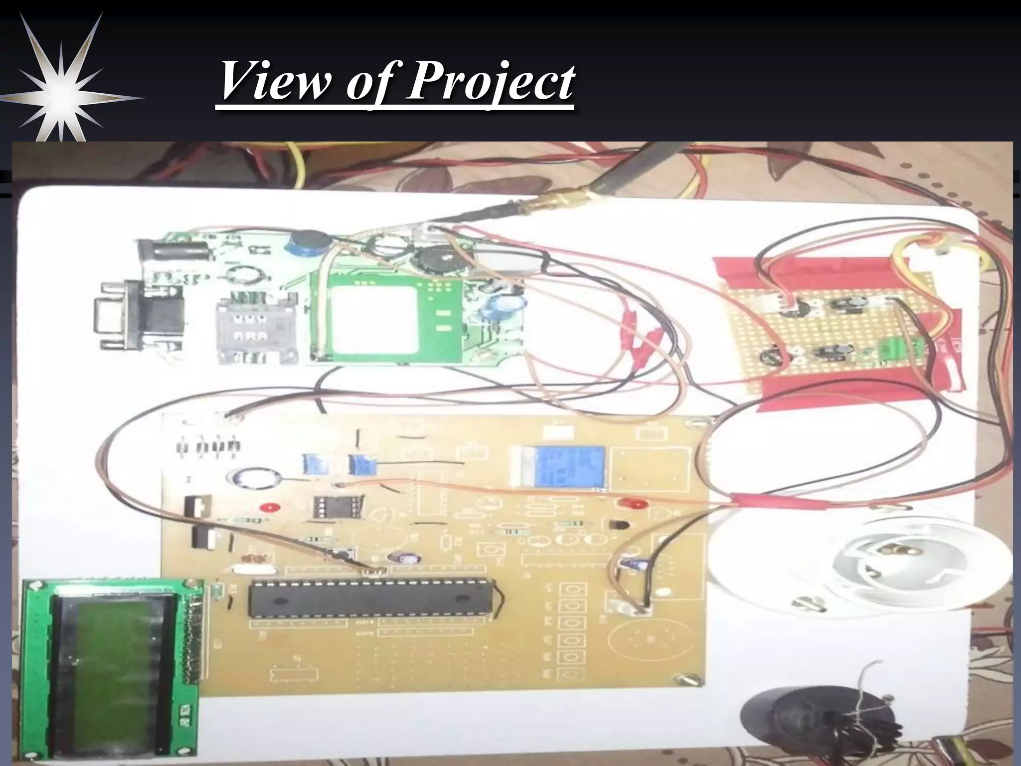

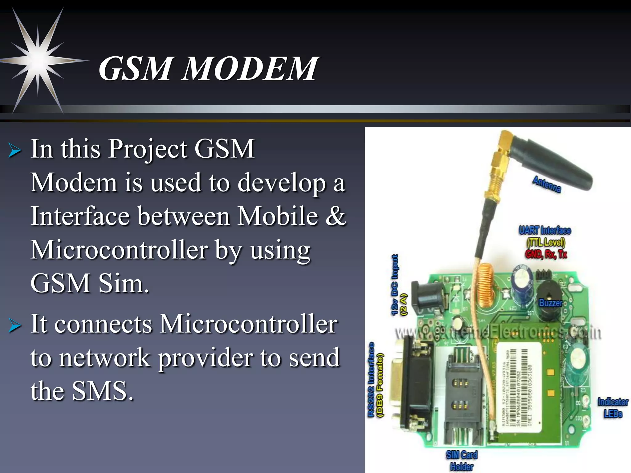
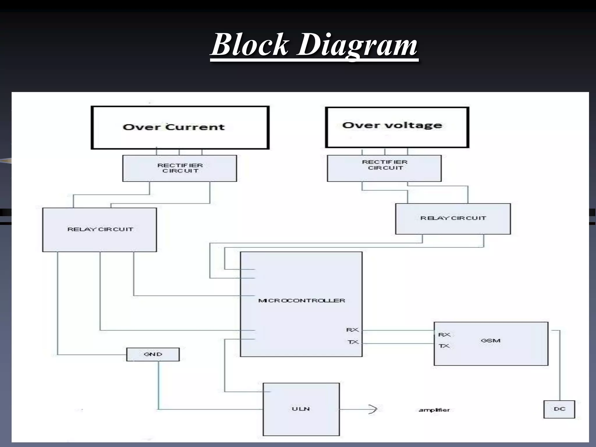
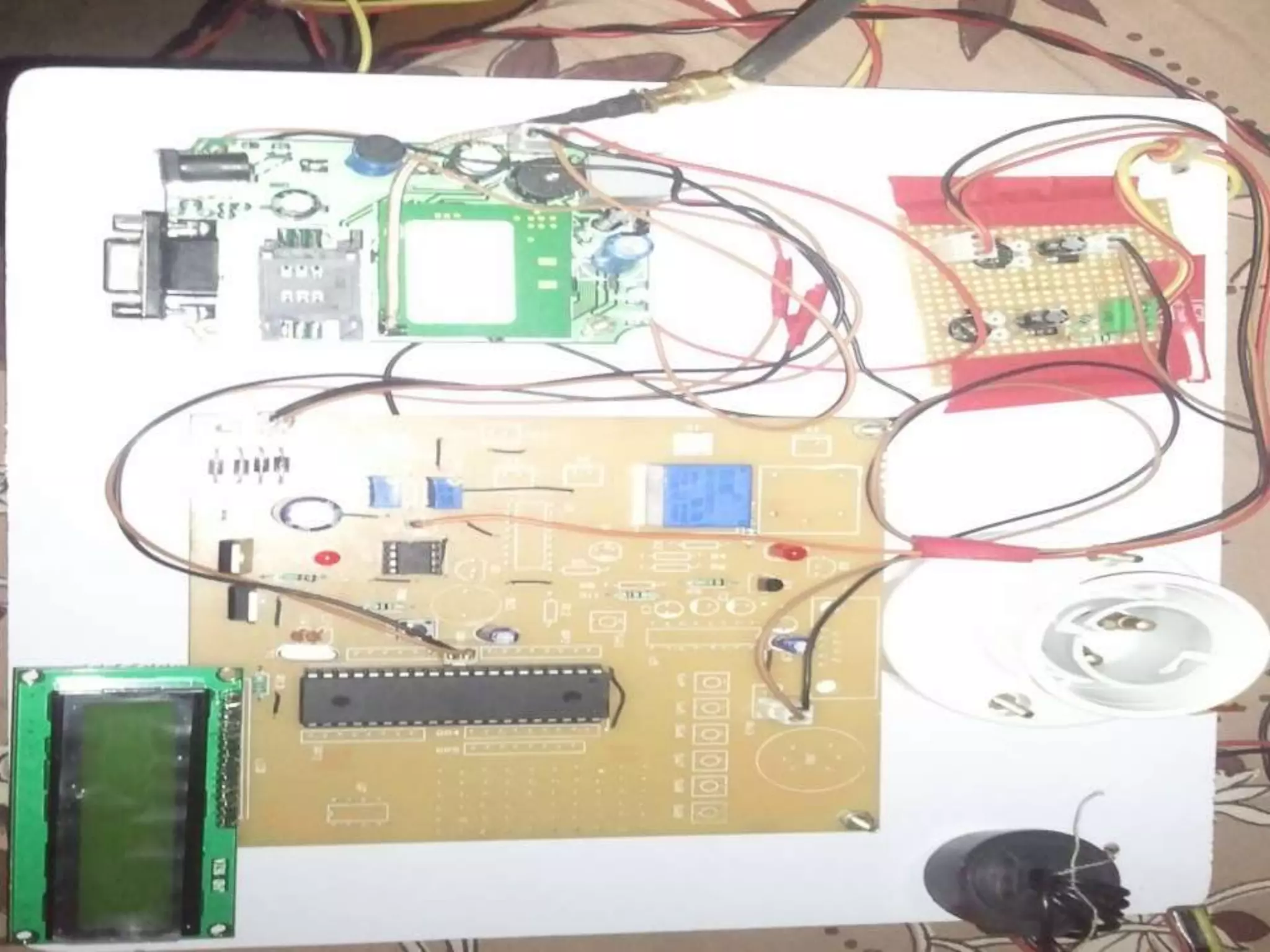
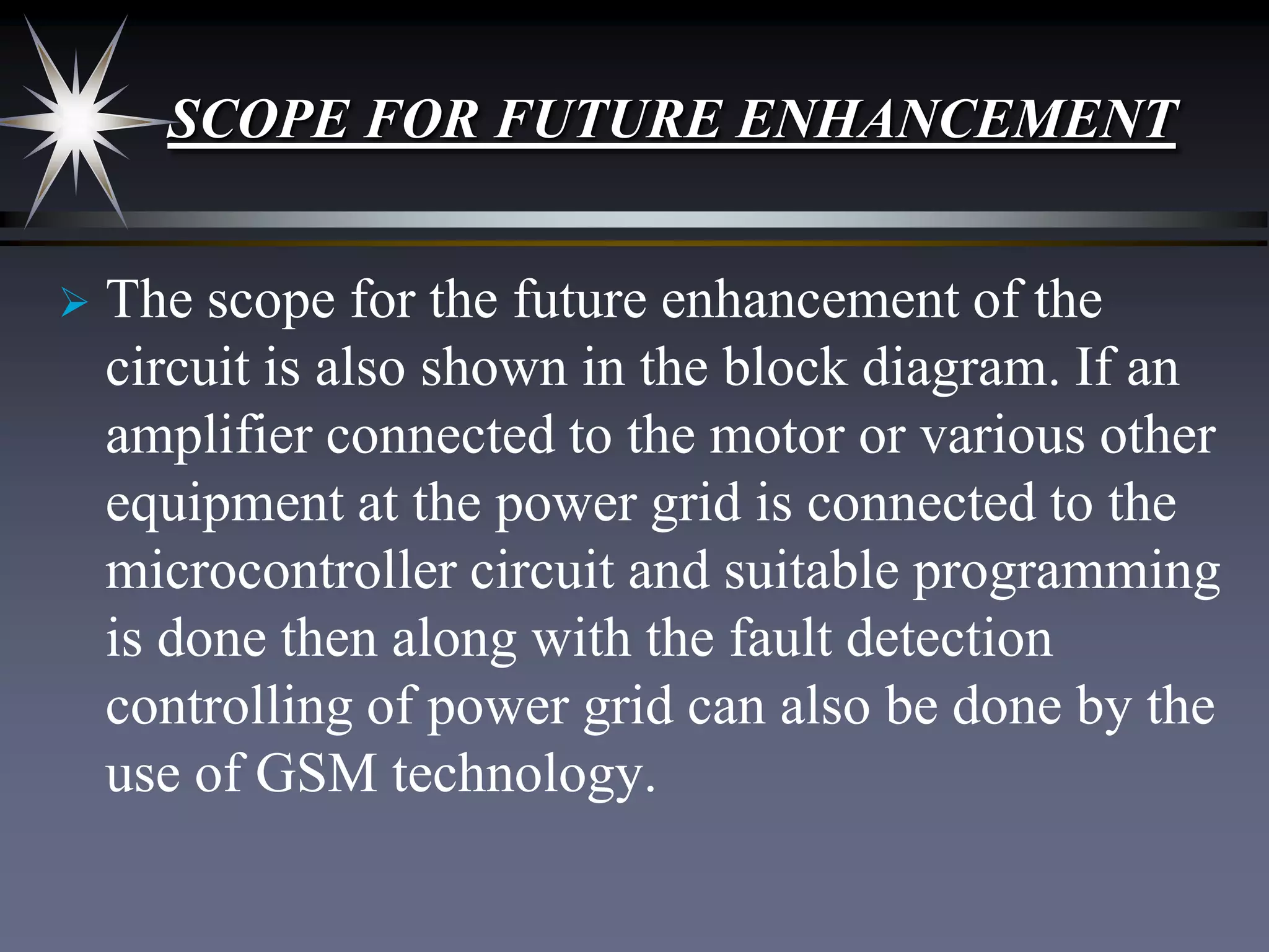
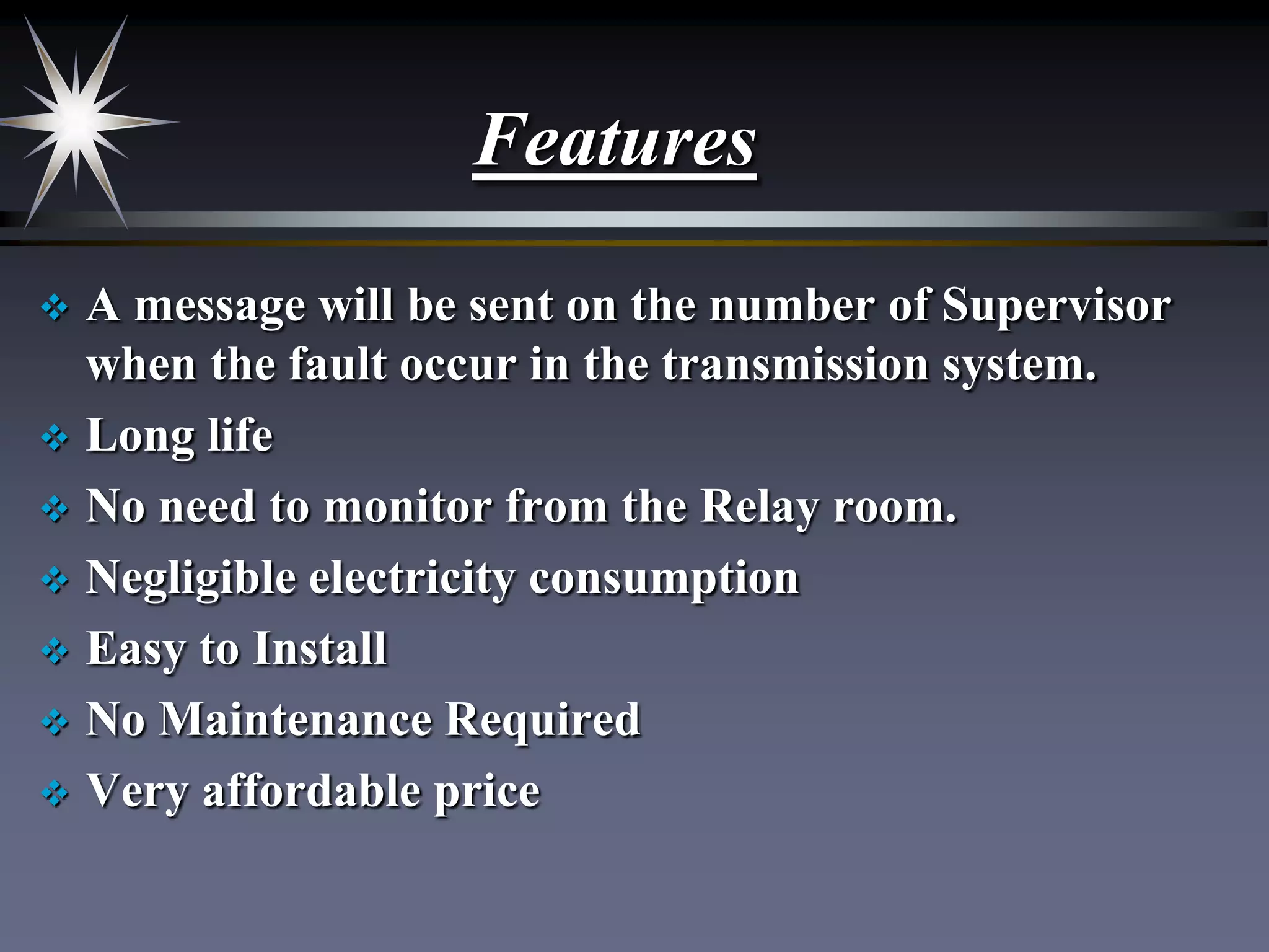


The document outlines a GSM-based fault monitoring system designed to monitor power grids and industries without the need for human presence in relay rooms. It describes the components used, including microcontrollers and GSM modems, and explains the system's functionality to send SMS alerts upon fault detection. The project highlights its features, areas of application, and emphasizes future enhancement possibilities for better control and monitoring.


![Vibe Coding vs. Spec-Driven Development [Free Meetup]](https://cdn.slidesharecdn.com/ss_thumbnails/vibecodingvsspecdrivendevelopment-251209105622-43f455e7-thumbnail.jpg?width=640&height=640&fit=bounds)


