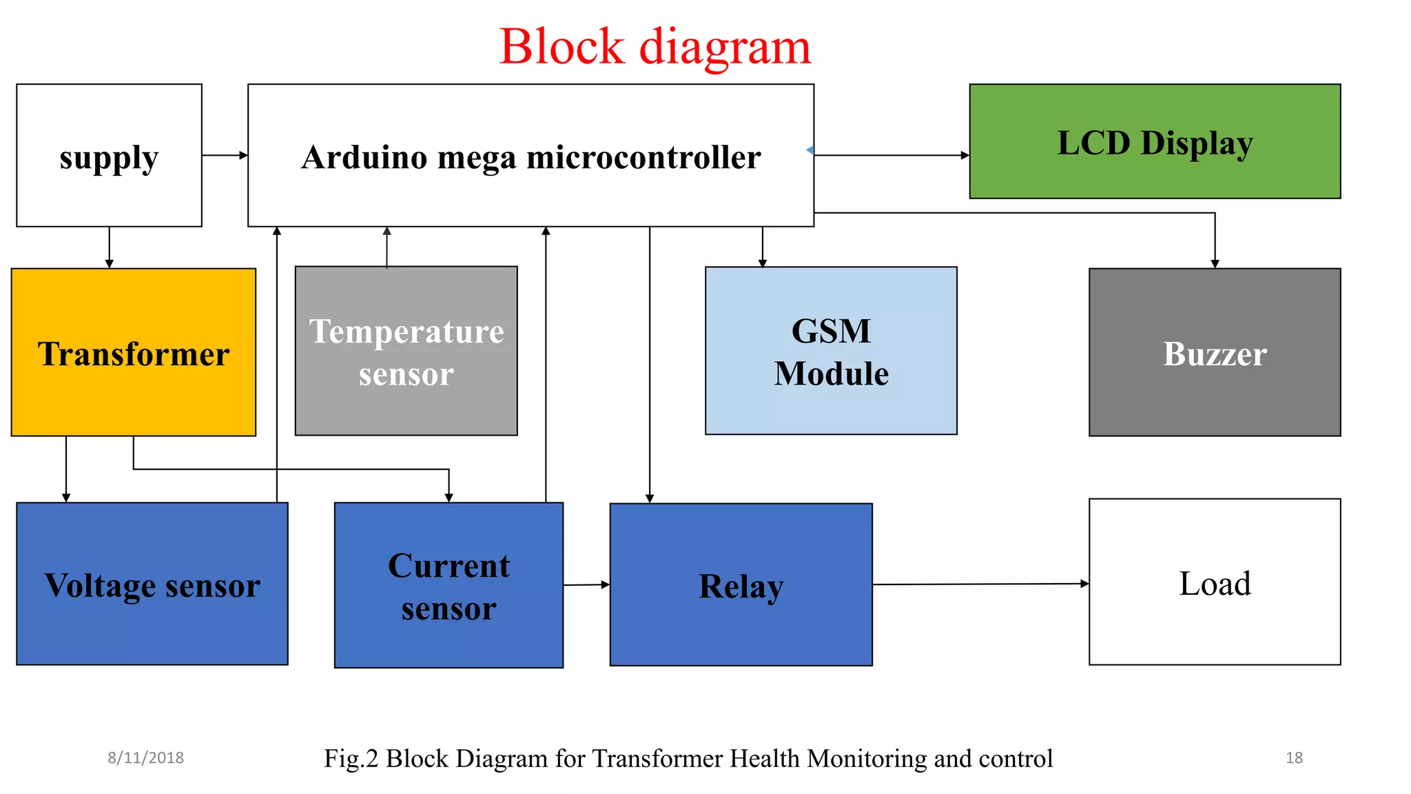
A Project Seminar
on
AN EXPERIMENTAL SETUP FOR TRANSFORMER
PROTECTION USING ARDUINO
Under the guidance of
Dr. Avagaddi Prasad, M.Tech., Ph.D.
Associate Professor,
Dept. of EEE,
SVEC.
Presented by
14121A02N3(V. JAYASREE)
15125A0223(K. SUKANYA)
15125A0251(U.DILEEP KUMAR)
14121A02N5(V. VENKATA TEJA)
14121A02P0(Y. VINAY)
DEPARTMENT OF ELECTRICALAND ELECTRONICS ENGINEERING
SREE VIDYANIKETHAN ENGINEERING COLLEGE (AUTONOMOUS)
RANGAMPET, TIRUPATI – 517 102
8/11/2018 1
CONTENTS
• Objective
• Introduction
• Literature survey
• Existing method
• Disadvantages of existing method
• Components used
• Block diagram
• Components specifications
• Proposed methodology
• Flow chart
• Tools used
• Theoretical calculations
• Results obtained
• References
8/11/2018 2
Objective
• To design a protective circuit for transformer, based on programmable
Arduino to monitor transformer temperature, voltage and current by using
sensors.
• To design an communication system using Arduino controlled GSM
module to transfer the over voltage, over current and over temperature
fault values to mobile devices.
8/11/2018 3
Introduction
• Transformers are a critical and expensive component of the power system.
• Transformer, which is used in different sizes, types, and connections.
• Therefore, the continuity of its operation is of vital importance in maintaining the
reliability of power supply.
• A power system is said to be faulty when an undesirable condition occurs in that power
system, where the undesirable condition might be short circuits, overcurrent,
overvoltage etc.
8/11/2018 4
Introduction (Contd.,)
• Any unscheduled repair work, especially replacement of a faulty transformer, is
very expensive and time consuming.
• Protection against fault in power systems is very essential and vital for reliable
performance.
• The type of protection used should minimize the time of disconnection for faults
within the transformer and to reduce the risk of failure to simplify eventual repair.
8/11/2018 5
Literature Survey
• Online condition monitoring system for substation and service transformer
[1]
To get maximum profit with minimum maintenance cost by developing a
condition based monitoring. It is useful to replace reactive and preventive
maintenance.
Advantage: It is cost effective, online and accurate tool as it proposes corrective
actions and the results are evaluated by comparing with the results obtained from
utility model.
Disadvantage: It can be applied only to transformers without any abnormal faults
such as detected by dissolved gas analysis.
8/11/2018 6
Literature Survey (Contd.,)
• Transformer health monitoring system [2]
As it is difficult to monitor the condition manually of every single transformer.
So, automatic data acquisition and transformer condition monitoring is issued.
It presents mobile embedded system to monitor load currents, over voltage,
transformer oil level and oil temperature by integrating GSM modem with single
chip micro controller and sensors installed at distribution transformer site.
This system is advanced step to the automation by diminishing human
dependency. As it is wireless, there is no need of large cables which is of high cost.
• A novel offline to online approach to detect transformer inter turn fault [3]
The time of acquisition and operation parameters is too long for ordinary
transformer but by using distribution transformer real time monitoring system to
detect all operation parameters in time.
8/11/2018 7
Literature Survey (Contd.,)
In ordinary transformers, detection of system itself is not reliable, device is instable,
poor anti jamming capability, low measurement accuracy but by using this method health of
transformers is known and helps the utilities to optimally use their transformers and keep it
in operation for longer period. so, that we can identify problems before any serious failure
which leads to a significant cost savings and great reliability.
It is an approach based on the use of transformer no load and light load current harmonic
analysis to detect the presence of an inter turn fault at the incipient stage. The presence
of fault is detected by performing a trend analysis, which is a special test for transformer
testing into an online method at light load conditions. Thus the necessity of complete
shutdown and dependency on expert opinion is eliminated.
8/11/2018 8
Literature Survey (Contd.,)
• Health index calculation for power transformer using technical and
economical parameters [4]
The overall health condition of working transformers are evaluated by technical
diagnostic tests and economical lifetime assessment of transformers investigation.
Two artificial intelligence models including artificial neural network and adaptive
neuro-fuzzy inference system models are presented to determine the health index for
transformers.
The technical and economical parameters are used as input parameters to develop
the models. Technical parameters are extracted from oil characteristics and dissolved
gas analysis of different transformers. Economical parameters are constructed with
transformer capital investments, maintenance and operating costs. The models can
be used to determine the health condition of transformers with high accuracy.
8/11/2018 9
Existing method
• Differential protection :
In this protection its makes use of current difference flowing through
different terminals of the transformer.
• Differential protection is a unit-type protection for a specified zone or
piece of equipment. It is based on the fact that it is only in the case of faults
internal to the zone that the differential current (difference between input
and output currents) will be high.
8/11/2018 10
Existing method (Contd.,)
Fig.1 Differential Protection [3]
8/11/2018 11
Disadvantages of existing method
• It is costliest method
• when the transformer tap changer is moved up and down with respect
to the middle point at which the relay is adjusted to, the differential
relay might initiate a trip signal without the presence of any fault. This
mal operation is caused by a spill current due to the impact of On Load
Tap Changer (OLTC).
8/11/2018 12
Disadvantages of existing method (Contd.,)
• The pilot wires used may vary in length due to which the unbalance in
the secondary circuit parameter (resistance) is created that results in
improper scheme.
• During heavy short circuit conditions the high current creates
saturation of flux in core of CT’s that lead to abnormal relaying.
8/11/2018 13
Proposed methodology (Contd.,)
• Arduino is the main component in this circuit. The circuit diagram of the
differential protection of transformer using arduino is shown.
• Here Arduino is used as a controlling device. Hall effect current sensor is used to
measure the current on the secondary side of the transformer and send the
corresponding voltage to the arduino.
• Output of the arduino is connected to the relay.
• Under normal operating conditions currents on secondary side of the transformer
is less than the predefined value .
8/11/2018 14
Proposed methodology (Contd.,)
• So, the proportionate voltages generated by the hall sensor will be less and the
proportionate voltages are generated by current sensors are given.
• Under normal operating conditions these voltage will be less in magnitude and
difference is zero. So, the Arduino gives no signal to the relay.
• Whenever extra load or an internal fault occur in transformer the currents seen by
the hall effect differs by same amount.
• If this current increased more than the predefined value then it is termed as
abnormal condition.
8/11/2018 15
Proposed methodology (Contd.,)
• If the temperature also increases more than the predefined value it is also
considered as the abnormal condition.
• Arduino give a signal to the relay according predefined program. As and when the
relay is activated by the Arduino the relay will activates the triggering circuit.
• Arduino will give trip signal to the relay board and which is connected in series
with the supply will open its contacts thus the supply to the hardware setup will be
disconnected.
• Arduino will also send a message signal to GSM module as predefined in the
Arduino program.
8/11/2018 16
Components used
• Transformer
• Arduino Mega
• Voltage sensor
• Current sensor
• Thermistor
• Relay
• GSM module
• Lcd
8/11/2018 17
Arduino mega microcontroller LCD Display
Voltage sensor
Current
sensor
supply
Temperature
sensor
Transformer
Relay
GSM
Module
Buzzer
Load
Fig.2 Block Diagram for Transformer Health Monitoring and control
Block diagram
8/11/2018 18
Components specifications
Step down transformer :
• It consists of two windings namely primary and secondary windings.
• Primary can be designated with the less gauge wire with more number of turns for
carrying low current high voltage power.
• Secondary is designated with high gauge wire with less number of turns for carrying high
current low voltage power.
• It works on the principle of faraday’s laws of electro magnetic induction.
• Rating of transformer used is 230/15v
8/11/2018 19
Components specifications (Contd.,)
LCD screen(LM016) :
• Arduino includes the liquid crystal library , which has a set of functions that
makes it very easy to interface with the parallel LCD that we are using.
• The set of functions include blinking the cursor, automatically scrolling text,
creating custom characters and changing the direction of text printing.
• It has 8 data pins, register select pin, read/write pin, enable pin, 𝑣𝑠𝑠 pin, 𝑣 𝑑𝑑 pin,
vo pin, Anode , Cathode pin.
8/11/2018 20
Components specifications (Contd.,)
Relay :
• The relay is an electrically controllable switch.
• It allows the isolation of two separate sections of a system with two different
voltage sources.
• The electro magnetic relays have three components: the coil, spring and contacts.
• When current flows through the coil, a magnetic field is created around the coil
(the coil is energized), which causes the armature to be attracted to the coil. The
armature’s contact acts like a switch and closes or opens the circuit.
8/11/2018 21
Relay connection
Fig. 2 connection of relay
8/11/2018 22
Relay internal connection
Fig. 3 Internal connection of relay
8/11/2018 23
Components specifications (Contd.,)
Thermistor(LM35) :
• Thermistors, like RTDs, are thermally sensitive semiconductors whose resistance varies
with temperature.
• There are two types of thermistors negative temperature coefficient (NTC) thermistors,
whose resistance decreases with increasing temperature, and positive temperature
coefficient (PTC) thermistors, whose resistance increases with increasing temperature.
• NTC’s can exhibit coefficients of -10 kΩ/°C or more. In comparison, a 100 Ω platinum
RTD has a sensitivity of only 0.4 Ω/°C. A small size of the thermistor bead also yields a
very fast response to temperature changes.
8/11/2018 24
Temperature sensor connection(LM35DZ)
Fig .4 Connection of temperature sensor
8/11/2018 25
Temperature sensor internal structure
Fig . 5 Internal structure of temperature sensor
8/11/2018 26
Components specifications (Contd.,)
Arduino Mega:
• It is a combination of different electronic components on a single board.
• It is an open-source electronics prototyping platform based on flexible, easy-to-use
hardware and software.
• It has 54 digital input/output pins (of which 13 can be used as PWM outputs).
• 16 analog inputs, a 16 MHz crystal oscillator.
• A USB connection, a power jack , an ICSP header , and a reset button.
8/11/2018 27
Arduino mega 2560
Fig . 6 Architecture of arduino mega
8/11/2018 28
Components specifications (Contd.,)
Voltage sensor (ACS712) :
• It is based on the principle of resistive voltage design.
• It is a device that converts voltage measured between two points of an
electrical circuit into a physical signal proportional to the voltage.
• It can make the connector input voltage to 5 times smaller.
• It has the limit of Arduino analog input 5V DC only.
8/11/2018 29
Components specifications (Contd.,)
Current sensor :
The ACS712-05B can measure current upto ±5A and provides output sensitivity
of 185mV/A, which means for every 1A increase in the current through the
conduction terminals in the positive direction , the output voltage also rises by
185mV.
8/11/2018 30
Current sensor connection(ACS712)
Fig.7 Connection of current sensor
8/11/2018 31
Current sensor internal structure
Fig.8 Internal architecture of current sensor
8/11/2018 32
Components specifications (Contd.,)
GSM Module (SIM800L) :
• GSM means global system for mobile communication.
• GSM digitizes and compresses data ,then sends it down a channel with other streams of user data ,
each in it’s own time slot.
• It operates at either 900 MHz or 1800 MHz frequency brand.
• It is used to send sms to required number of phones by accepting inputs from the Arduino.
8/11/2018 33
GSM module connection
Fig.9 GSM module connection
8/11/2018 34
start
Initialize Arduino and gsm module
Read the pin A0, A1, A2
Compare the read value with stored
value
Check for results
Over
temperature
Over current Over voltage
High
?
High
?
High
?
yes yes yes
No No No
Flow chart
A CB
8/11/2018 35
Trip the relay and send sms to registered number
Lcd print the tripped values
stop
CBA
Fig.11 Transformer health monitoring and control flow chart
8/11/2018 36
Tools used
Fig.12 : Arduino software
8/11/2018 37
Fig.13 : Proteus software
Theoretical calculations
• 𝑡𝑒𝑚𝑝𝑎𝑟𝑒𝑡𝑢𝑟𝑒 =
𝑧×28
424
• 𝑐𝑢𝑟𝑟𝑒𝑛𝑡 =
𝑥×5
1024
• 𝑣𝑜𝑙𝑡𝑎𝑔𝑒 =
5×𝑦×(𝑟1+𝑟2)
1023×𝑟
Z = resistance measured across thermistor [1]
x = output voltage of hall sensor [1]
y = output voltage of voltage sensor [1]
r1 = 2000ohms & r2 = 3000ohms [1]
8/11/2018 38
Simulation results
8/11/2018 39Fig.14 : schematic figure
8/11/2018 40
Tripped at over current
Fig.15 : Tripped at over current
8/11/2018 41
Fig.16 : Tripped at over temperature
Tripped at over temperature
8/11/2018 42Fig.17 : Tripped at over voltage
Tripped at over voltage
8/11/2018 43
Fig.18 : Contunious flow
Continous flow
Experimental Result
8/11/2018 44
Tripped message from GSM to mobile :
8/11/2018 45
Conclusion
• The arduino based transformer protection achieves numerous advantages over the
existing systems in use:
1) fast response.
2) better isolation.
3) accurate detection of the fault.
8/11/2018 46
References
[1] Ballal, M. S., Jaiswal, G. C., Tutkane, D. R., Venikar, P. A., Mishra, M. K., & Suryawanshi, H. M. Online condition
monitoring system for substation and service transformers, IET Electric Power Applications, 2017, 11(7), 1187-1195.
[2] Patil R. V., Dhiraj Kalantre, Niranjan Hirugade, Arun More, Ashwinee Kakade, transformer health monitoring and
control through arduino, International Journal Of Electrical, Electronics And Data Communication, 2017, 5(1), 59-
62.
[3] Venikar, P. A., Ballal, M. S., Umre, B. S., & Suryawanshi, H. M. A novel offline to online approach to detect
transformer interturn fault. IEEE Transactions on Power Delivery, 2016, 31(2), 482-492.
[4] Zeinoddini-Meymand, H., & Vahidi, B. Health index calculation for power transformers using technical and
economical parameters. IET Science, Measurement & Technology, 2016, 10(7), 823-830.
[5] Campelo, F., Batista, L. S., Takahashi, R. H., Diniz, H. E., & Carrano, E. G. Multicriteria transformer asset
management with maintenance and planning perspectives. IET Generation, Transmission & Distribution, 2016 10(9),
2087-2097.
[6] Patil1 U. V., Kathe Mohan, Harkal Saurabh, Warhade Nilesh Transformer Health Condition Monitoring Using GSM
Technology, International Conference on Electrical, Computer and Communication Engineering, 2(2), 2016.
[7] Ma, H., Saha, T. K., Ekanayake, C., & Martin, D. Smart transformer for smart grid—Intelligent framework and
techniques for power transformer asset management. IEEE Transactions on Smart Grid, 2015, 6(2), 1026-1034.
8/11/2018 47
8/11/2018 48

project presentation on "THMC"

  • 1.
    A Project Seminar on ANEXPERIMENTAL SETUP FOR TRANSFORMER PROTECTION USING ARDUINO Under the guidance of Dr. Avagaddi Prasad, M.Tech., Ph.D. Associate Professor, Dept. of EEE, SVEC. Presented by 14121A02N3(V. JAYASREE) 15125A0223(K. SUKANYA) 15125A0251(U.DILEEP KUMAR) 14121A02N5(V. VENKATA TEJA) 14121A02P0(Y. VINAY) DEPARTMENT OF ELECTRICALAND ELECTRONICS ENGINEERING SREE VIDYANIKETHAN ENGINEERING COLLEGE (AUTONOMOUS) RANGAMPET, TIRUPATI – 517 102 8/11/2018 1
  • 2.
    CONTENTS • Objective • Introduction •Literature survey • Existing method • Disadvantages of existing method • Components used • Block diagram • Components specifications • Proposed methodology • Flow chart • Tools used • Theoretical calculations • Results obtained • References 8/11/2018 2
  • 3.
    Objective • To designa protective circuit for transformer, based on programmable Arduino to monitor transformer temperature, voltage and current by using sensors. • To design an communication system using Arduino controlled GSM module to transfer the over voltage, over current and over temperature fault values to mobile devices. 8/11/2018 3
  • 4.
    Introduction • Transformers area critical and expensive component of the power system. • Transformer, which is used in different sizes, types, and connections. • Therefore, the continuity of its operation is of vital importance in maintaining the reliability of power supply. • A power system is said to be faulty when an undesirable condition occurs in that power system, where the undesirable condition might be short circuits, overcurrent, overvoltage etc. 8/11/2018 4
  • 5.
    Introduction (Contd.,) • Anyunscheduled repair work, especially replacement of a faulty transformer, is very expensive and time consuming. • Protection against fault in power systems is very essential and vital for reliable performance. • The type of protection used should minimize the time of disconnection for faults within the transformer and to reduce the risk of failure to simplify eventual repair. 8/11/2018 5
  • 6.
    Literature Survey • Onlinecondition monitoring system for substation and service transformer [1] To get maximum profit with minimum maintenance cost by developing a condition based monitoring. It is useful to replace reactive and preventive maintenance. Advantage: It is cost effective, online and accurate tool as it proposes corrective actions and the results are evaluated by comparing with the results obtained from utility model. Disadvantage: It can be applied only to transformers without any abnormal faults such as detected by dissolved gas analysis. 8/11/2018 6
  • 7.
    Literature Survey (Contd.,) •Transformer health monitoring system [2] As it is difficult to monitor the condition manually of every single transformer. So, automatic data acquisition and transformer condition monitoring is issued. It presents mobile embedded system to monitor load currents, over voltage, transformer oil level and oil temperature by integrating GSM modem with single chip micro controller and sensors installed at distribution transformer site. This system is advanced step to the automation by diminishing human dependency. As it is wireless, there is no need of large cables which is of high cost. • A novel offline to online approach to detect transformer inter turn fault [3] The time of acquisition and operation parameters is too long for ordinary transformer but by using distribution transformer real time monitoring system to detect all operation parameters in time. 8/11/2018 7
  • 8.
    Literature Survey (Contd.,) Inordinary transformers, detection of system itself is not reliable, device is instable, poor anti jamming capability, low measurement accuracy but by using this method health of transformers is known and helps the utilities to optimally use their transformers and keep it in operation for longer period. so, that we can identify problems before any serious failure which leads to a significant cost savings and great reliability. It is an approach based on the use of transformer no load and light load current harmonic analysis to detect the presence of an inter turn fault at the incipient stage. The presence of fault is detected by performing a trend analysis, which is a special test for transformer testing into an online method at light load conditions. Thus the necessity of complete shutdown and dependency on expert opinion is eliminated. 8/11/2018 8
  • 9.
    Literature Survey (Contd.,) •Health index calculation for power transformer using technical and economical parameters [4] The overall health condition of working transformers are evaluated by technical diagnostic tests and economical lifetime assessment of transformers investigation. Two artificial intelligence models including artificial neural network and adaptive neuro-fuzzy inference system models are presented to determine the health index for transformers. The technical and economical parameters are used as input parameters to develop the models. Technical parameters are extracted from oil characteristics and dissolved gas analysis of different transformers. Economical parameters are constructed with transformer capital investments, maintenance and operating costs. The models can be used to determine the health condition of transformers with high accuracy. 8/11/2018 9
  • 10.
    Existing method • Differentialprotection : In this protection its makes use of current difference flowing through different terminals of the transformer. • Differential protection is a unit-type protection for a specified zone or piece of equipment. It is based on the fact that it is only in the case of faults internal to the zone that the differential current (difference between input and output currents) will be high. 8/11/2018 10
  • 11.
    Existing method (Contd.,) Fig.1Differential Protection [3] 8/11/2018 11
  • 12.
    Disadvantages of existingmethod • It is costliest method • when the transformer tap changer is moved up and down with respect to the middle point at which the relay is adjusted to, the differential relay might initiate a trip signal without the presence of any fault. This mal operation is caused by a spill current due to the impact of On Load Tap Changer (OLTC). 8/11/2018 12
  • 13.
    Disadvantages of existingmethod (Contd.,) • The pilot wires used may vary in length due to which the unbalance in the secondary circuit parameter (resistance) is created that results in improper scheme. • During heavy short circuit conditions the high current creates saturation of flux in core of CT’s that lead to abnormal relaying. 8/11/2018 13
  • 14.
    Proposed methodology (Contd.,) •Arduino is the main component in this circuit. The circuit diagram of the differential protection of transformer using arduino is shown. • Here Arduino is used as a controlling device. Hall effect current sensor is used to measure the current on the secondary side of the transformer and send the corresponding voltage to the arduino. • Output of the arduino is connected to the relay. • Under normal operating conditions currents on secondary side of the transformer is less than the predefined value . 8/11/2018 14
  • 15.
    Proposed methodology (Contd.,) •So, the proportionate voltages generated by the hall sensor will be less and the proportionate voltages are generated by current sensors are given. • Under normal operating conditions these voltage will be less in magnitude and difference is zero. So, the Arduino gives no signal to the relay. • Whenever extra load or an internal fault occur in transformer the currents seen by the hall effect differs by same amount. • If this current increased more than the predefined value then it is termed as abnormal condition. 8/11/2018 15
  • 16.
    Proposed methodology (Contd.,) •If the temperature also increases more than the predefined value it is also considered as the abnormal condition. • Arduino give a signal to the relay according predefined program. As and when the relay is activated by the Arduino the relay will activates the triggering circuit. • Arduino will give trip signal to the relay board and which is connected in series with the supply will open its contacts thus the supply to the hardware setup will be disconnected. • Arduino will also send a message signal to GSM module as predefined in the Arduino program. 8/11/2018 16
  • 17.
    Components used • Transformer •Arduino Mega • Voltage sensor • Current sensor • Thermistor • Relay • GSM module • Lcd 8/11/2018 17
  • 18.
    Arduino mega microcontrollerLCD Display Voltage sensor Current sensor supply Temperature sensor Transformer Relay GSM Module Buzzer Load Fig.2 Block Diagram for Transformer Health Monitoring and control Block diagram 8/11/2018 18
  • 19.
    Components specifications Step downtransformer : • It consists of two windings namely primary and secondary windings. • Primary can be designated with the less gauge wire with more number of turns for carrying low current high voltage power. • Secondary is designated with high gauge wire with less number of turns for carrying high current low voltage power. • It works on the principle of faraday’s laws of electro magnetic induction. • Rating of transformer used is 230/15v 8/11/2018 19
  • 20.
    Components specifications (Contd.,) LCDscreen(LM016) : • Arduino includes the liquid crystal library , which has a set of functions that makes it very easy to interface with the parallel LCD that we are using. • The set of functions include blinking the cursor, automatically scrolling text, creating custom characters and changing the direction of text printing. • It has 8 data pins, register select pin, read/write pin, enable pin, 𝑣𝑠𝑠 pin, 𝑣 𝑑𝑑 pin, vo pin, Anode , Cathode pin. 8/11/2018 20
  • 21.
    Components specifications (Contd.,) Relay: • The relay is an electrically controllable switch. • It allows the isolation of two separate sections of a system with two different voltage sources. • The electro magnetic relays have three components: the coil, spring and contacts. • When current flows through the coil, a magnetic field is created around the coil (the coil is energized), which causes the armature to be attracted to the coil. The armature’s contact acts like a switch and closes or opens the circuit. 8/11/2018 21
  • 22.
    Relay connection Fig. 2connection of relay 8/11/2018 22
  • 23.
    Relay internal connection Fig.3 Internal connection of relay 8/11/2018 23
  • 24.
    Components specifications (Contd.,) Thermistor(LM35): • Thermistors, like RTDs, are thermally sensitive semiconductors whose resistance varies with temperature. • There are two types of thermistors negative temperature coefficient (NTC) thermistors, whose resistance decreases with increasing temperature, and positive temperature coefficient (PTC) thermistors, whose resistance increases with increasing temperature. • NTC’s can exhibit coefficients of -10 kΩ/°C or more. In comparison, a 100 Ω platinum RTD has a sensitivity of only 0.4 Ω/°C. A small size of the thermistor bead also yields a very fast response to temperature changes. 8/11/2018 24
  • 25.
    Temperature sensor connection(LM35DZ) Fig.4 Connection of temperature sensor 8/11/2018 25
  • 26.
    Temperature sensor internalstructure Fig . 5 Internal structure of temperature sensor 8/11/2018 26
  • 27.
    Components specifications (Contd.,) ArduinoMega: • It is a combination of different electronic components on a single board. • It is an open-source electronics prototyping platform based on flexible, easy-to-use hardware and software. • It has 54 digital input/output pins (of which 13 can be used as PWM outputs). • 16 analog inputs, a 16 MHz crystal oscillator. • A USB connection, a power jack , an ICSP header , and a reset button. 8/11/2018 27
  • 28.
    Arduino mega 2560 Fig. 6 Architecture of arduino mega 8/11/2018 28
  • 29.
    Components specifications (Contd.,) Voltagesensor (ACS712) : • It is based on the principle of resistive voltage design. • It is a device that converts voltage measured between two points of an electrical circuit into a physical signal proportional to the voltage. • It can make the connector input voltage to 5 times smaller. • It has the limit of Arduino analog input 5V DC only. 8/11/2018 29
  • 30.
    Components specifications (Contd.,) Currentsensor : The ACS712-05B can measure current upto ±5A and provides output sensitivity of 185mV/A, which means for every 1A increase in the current through the conduction terminals in the positive direction , the output voltage also rises by 185mV. 8/11/2018 30
  • 31.
    Current sensor connection(ACS712) Fig.7Connection of current sensor 8/11/2018 31
  • 32.
    Current sensor internalstructure Fig.8 Internal architecture of current sensor 8/11/2018 32
  • 33.
    Components specifications (Contd.,) GSMModule (SIM800L) : • GSM means global system for mobile communication. • GSM digitizes and compresses data ,then sends it down a channel with other streams of user data , each in it’s own time slot. • It operates at either 900 MHz or 1800 MHz frequency brand. • It is used to send sms to required number of phones by accepting inputs from the Arduino. 8/11/2018 33
  • 34.
    GSM module connection Fig.9GSM module connection 8/11/2018 34
  • 35.
    start Initialize Arduino andgsm module Read the pin A0, A1, A2 Compare the read value with stored value Check for results Over temperature Over current Over voltage High ? High ? High ? yes yes yes No No No Flow chart A CB 8/11/2018 35
  • 36.
    Trip the relayand send sms to registered number Lcd print the tripped values stop CBA Fig.11 Transformer health monitoring and control flow chart 8/11/2018 36
  • 37.
    Tools used Fig.12 :Arduino software 8/11/2018 37 Fig.13 : Proteus software
  • 38.
    Theoretical calculations • 𝑡𝑒𝑚𝑝𝑎𝑟𝑒𝑡𝑢𝑟𝑒= 𝑧×28 424 • 𝑐𝑢𝑟𝑟𝑒𝑛𝑡 = 𝑥×5 1024 • 𝑣𝑜𝑙𝑡𝑎𝑔𝑒 = 5×𝑦×(𝑟1+𝑟2) 1023×𝑟 Z = resistance measured across thermistor [1] x = output voltage of hall sensor [1] y = output voltage of voltage sensor [1] r1 = 2000ohms & r2 = 3000ohms [1] 8/11/2018 38
  • 39.
  • 40.
    8/11/2018 40 Tripped atover current Fig.15 : Tripped at over current
  • 41.
    8/11/2018 41 Fig.16 :Tripped at over temperature Tripped at over temperature
  • 42.
    8/11/2018 42Fig.17 :Tripped at over voltage Tripped at over voltage
  • 43.
    8/11/2018 43 Fig.18 :Contunious flow Continous flow
  • 44.
  • 45.
    Tripped message fromGSM to mobile : 8/11/2018 45
  • 46.
    Conclusion • The arduinobased transformer protection achieves numerous advantages over the existing systems in use: 1) fast response. 2) better isolation. 3) accurate detection of the fault. 8/11/2018 46
  • 47.
    References [1] Ballal, M.S., Jaiswal, G. C., Tutkane, D. R., Venikar, P. A., Mishra, M. K., & Suryawanshi, H. M. Online condition monitoring system for substation and service transformers, IET Electric Power Applications, 2017, 11(7), 1187-1195. [2] Patil R. V., Dhiraj Kalantre, Niranjan Hirugade, Arun More, Ashwinee Kakade, transformer health monitoring and control through arduino, International Journal Of Electrical, Electronics And Data Communication, 2017, 5(1), 59- 62. [3] Venikar, P. A., Ballal, M. S., Umre, B. S., & Suryawanshi, H. M. A novel offline to online approach to detect transformer interturn fault. IEEE Transactions on Power Delivery, 2016, 31(2), 482-492. [4] Zeinoddini-Meymand, H., & Vahidi, B. Health index calculation for power transformers using technical and economical parameters. IET Science, Measurement & Technology, 2016, 10(7), 823-830. [5] Campelo, F., Batista, L. S., Takahashi, R. H., Diniz, H. E., & Carrano, E. G. Multicriteria transformer asset management with maintenance and planning perspectives. IET Generation, Transmission & Distribution, 2016 10(9), 2087-2097. [6] Patil1 U. V., Kathe Mohan, Harkal Saurabh, Warhade Nilesh Transformer Health Condition Monitoring Using GSM Technology, International Conference on Electrical, Computer and Communication Engineering, 2(2), 2016. [7] Ma, H., Saha, T. K., Ekanayake, C., & Martin, D. Smart transformer for smart grid—Intelligent framework and techniques for power transformer asset management. IEEE Transactions on Smart Grid, 2015, 6(2), 1026-1034. 8/11/2018 47
  • 48.