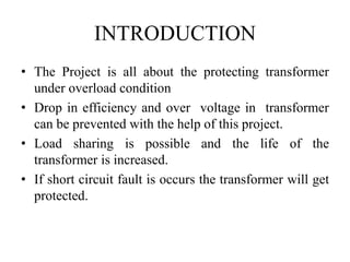
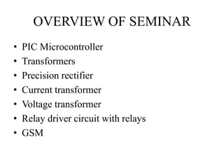
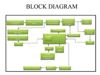
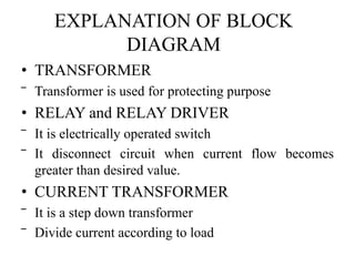
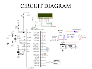
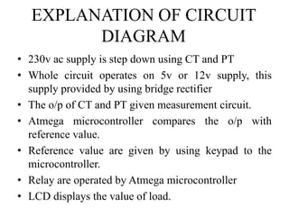
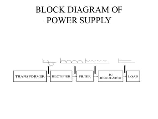
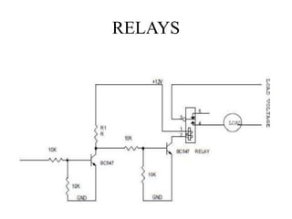
IPCOWALA INSTITUTE OF ENGINEERING TECHNOLOGY 
(DEP.:- ELECTRICAL & ELECTRONICS ENGINEERING) 
Transformer Protection using 
Microcontroller and GSM 
Technology 
PREPARED BY: 
KARTIK PATEL
CONTENT 
• INTRODUCTION 
• OVERVIEW OF 
SEMINAR 
• OBJECTIVES 
• BLOCK DIAGRAM 
• CIRCUIT DIAGRAM 
• POWER SUPPLY 
• TRANSFORMER 
• RECTIFIER 
• BRIDGE RECTIFRER 
• MICROCONTROLLER 
• VOLTAGE MEASUREMENT 
• CURRENT MEASUREMENT 
• RELAYS 
• ADVANTAGES 
• DISADVANTAGES 
• FUTURE SCOPE 
• REFERENCES 
• THANK YOU
INTRODUCTION 
• The Project is all about the protecting transformer 
under overload condition 
• Drop in efficiency and over voltage in transformer 
can be prevented with the help of this project. 
• Load sharing is possible and the life of the 
transformer is increased. 
• If short circuit fault is occurs the transformer will get 
protected.
OVERVIEW OF SEMINAR 
• PIC Microcontroller 
• Transformers 
• Precision rectifier 
• Current transformer 
• Voltage transformer 
• Relay driver circuit with relays 
• GSM
OBJECTIVES 
• The main aim of the project is transformer sharing 
whenever load is increased for certain value and also 
sending this change in information to the respective 
authority via SMS by using GSM modem. 
• The objective of this project is to protect the 
Domestic supply and Power Transformers from over 
load power.
BLOCK DIAGRAM
EXPLANATION OF BLOCK 
DIAGRAM 
• TRANSFORMER 
‾ Transformer is used for protecting purpose 
• RELAY and RELAY DRIVER 
‾ It is electrically operated switch 
‾ It disconnect circuit when current flow becomes 
greater than desired value. 
• CURRENT TRANSFORMER 
‾ It is a step down transformer 
‾ Divide current according to load
BLOCK DIAGRAM Cont’d 
• Precision rectifier 
– It converts AC current to DC current. 
• Microcontroller 
– It compares voltage with reference value. 
– It drive a relay circuit as per the reference value 
and actual value. 
• GSM Modem 
– It performs digital cellular communication. 
– It gives digital info to respective authority via 
SMS.
CIRCUIT DIAGRAM
EXPLANATION OF CIRCUIT 
DIAGRAM 
• 230v ac supply is step down using CT and PT 
• Whole circuit operates on 5v or 12v supply, this 
supply provided by using bridge rectifier 
• The o/p of CT and PT given measurement circuit. 
• Atmega microcontroller compares the o/p with 
reference value. 
• Reference value are given by using keypad to the 
microcontroller. 
• Relay are operated by Atmega microcontroller 
• LCD displays the value of load.
PARTS OF CIRCUIT DIAGRAM 
• Power supply 
• Atmega328/168 microcontroller 
• Current measurement 
• Voltage measurement 
• Relay
POWER SUPPLY 
• Whole circuitry work on +5v, 12v & -12v DC power 
supply of 230v AC is applied to the transformer. 
• By using transformer, rectifier, filters, Ic regulators, 
etc. we get the desired output.
BLOCK DIAGRAM OF 
POWER SUPPLY
DISCRIPTION OF POWER 
SUPPLY 
• Transformer 
– 230v AC is step down to 5v and 12v as per 
requirement of circuitry. 
• Rectifier 
– It converts the AC supply into pulsating DC supply. 
• Filters 
– It removes the ripples from the DC supply which 
are coming from the rectifier. 
• IC regulator 
– IC regulator is providing the fixed DC voltage 
which load (i.e. relay and microcontroller) required.
TRANSFORMERS
TRANSFORMER Cont’d 
• An electrically isolated but magnetically coupled 
device, which transformed electrical power from one 
circuit to another circuit without changing frequency 
is called TRANSFORMER. 
• There are basically two types 
‾ Step Down transformer 
‾ Step Up transformer 
• We are using step down transformer 
• CT and PT are step down transformer
RECTIFIER 
• It is a circuit which converts AC to DC. 
• Output of a rectifier is not pure DC, it is pulsating DC. 
• There are basically two types of rectifier 
– Half wave rectifier 
– Full wave rectifier 
-Bridge rectifier 
• We are using Bridge rectifier to get desired DC output 
voltage of +5v,+12v, and -12v
BRIDGE RECTIFIER
WORKING OF BRIDGE RECTIFIER 
• At +ve half cycle there is +ve potential at node A and 
–ve potential at node B. 
• Due to which D1 and D4 are in forward bias and D2 
and D3 are work in reverse bias, we get DC voltage of 
+half cycle. 
• Similarly at –ve half cycle there is +ve potential at 
node B and –ve potential at node A. 
• Due to which D2 and D3 are in forward bias and D1 
and D4 are work in reverse bias, we get DC voltage of 
–ve half cycle. 
• Finally we get o/p that is pulsating DC.
ATMEGA MICROCONTROLLER 
• The ATmega328 is a low-power CMOS 8-bit 
microcontroller based on the AVR enhanced RISC 
architecture. 
• Atmega are popular for low cost , wide availability, 
large user base, free development tools and serial 
programming (and reprogramming with flash 
memory) capability so we are using this 
microcontroller.
PIN CONFIGURATION
VOLTAGE MEASUREMENT
VOLTAGE MEASUREMENT Cont’d 
• Potential transformer(PT) is use to monitor the supply 
voltage. 
• Supply voltage that has to be monitor is step down by 
PT. 
• The step down voltage is rectified by bridge rectifier. 
• Different DC voltage which required by relay and 
MC are to be given by using IC regulator . 
• The function of voltage measurement is to provide 
step down voltage.
CURRENT MEASUREMENT
CURRENT MEASUREMENT Cont’d 
• Current transformer(CT) is use to step down current 
• The circuit is design to monitor the supply current 
• The step down current is converted by voltage with 
the help of shunt register
RELAYS
RELAYS Cont’d 
• It is an electromagnetic device which is use as switch 
• It has a magnetic coil which is use to connect or 
disconnect the transformer 
• It is electrically operated switch 
• It disconnect circuit when current flow becomes greater 
than desired value 
• Both relays are controlled by relay driver 
• If the current consumption is above 50% then the lower 
relay get switch OFF through the relay driver circuit. 
• IF the current consumption is above 80% then the all 
relay get switch OFF through the relay driver circuit.
ADVANTAGES 
• It prevents circuitry from damage 
• Avoid interruption in power supply 
• Remove power black out at pick hours 
• Accident prevention 
• Transformer safety
DISADVANTAGES 
• Cost of whole circuitry will increased 
• Circuitry become bulky
FUTURE SCOPE 
• GSM-(global system for mobile communication) 
– GSM is globally accepted standard for digital cellular 
communication 
– Frequency range 900MHZ to 1990MHZ 
– PIC microcontroller sends actual load value to the 
authority via SMS by using GSM 
– In our project we are using only transmitter to 
transmit the data 
– In our project we are not yet get the required 
frequency GSM
REFERENCES 
• Electrical technology volume 3rd and 4th by- B. L. 
Theraja,1st edition 1959,reprint 2008 
• Advance microprocessor and microcontrollers by- A. P. 
Godse,3rd edition 2003 
• Linear integrated circuits J.S. Katre, 4th edition 2002 
• IEEE Transaction on Power Electronics, vol. 19, no. 6, 
November 2004 1551by-Mohammad N. Marwali, 
Member, IEEE, Jin-Woo Jung, Student Member, IEEE, 
and Ali Keyhani, Fellow, IEEE
THANK YOU

Transformer protection using microcontroller and gsm technology

  • 1.
    IPCOWALA INSTITUTE OFENGINEERING TECHNOLOGY (DEP.:- ELECTRICAL & ELECTRONICS ENGINEERING) Transformer Protection using Microcontroller and GSM Technology PREPARED BY: KARTIK PATEL
  • 2.
    CONTENT • INTRODUCTION • OVERVIEW OF SEMINAR • OBJECTIVES • BLOCK DIAGRAM • CIRCUIT DIAGRAM • POWER SUPPLY • TRANSFORMER • RECTIFIER • BRIDGE RECTIFRER • MICROCONTROLLER • VOLTAGE MEASUREMENT • CURRENT MEASUREMENT • RELAYS • ADVANTAGES • DISADVANTAGES • FUTURE SCOPE • REFERENCES • THANK YOU
  • 3.
    INTRODUCTION • TheProject is all about the protecting transformer under overload condition • Drop in efficiency and over voltage in transformer can be prevented with the help of this project. • Load sharing is possible and the life of the transformer is increased. • If short circuit fault is occurs the transformer will get protected.
  • 4.
    OVERVIEW OF SEMINAR • PIC Microcontroller • Transformers • Precision rectifier • Current transformer • Voltage transformer • Relay driver circuit with relays • GSM
  • 5.
    OBJECTIVES • Themain aim of the project is transformer sharing whenever load is increased for certain value and also sending this change in information to the respective authority via SMS by using GSM modem. • The objective of this project is to protect the Domestic supply and Power Transformers from over load power.
  • 6.
  • 7.
    EXPLANATION OF BLOCK DIAGRAM • TRANSFORMER ‾ Transformer is used for protecting purpose • RELAY and RELAY DRIVER ‾ It is electrically operated switch ‾ It disconnect circuit when current flow becomes greater than desired value. • CURRENT TRANSFORMER ‾ It is a step down transformer ‾ Divide current according to load
  • 8.
    BLOCK DIAGRAM Cont’d • Precision rectifier – It converts AC current to DC current. • Microcontroller – It compares voltage with reference value. – It drive a relay circuit as per the reference value and actual value. • GSM Modem – It performs digital cellular communication. – It gives digital info to respective authority via SMS.
  • 9.
  • 10.
    EXPLANATION OF CIRCUIT DIAGRAM • 230v ac supply is step down using CT and PT • Whole circuit operates on 5v or 12v supply, this supply provided by using bridge rectifier • The o/p of CT and PT given measurement circuit. • Atmega microcontroller compares the o/p with reference value. • Reference value are given by using keypad to the microcontroller. • Relay are operated by Atmega microcontroller • LCD displays the value of load.
  • 11.
    PARTS OF CIRCUITDIAGRAM • Power supply • Atmega328/168 microcontroller • Current measurement • Voltage measurement • Relay
  • 12.
    POWER SUPPLY •Whole circuitry work on +5v, 12v & -12v DC power supply of 230v AC is applied to the transformer. • By using transformer, rectifier, filters, Ic regulators, etc. we get the desired output.
  • 13.
    BLOCK DIAGRAM OF POWER SUPPLY
  • 14.
    DISCRIPTION OF POWER SUPPLY • Transformer – 230v AC is step down to 5v and 12v as per requirement of circuitry. • Rectifier – It converts the AC supply into pulsating DC supply. • Filters – It removes the ripples from the DC supply which are coming from the rectifier. • IC regulator – IC regulator is providing the fixed DC voltage which load (i.e. relay and microcontroller) required.
  • 15.
  • 16.
    TRANSFORMER Cont’d •An electrically isolated but magnetically coupled device, which transformed electrical power from one circuit to another circuit without changing frequency is called TRANSFORMER. • There are basically two types ‾ Step Down transformer ‾ Step Up transformer • We are using step down transformer • CT and PT are step down transformer
  • 17.
    RECTIFIER • Itis a circuit which converts AC to DC. • Output of a rectifier is not pure DC, it is pulsating DC. • There are basically two types of rectifier – Half wave rectifier – Full wave rectifier -Bridge rectifier • We are using Bridge rectifier to get desired DC output voltage of +5v,+12v, and -12v
  • 18.
  • 19.
    WORKING OF BRIDGERECTIFIER • At +ve half cycle there is +ve potential at node A and –ve potential at node B. • Due to which D1 and D4 are in forward bias and D2 and D3 are work in reverse bias, we get DC voltage of +half cycle. • Similarly at –ve half cycle there is +ve potential at node B and –ve potential at node A. • Due to which D2 and D3 are in forward bias and D1 and D4 are work in reverse bias, we get DC voltage of –ve half cycle. • Finally we get o/p that is pulsating DC.
  • 20.
    ATMEGA MICROCONTROLLER •The ATmega328 is a low-power CMOS 8-bit microcontroller based on the AVR enhanced RISC architecture. • Atmega are popular for low cost , wide availability, large user base, free development tools and serial programming (and reprogramming with flash memory) capability so we are using this microcontroller.
  • 21.
  • 22.
  • 23.
    VOLTAGE MEASUREMENT Cont’d • Potential transformer(PT) is use to monitor the supply voltage. • Supply voltage that has to be monitor is step down by PT. • The step down voltage is rectified by bridge rectifier. • Different DC voltage which required by relay and MC are to be given by using IC regulator . • The function of voltage measurement is to provide step down voltage.
  • 24.
  • 25.
    CURRENT MEASUREMENT Cont’d • Current transformer(CT) is use to step down current • The circuit is design to monitor the supply current • The step down current is converted by voltage with the help of shunt register
  • 26.
  • 27.
    RELAYS Cont’d •It is an electromagnetic device which is use as switch • It has a magnetic coil which is use to connect or disconnect the transformer • It is electrically operated switch • It disconnect circuit when current flow becomes greater than desired value • Both relays are controlled by relay driver • If the current consumption is above 50% then the lower relay get switch OFF through the relay driver circuit. • IF the current consumption is above 80% then the all relay get switch OFF through the relay driver circuit.
  • 28.
    ADVANTAGES • Itprevents circuitry from damage • Avoid interruption in power supply • Remove power black out at pick hours • Accident prevention • Transformer safety
  • 29.
    DISADVANTAGES • Costof whole circuitry will increased • Circuitry become bulky
  • 30.
    FUTURE SCOPE •GSM-(global system for mobile communication) – GSM is globally accepted standard for digital cellular communication – Frequency range 900MHZ to 1990MHZ – PIC microcontroller sends actual load value to the authority via SMS by using GSM – In our project we are using only transmitter to transmit the data – In our project we are not yet get the required frequency GSM
  • 31.
    REFERENCES • Electricaltechnology volume 3rd and 4th by- B. L. Theraja,1st edition 1959,reprint 2008 • Advance microprocessor and microcontrollers by- A. P. Godse,3rd edition 2003 • Linear integrated circuits J.S. Katre, 4th edition 2002 • IEEE Transaction on Power Electronics, vol. 19, no. 6, November 2004 1551by-Mohammad N. Marwali, Member, IEEE, Jin-Woo Jung, Student Member, IEEE, and Ali Keyhani, Fellow, IEEE
  • 32.