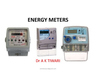
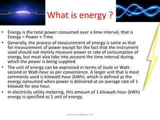
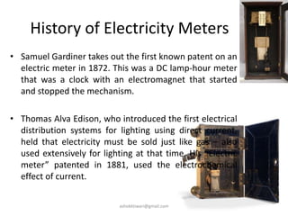
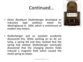
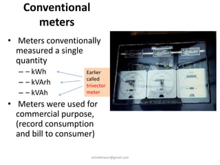
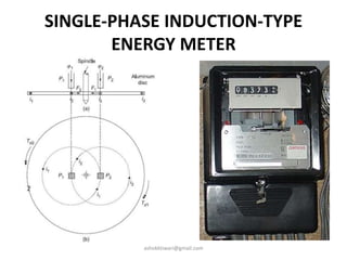
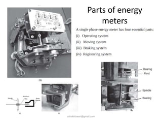
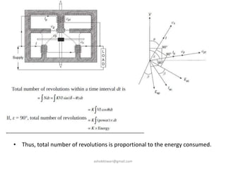
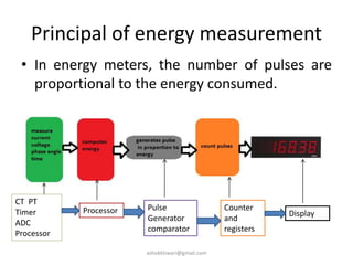
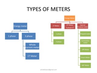
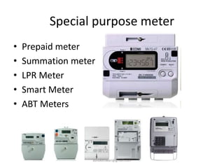
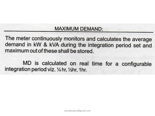
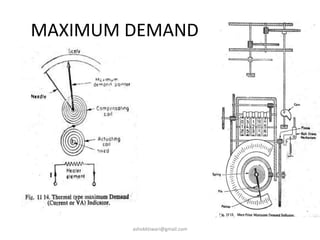
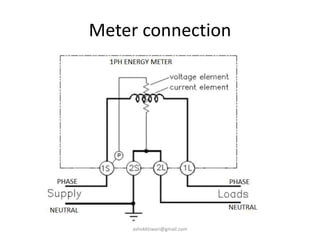
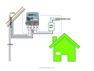
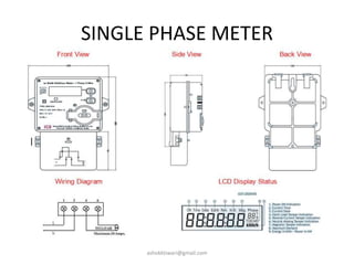
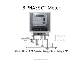
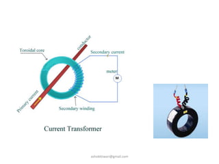
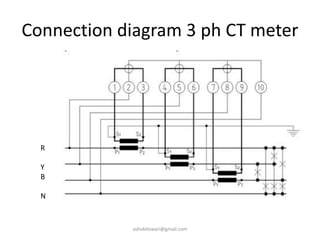
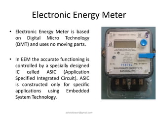
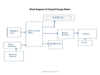
The document discusses energy meters and how they work. It provides information on:
1) The basic components and operating principles of induction-type energy meters, including how they measure power consumption over time using a rotating aluminum disc.
2) The history of electricity meters dating back to 1872, and how modern watthour meters developed from early designs.
3) Additional meter types like CT meters, electronic meters, and special purpose meters like prepaid and smart meters.
4) Key aspects of energy metering like accuracy classes, maximum demand calculation, and advanced metering functionality.
Power measurement is a valid technique to measure that how much the power is being transmitted through the entire system.
In this presentation you will estimate and understand the following objectives
Wattmeter as a device
Power measurement techniques
Classical based history
Construction of wattmeter
Working of Wattmeter
Power measurement of direct and indirect way
Power measurement in three phase applications
Applications of Wattmeter
What is islanding ?
Consider the power network as shown in fig.1
Now if we disconnect the line AB from the infinite transmission grid there will be an isolated region . The D1, D2 are power sources (eg : inverter , solar power cells ). The power generated in this region is fed to the island only.
We see that there no longer is any control over the island voltage at the bus X . Also there is no mechanism here for control of frequency.
This state is referred to as islanding.
This PPT explains about the circuit breaker, and its types. Then about the need and purpose of the circuit breaker. And finally the testing and types of testing of circuit breakers.
It is based on current transformer description
It's working and applications are present in it ,it also includes videos of it's windings and it's inrush ability of transformer, and also about instrument transformer and it's working with applications.Current transformers are used-in measuring high currents and connected with it in parallel to it
Installation, Testing and Troubleshooting of TransformersLiving Online
This will provide you with practical knowledge (including tips, tricks and tools) covering the fundamentals of power transformers and their testing. It will greatly assist you in communicating more effectively with your electrical engineering colleagues. At the end of this workshop, participants will be familiar with the importance of transformer testing and their purpose, the different kinds of transformer tests and their procedures and the practical applications of principals applied in transformer operation and maintenance.
WHO SHOULD ATTEND?
This workshop will be appropriate for the following professionals:
Electrical engineers
Maintenance engineers
Maintenance supervisors
Power electricians
Power engineers
MORE INFORMATION: http://www.idc-online.com/content/installation-testing-and-troubleshooting-transformers-24
Current Transformer and Potential TransformerRidwanul Hoque
One of the major difference between them is that the current transformer converts the high value of current into low value whereas the potential or voltage transformer converts the high value of voltages into low voltage.
This directional over current relay employs the principle of actuation of the relay....It has a metallic disc free to rotate between the poles of two...
TESCO's Owner Tom Lawton explores this intriguing topic in his recent EEI presentation. The evolution of DC applications leads to the evolution of DC Metering's form factors. 10/11/2022
NO1 Uk best vashikaran specialist in delhi vashikaran baba near me online vas...Amil Baba Dawood bangali
Contact with Dawood Bhai Just call on +92322-6382012 and we'll help you. We'll solve all your problems within 12 to 24 hours and with 101% guarantee and with astrology systematic. If you want to take any personal or professional advice then also you can call us on +92322-6382012 , ONLINE LOVE PROBLEM & Other all types of Daily Life Problem's.Then CALL or WHATSAPP us on +92322-6382012 and Get all these problems solutions here by Amil Baba DAWOOD BANGALI
#vashikaranspecialist #astrologer #palmistry #amliyaat #taweez #manpasandshadi #horoscope #spiritual #lovelife #lovespell #marriagespell#aamilbabainpakistan #amilbabainkarachi #powerfullblackmagicspell #kalajadumantarspecialist #realamilbaba #AmilbabainPakistan #astrologerincanada #astrologerindubai #lovespellsmaster #kalajaduspecialist #lovespellsthatwork #aamilbabainlahore#blackmagicformarriage #aamilbaba #kalajadu #kalailam #taweez #wazifaexpert #jadumantar #vashikaranspecialist #astrologer #palmistry #amliyaat #taweez #manpasandshadi #horoscope #spiritual #lovelife #lovespell #marriagespell#aamilbabainpakistan #amilbabainkarachi #powerfullblackmagicspell #kalajadumantarspecialist #realamilbaba #AmilbabainPakistan #astrologerincanada #astrologerindubai #lovespellsmaster #kalajaduspecialist #lovespellsthatwork #aamilbabainlahore #blackmagicforlove #blackmagicformarriage #aamilbaba #kalajadu #kalailam #taweez #wazifaexpert #jadumantar #vashikaranspecialist #astrologer #palmistry #amliyaat #taweez #manpasandshadi #horoscope #spiritual #lovelife #lovespell #marriagespell#aamilbabainpakistan #amilbabainkarachi #powerfullblackmagicspell #kalajadumantarspecialist #realamilbaba #AmilbabainPakistan #astrologerincanada #astrologerindubai #lovespellsmaster #kalajaduspecialist #lovespellsthatwork #aamilbabainlahore #Amilbabainuk #amilbabainspain #amilbabaindubai #Amilbabainnorway #amilbabainkrachi #amilbabainlahore #amilbabaingujranwalan #amilbabainislamabad
Saudi Arabia stands as a titan in the global energy landscape, renowned for its abundant oil and gas resources. It's the largest exporter of petroleum and holds some of the world's most significant reserves. Let's delve into the top 10 oil and gas projects shaping Saudi Arabia's energy future in 2024.
Overview of the fundamental roles in Hydropower generation and the components involved in wider Electrical Engineering.
This paper presents the design and construction of hydroelectric dams from the hydrologist’s survey of the valley before construction, all aspects and involved disciplines, fluid dynamics, structural engineering, generation and mains frequency regulation to the very transmission of power through the network in the United Kingdom.
Author: Robbie Edward Sayers
Collaborators and co editors: Charlie Sims and Connor Healey.
(C) 2024 Robbie E. Sayers
CFD Simulation of By-pass Flow in a HRSG module by R&R Consult.pptxR&R Consult
CFD analysis is incredibly effective at solving mysteries and improving the performance of complex systems!
Here's a great example: At a large natural gas-fired power plant, where they use waste heat to generate steam and energy, they were puzzled that their boiler wasn't producing as much steam as expected.
R&R and Tetra Engineering Group Inc. were asked to solve the issue with reduced steam production.
An inspection had shown that a significant amount of hot flue gas was bypassing the boiler tubes, where the heat was supposed to be transferred.
R&R Consult conducted a CFD analysis, which revealed that 6.3% of the flue gas was bypassing the boiler tubes without transferring heat. The analysis also showed that the flue gas was instead being directed along the sides of the boiler and between the modules that were supposed to capture the heat. This was the cause of the reduced performance.
Based on our results, Tetra Engineering installed covering plates to reduce the bypass flow. This improved the boiler's performance and increased electricity production.
It is always satisfying when we can help solve complex challenges like this. Do your systems also need a check-up or optimization? Give us a call!
Work done in cooperation with James Malloy and David Moelling from Tetra Engineering.
More examples of our work https://www.r-r-consult.dk/en/cases-en/
Welcome to WIPAC Monthly the magazine brought to you by the LinkedIn Group Water Industry Process Automation & Control.
In this month's edition, along with this month's industry news to celebrate the 13 years since the group was created we have articles including
A case study of the used of Advanced Process Control at the Wastewater Treatment works at Lleida in Spain
A look back on an article on smart wastewater networks in order to see how the industry has measured up in the interim around the adoption of Digital Transformation in the Water Industry.
2. What is energy ?
• Energy is the total power consumed over a time interval, that is
Energy = Power × Time.
• Generally, the process of measurement of energy is same as that
for measurement of power except for the fact that the instrument
used should not merely measure power or rate of consumption of
energy, but must also take into account the time interval during
which the power is being supplied.
• The unit of energy can be expressed in terms of Joule or Watt-
second or Watt-hour as per convenience. A larger unit that is most
commonly used is kilowatt-hour (kWh), which is defined as the
energy consumed when power is delivered at an average rate of 1
kilowatt for one hour.
• In electricity utility metering, this amount of 1 kilowatt-hour (kWh)
energy is specified as 1 unit of energy.
ashokktiwari@gmail.com
6. History of Electricity Meters
• Samuel Gardiner takes out the first known patent on an
electric meter in 1872. This was a DC lamp-hour meter
that was a clock with an electromagnet that started
and stopped the mechanism.
• Thomas Alva Edison, who introduced the first electrical
distribution systems for lighting using direct current,
held that electricity must be sold just like gas – also
used extensively for lighting at that time. His “Electric
meter” patented in 1881, used the electrochemical
effect of current.
ashokktiwari@gmail.com
7. Continued…
• Oliver Blackburn Shallenberger developed an
induction type watthour meter for
Westinghouse in 1894, which is reminiscent of
modern day meters.
• Shallenberger and an assistant accidently
discovered this. While working on an AC arc
lamp, a spring fell and they realized that the
spring had rotated. Shallenberger eventually
discovered that the changing electric fields
induced a magnetic field which caused the
metal spring to rotate.
ashokktiwari@gmail.com
8. Conventional
meters
• Meters conventionally
measured a single
quantity
– – kWh
– – kVArh
– – kVAh
• Meters were used for
commercial purpose,
(record consumption
and bill to consumer)
Earlier
called
trivector
meter
ashokktiwari@gmail.com
10. • 1. The torque is directly
proportional to the power
factor of the aluminum disc
(cos β). Thus, to increase the
deflecting torque, the path of
eddy current in the disc must
be as resistive as possible, so
that value of cos β is as high
as possible.
• 2. The torque is directly
proportional to sin α.
Therefore, to have large
deflecting torque, the angle α
between the two fluxes
should preferably be as
nearly as possible close to
90°.
ashokktiwari@gmail.com
11. • 1. Voltage coil–many
turns of fine wire
encased in plastic,
connected in parallel
with load.
• 2. Current coil–few
turns of thick wire,
connected in series
with load
• 3. Stator–concentrates
and confines magnetic
field.
• 4. Aluminum rotor
disc.
• 5. Rotor brake
magnets
• 6. Spindle with worm
gear.
• 7. Display dials
ashokktiwari@gmail.com
13. • Thus, total number of revolutions is proportional to the energy consumed.
ashokktiwari@gmail.com
14. ERRORS IN INDUCTION-TYPE ENERGY
METERS
• Phase-angle Error
• Error due to Friction at Light Loads
• Creeping Error
• Error due to Change in Temperature
• Error due to Overload
• Error due to Voltage Variations
ashokktiwari@gmail.com
15. Principal of energy measurement
• In energy meters, the number of pulses are
proportional to the energy consumed.
CT PT
Timer
ADC
Processor
Processor Pulse
Generator
comparator
Counter
and
registers
Display
ashokktiwari@gmail.com
16. TYPES OF METERS
Energy meter
1 phase 3 phase
Whole
current meter
CT Meter
Energy Meter
LT Meter
1 phase
3 phase
HT Meter
3 phase CT
Special
Purpose meter
Prepaid meter
Summation
meter
LPR Meter
Smart Meter
ABT Meter
ashokktiwari@gmail.com
17. Special purpose meter
• Prepaid meter
• Summation meter
• LPR Meter
• Smart Meter
• ABT Meters
ashokktiwari@gmail.com
27. SPECIFICATION
• PHASE
• WIRES
• VOLTS and Freq
• CURRENT RATING
• IMP/KWH
• ACCURACY CLASS
• MAKE and TYPE
• SR NO
• YEAR
• PROP
• IS 13779
ashokktiwari@gmail.com
40. Push Fit Meter Box are made of polycarbonate material. These
meter boxes are durable and rust proof. Self locking
ashokktiwari@gmail.com
41. • Accuracy class of the meter is written on meter name plate as CL 1.0 or CL
0.5 or CL 0.2 :
Class 1.0 - having ± 1 % accuracy.
Class 0.5 - having ± 0.5% accuracy.
Class 0.2 - having ± 0.2% accuracy
DOMESTIC Meters are CL 1.0 . if the monthly consumption is 300 units it
means actual consumption is between 297 and 303 units (± 1 %)
multiplying factor of meter MF=
(ACTUAL PT ratio x ACTUAL CT ratio x meter constant or dial factor) /
(meter PT ratio x meter ct ratio)
ashokktiwari@gmail.com
42. Electronic Energy Meter
• Electronic Energy Meter is based
on Digital Micro Technology
(DMT) and uses no moving parts.
• In EEM the accurate functioning is
controlled by a specially designed
IC called ASIC (Application
Specified Integrated Circuit). ASIC
is constructed only for specific
applications using Embedded
System Technology.
ashokktiwari@gmail.com
45. COMPONENTS OF ELECTRONIC
ENERGY METERS
• Registers ,
• electronic counters,
• universal counters,
• Comparators,
• Gate generators,
• visual read out system - LED or LCD display
• Logic circuits
• A/D and D/A Convertors
ashokktiwari@gmail.com
46. Registers
• The Shift Register is
another type of sequential
logic circuit that can be
used for the storage or the
transfer of data in the form
of binary numbers.
• This sequential device
loads the data present on
its inputs and then moves
or “shifts” it to its output
once every clock cycle,
hence the name “shift
register”.
ashokktiwari@gmail.com
49. Comparators
• The comparator is an electronic decision making circuit that makes use of an
operational amplifiers very high gain in its open-loop state, that is, there is no
feedback resistor. The Op-amp comparator compares one analogue voltage level
with another analogue voltage level, or some preset reference voltage, VREF and
produces an output signal based on this voltage comparison. In other words, the
op-amp voltage comparator compares the magnitudes of two voltage inputs and
determines which is the largest of the two.
ashokktiwari@gmail.com
59. Prepaid Energy Meter
• A scheme of Electricity billing system called PREPAID ENERGY METER WITH TARIFF
INDICATOR can facilitate in improved cash flow management in energy utilities and
can reduces problem associated with billing consumer living in isolated area and
reduces deployment of manpower for taking meter readings.
• Every consumer can buy a memory card (is nothing but an EEPROM IC) with a
password stored inside it using a MC program. The memory card is available at
various ranges (ie. Rs 50, Rs 100, Rs 200 etc).
• When the consumer insert a smart card into the card reader which is connected
kit. Then the card reader will read the stored information and delete the
information from the EEPROM IC(smart card) using the MC program. So that the
smart card cannot be reused by others.
• Suppose if a consumer buy a card for Rs.50/- he / she can insert this amount
through the card reader so that prepaid energy meter with tariff indicator kit will
be activated. According to the power consumption the amount will be reduced.
• When the amount is over, the relay will automatically shutdown the whole
system. In our project we also have a provision to give an alarm sound to
consumer before the whole amount is reduced.
ashokktiwari@gmail.com
61. Main Advantages
• It is highly accurate as the whole idea of reading the units
and then billing manually or any other means is eliminated.
• Consumer cannot escape from paying the electricity bill
and the State Electricity Board gets free from debts.
• On the consumer front, the tedious task of paying the bill
and waiting anxiously for the bill is eliminated.
• Wastage of energy is diminished as now only the required
energy will be consumed as allotted.
• The utility can monitor the overall energy consumption and
any tampering attempts are actually of no use and can be
detected if still prevalent.
ashokktiwari@gmail.com
63. Radio
• 3 KHz to 300 GHz
• Economical media of communication
• Radio transmitter and receiver
• Modulation- AM , FM, PM
• Metering band : 865 KHz or 2.4 GHz in India
• Disadvantages:
– Hazardous to health
– Limited range
– Effected by climate
– Obstructed by high rise building and hills
ashokktiwari@gmail.com
65. Used as Wireless Communication for
Low Power Radio Frequency
• Energy Meter based on IEEE 802.15.4G.
• Ability for network to dynamically change channel if
interference arises for long term.
• Centralised data collection system.
• Each meter aids transfer of data for self as well as
neighbouring Meters.
• Automated device address management.
• Group addressing.
• Efficient in terms of power consumption versus range
performance.
• Reliable, Economical and interoperable solution for
utilities.
• Support for bidirectional exchanges.
• Network scalability feature simplifies network
development even allowing multiple networks to co-
exist.
• Wireless Commissioning.
• Software solutions for communication also available
• kWh, MD in kW with Date & Time, Six Months History of
Energy
• 5-30A,10-40A
• Applicable Standards:IS13779 : 99, CBIP Technical Report
88
ashokktiwari@gmail.com
72. IrDA
• Invisible radiant energy
• EM waves with freq from 300GHz to 430THz
• Wavelength : 700 nm to 1 mm
• Infrared LED at transmitter
• Infrared sensor at receiver
• Range – 10 meter or 30 feet
• LINE OF SIGHT required
ashokktiwari@gmail.com
77. MODEM
• Short for MOdulator-DEModulator.
• A modem is a device or program that enables
a computer to transmit data over, for example, telephone
or cable lines.
• Computer information is stored digitally, whereas
information transmitted over telephone lines is transmitted
in the form of analog waves.
• A modem converts between these two forms.
• Some modems perform data compression, which enables
them to send data at faster rates. However, the modem at
the receiving end must be able to decompress the data
using the same compression technique.
ashokktiwari@gmail.com
82. DATA CONCENTRATOR UNIT (DCU)
• It is an intelligent device , acquire data from
MIU . It has built-in GSM/GPRS Modem to
transmit data to data acquisition server
interfaced with data logger PC.
• DCU- supports CDMA & GPRS , MIOS
/MODBUS/DLMS , IP based communication,
VPN Real time temper /outage alert . Two way
communication
• MIU – Meter Interface units
ashokktiwari@gmail.com
91. MIOS
• Interoperatability standard to allow seamless communication /exchange of
data from these meters and applications software like billing , load profile
analysis etc irrespective of the make (protocol) of the meter.
• For existing proprietary protocol meter will provide an executable plug-in
dll file that can be called by any third party common framework.
• The executable dll /API will –
– Reading of the meter data (from storage)
– Check security
– Interpret (decode)
– Provide data (transfer data) in common agreed data format
• Meter manufacturer make API available to all utilities and all system integrates
ashokktiwari@gmail.com
93. STANDARIZATION OF METERING
PROTOCOL
• ANSI and IEC Standards
• India follows IEC
• IEC-62056 DLSM/COSEM Specs
– IEC Standard meter TC-13
– CPRI –ET-13
– BIS-ETD-13 (IS 15959-2011)
ashokktiwari@gmail.com
94. DLSM and COSEM
• Device language message specification
• Companion specification for energy metering
• 131 countries are member
ashokktiwari@gmail.com
95. Indian standard DLMS meter
• IS 15959-2011
• Data exchange for electricity meter , reading , tariff and load
control companion specification
• CPRI has testing and certification facilities
ashokktiwari@gmail.com
96. Types of meter data
1. Instantaneous
parameters
2. Block profile /load
survey data
3. Accounting /billing data
4. Abstract Quantities
• Name plate details
• Programmable
parameters
5. Event / temper
conditions
ashokktiwari@gmail.com
97. Instantaneous data
• Date and Time from real time clock
• I-Current RYB
• V-Voltage RN, YN, BN
• Frequency
• Power Factor
• KW, KVAr, KVA
ashokktiwari@gmail.com
98. Block profile /load survey data
• Capture time – block -15 or 30 minutes and days
• Date and Time from real time clock
• Avg Current RYV
• Avg Voltage RN , YN, BN
• KWh
• KVArh
• KVAh
ashokktiwari@gmail.com
99. ACCOUNTING / BILLING DATA
• Date and Time from real time clock
• KWh
• KVArh (lag , lead)
• Max demand in KW
• Max demand in KVA
• Power Factor
• Cumulative data
• In different TOU
ashokktiwari@gmail.com
100. Abstract data
• Name plate details of meter- manufacturer
name, meter sr no. , version of meter and
software
• Internal CT and PT Ratio
• Programmable parameters
– Clock
– Demand integration period
– Time zone TOD
– Schedule of billing and tarriff
ashokktiwari@gmail.com
101. EVENT or TEMPER DATA
• Meter cover opening
• PT Link missing –RYB
• o/v u/v in any phase
• Voltage unbalance
• CT Reverse RYB
• CT Open RYB
• O/C in any phase
• Influence of AC/DC or Magnet
• Neutral disturbance
• Very low p.f.
• Power failure
ashokktiwari@gmail.com
102. METER PROTOCOL TESTING
• Checking of protocol if it is working as per
standard . It includes testing of functionality,
performance, scalability, protocol algorithm
and interoperatibility.
• Three checks are done –
– correctness
– Latency ( transit time of one data packet)
– Bandwidth ( no of data packets per second)
ashokktiwari@gmail.com
103. METER PROTOCOL TESTING
• Three categories of protocol testing
– Conformance testing (as per standard- correctness of protocol)
– Network feature test (latency and bandwidh)
– Interoperatability testing (with equipments of different venders)
Protocol testing requires two systems -
1. Protocol Analyzer - decodes the protocols
2. Simulator – simulates various conditions of network entities
In India Meter Protocol testing is done by CPRI
ashokktiwari@gmail.com
105. DATA SECURITY IN METERS
• Data access control
mechanism
– Basic security -
Authentication
– Advance level security-
Encryption ,
Authentication
Low level security at
utility level – password
based , Utility setting
High level security – 4
pass sign on ,
encryption, secret key
Confidentiality
IntegrityAuthentication
ashokktiwari@gmail.com
106. Spot billing
Spot Billing system is a system, in which the meter reader visits the
consumer’s premises, records the meter reading and issues the bill
on the spot using a hand-held computer/Simputer
ashokktiwari@gmail.com
108. TESTING OF ENERGY METERS
• To find out the errors in the measurement of
energy by the meter at different conditions of
load and power factors
• It compared with portable substandard energy
meter called ESS
• The ESS is periodically tested and pre-
calibrated through standard meter in govt
approved accredited testing laboratory
ashokktiwari@gmail.com
109. What is Calibration?
• Calibration refers to a process of verifying the performance of
any instrument that measures, sources or tests some
parameters.
• Electrical calibration involves the use of precise devices,
known as standard, that evaluate the performance of key
properties for other devices called Units Under Tests (UUTs).
ashokktiwari@gmail.com
110. Why is Calibration necessary?
• To ensure readings from an instrument are consistent with
other measurements.
• To determine the accuracy of the instrument readings.
• To establish the reliability of the instrument i.e. that it can be
trusted.
ashokktiwari@gmail.com
111. Calibration Process
• A known amount of energy is simultaneously supplied to
a reference meter and to the unit under test (UUT).
• A reading from the reference meter is then compared to
a reading from the UUT and the error is calculated.
ashokktiwari@gmail.com
113. Equipments required for energy meter
testing
1. Portable ESS
2. Phantom loading kit
3. Stop watch or Timer
4. Wires and connectors for connections
ashokktiwari@gmail.com
116. Phantom Loading
• When the current rating of the meter under test is high, a test with actual loading
arrangements would involve considerable wastage of energy and also it is difficult
to arrange for such large loads under laboratory test conditions.
• In such cases, to avoid this, ‘phantom’ or ‘fictitious’ loading arrangements are
done for testing of energy meters.
• Phantom loading consists of supplying the shunt magnet pressure coil circuit from
a rated voltage source.
• The series magnet current coil is supplied from a separate low voltage supply
source. It is possible to circulate rated current through the current coil circuit with
the low voltage source since impedance of this circuit is very low.
• The energy indicated by the meter under phantom loading condition is the same
as the energy indication as would have been with a real load. With this
arrangement, the total energy consumed for the test is comparatively smaller.
• The total energy required for the test is that due to the small pressure coil current
at rated voltage and small current coil voltage at rated current.
ashokktiwari@gmail.com
117. A 220 V, 10 A dc energy meter is tested for its name plate ratings. Resistance of the pressure coil circuit is 8000 Ω and
that of current coil itself is 0.12 Ω. Calculate the energy consumed when testing for a period of 1 hour with
(a) Direct loading arrangement (b) Phantom loading with the current coil circuit excited by a separate 9 V battery
Thus, energy consumed is considerably less in phantom loading as compared to direct
loading for energy meter testing
ashokktiwari@gmail.com
118. Meter testing at MPPKVVCL
• At region : HT MT Division
• At Circle level : LTMT Lab under STM Division
ashokktiwari@gmail.com
123. Accuchek
• It is desirable to test meters and associated equipment
periodically in service.
• Accuchek is in-field energy meter test equipment. The
rugged portable units house a high-precision master
meter with an integral computational unit for meter
errors and a full set of connecting leads and probes.
• Commissioning checks for new energy meter
installations
• Error testing and routine in-service testing of energy
meters
• Revenue protection investigations
• Investigating consumer metering error complaints
ashokktiwari@gmail.com
124. • High accuracy (class 0.2s with ring-type CT, or class 0.5s in clamp-on mode)
• Suitable for LV/MV/HV testing
• On-site testing of meter without disconnecting the load
• Compatible with all electronic or electro-mechanical meters
• Suitable for different types of meter
• Optical sensor works with LEDs or rotating disc indicators
• Automatic testing of electronic meter with metrology pulse LED
• Testing of electromechanical energy meters with rotating disc indicators
• Displays the percentage error of the meter under test
• Displays the error result directly for meter under test
• Large LCD backlit display for easy viewing
• Displays a range of instantaneous electrical parameters
• Shows voltage, current and power parameters, as well as energy, for quick
verification of installation
• Extensive data storage for test results
• Non-volatile memory for up to 200 test results
ashokktiwari@gmail.com