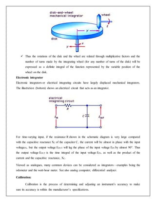
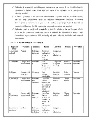
This document provides an overview of instrumentation and measurement concepts. It discusses that instrumentation deals with measurement techniques and measuring devices. Measurement involves comparing an unknown quantity to a standard.
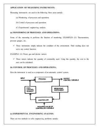
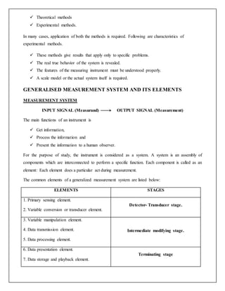
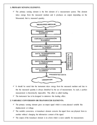
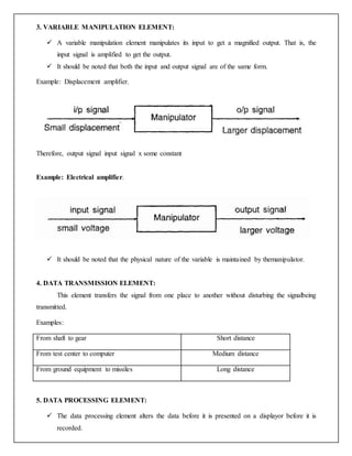
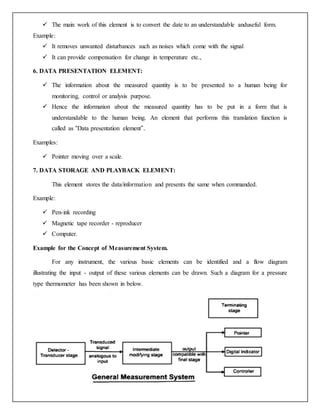
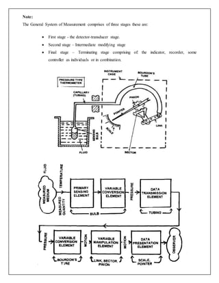
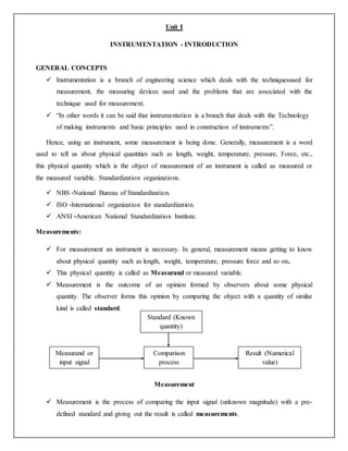
A measurement system consists of various elements including a primary sensing element to detect the measured quantity, a transducer to convert it to another form, and elements for signal manipulation, transmission, processing, presentation and storage. Measurement methods can be direct, comparing the measured quantity directly to a standard, or indirect, using a measurement system with multiple elements. Measurements are used for process monitoring, control and experimental analysis.
![ The analogous signal is then processed and is sent to the end devices which present the result
of measurement.
“In short, in indirect comparison method, the input signal is converted to some other form
and then it is compared with the standard”.
Methods of measurement can also be classified as
a. Primary measurement
b. Secondary measurement
c. Tertiary measurement
Primary Measurement
Only subjective information is provided in this method.
Example:
One vessel is cooler than the other.
One rod is longer than the other.
These measurements are made by direct observation. They do not involve any
translation of information.
Secondary Measurement
In this method, the output result is obtained by one translation.
Example:
Convertion of Measurand into length which is shown below. Bellows, bourdon’s pressure
gauge.
Pressure length
Primary signal secondary signal
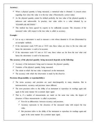
Tertiary Measurement:
In this method, the output result is obtained by two translations.
Example:
Electric tachometer. The input is converted to voltage then this voltage is converted to length.
Speed voltage length
Primary signalsecondary signal Tertiary signal
Measurand or
input
Translation Measured value or
output
Voltmeter
[second
translation]
Output or
measured
value
Tachometer
(translation)
Input or
measurand](https://image.slidesharecdn.com/uniti-200706101558/85/Unit-i-3-320.jpg)