Downloaded 322 times

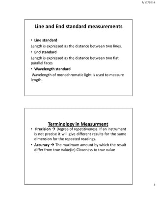
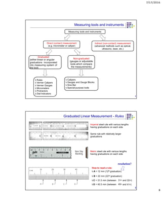

This document discusses measurement standards and metrology. It defines metrology as the science of measurement and describes standards as rules universally accepted for measuring quantity, weight, extent, value or quality. It then discusses different types of measurement standards including line standards, end standards and wavelength standards. The document also covers terminology related to measurements including accuracy, precision, sensitivity, resolution, range and stability. It describes the differences between repeatability and reproducibility in measurement systems. Finally, it categorizes measuring instruments and discusses sources of errors in measurements.


