Download as PDF, PPTX


![Toolpaths Manager
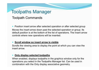
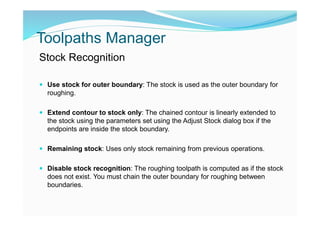
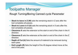
Lathe Point Toolpath
Use the Lathe Point Toolpath dialog box to create or edit a lathe point
toolpath. When you start the toolpath, you are prompted to select the
first point to which the tool will rapid from the home position. For each
point, first choose the motion mode, and then click the desired location
in the graphics window. Press [Esc] when you have finished selecting
points. The Toolpath parameters tab, where you can select tool,
coolant, stock, and other toolpath options, displays.
The dialog box contains the following options:
Specifies the move type, either Rapid, Rapid break, or Feed rate.](https://image.slidesharecdn.com/mastercamlathetutotialex-190627042632/85/Mastercam-lathe-tutotial-67-320.jpg)

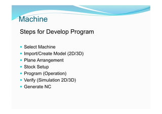
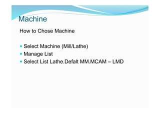
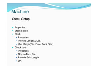
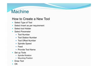
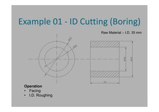
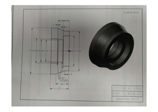
This document provides instructions for programming a lathe using Mastercam Lathe. It describes the basic steps for developing a program which include selecting the machine, importing or creating a 2D/3D model, setting up the stock, creating the program operations, verifying with simulation, and generating NC code. It also provides details on how to set up the stock, create and manage tools, and configure parameters for various lathe operations like facing and rough turning.