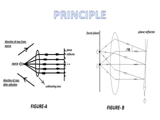
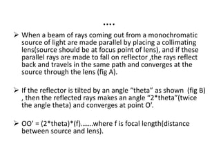
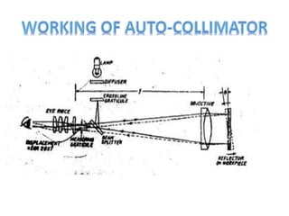
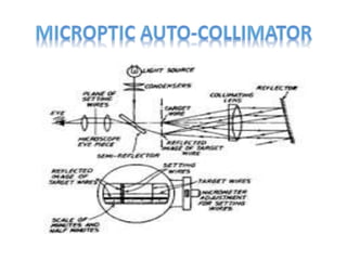
Auto-collimator is an optical instrument used
for the measurement of small angular
differences.
For small angular measurements it provides a
very sensitive and accurate approach.
It is essentially an infinity telescope and a
collimator combined into one instrument.
….
 When a beam of rays coming out from a monochromatic
source of light are made parallel by placing a collimating
lens(source should be at focus point of lens), and if these
parallel rays are made to fall on reflector ,the rays reflect
back and travels in the same path and converges at the
source through the lens (fig A).
 If the reflector is tilted by an angle “theta” as shown (fig B)
, then the reflected rays makes an angle “2*theta”(twice
the angle theta) and converges at point O’.
 OO’ = (2*theta)*(f)…….where f is focal length(distance
between source and lens).
….
• A cross line target graticule is positioned at the focal plane
of telescope objective. when the target graticule is
illuminated rays of light diverging from the intersection
point reach the objective via beam splitter and are
projected from objective as parallel . In this mode the
optical system works as collimator.
• A flat reflector placed in front of objective and normal to
the optical axis reflects parallel light back along their
original paths. They are then brought to focus in the plane
of target graticule and exactly coincident with its
intersection. A proportion of the returned light passes
straight through the beam splitter and the return image of
the target crossline is therefore visible through the
eyepiece thus operating as telescope focussed at infinity.
…
• If the reflector is tilted for an angle, the reflected rays
reflect twice the angle of tilt and are brought to focus in the
plane of the target graticule but linearly displaced from the
actual target by 2*(angle of tilt)*focal length.
• The linear displacement of the graticule image is measured
by an eyepiece graticule , optical micrometer or electronic
detector system , scaled directly in angular units.
• Auto-collimator responds only to reflector tilt.
• Focal length and the effective aperture are the factors
determines the basic sensitivity and angular measuring
range.
I. Photoelectric microptic auto-collimator
Micrometer adjustment is provided for setting ,but
coincidence of setting graticule and target image is
detected photo-electrically and shows null reading.
ii. Automatic position sensing auto-collimator
Angular displacement of the reflector is displayed on a
digital readout, eliminating any micrometer reading for
measuring . It is used for cramped positions.
iii. Microptic auto-collimator
In this a pair of target wires take place of the point light
source as it is not convenient to visualise the reflected
image of a point and then to measure the distance
precisely
Measurement of straightness and flatness.
Precise angular indexing in conjuction with
polygons.
Comparative measurement using master
angles.
Assessment of squareness and parallelism of
components.
Measurement of small linear dimensions.
 Levelling base
It supports the autocollimator and enables it to be levelled to bring its
axis parallel to the surface being measured.
 Surface plate stand
A multi purpose stand of heavy duty construction for general bench use,
comprising ground cast iron surface plate , column and bracket.
 Steel reflector
A reflector must be regraded as an integral part of any auto-collimator
system.
 Mounted glass corner reflector
This is used in conjuction with a reflector carriage and mounted reflector
for calibrating a surface plate.
 Steel cube reflector
It can be used as a general purpose reflector and for providing a 90
degrees angle standard in three planes and for checking perpendiculars.

Auto-collimator

  • 2.
    Auto-collimator is anoptical instrument used for the measurement of small angular differences. For small angular measurements it provides a very sensitive and accurate approach. It is essentially an infinity telescope and a collimator combined into one instrument.
  • 4.
    ….  When abeam of rays coming out from a monochromatic source of light are made parallel by placing a collimating lens(source should be at focus point of lens), and if these parallel rays are made to fall on reflector ,the rays reflect back and travels in the same path and converges at the source through the lens (fig A).  If the reflector is tilted by an angle “theta” as shown (fig B) , then the reflected rays makes an angle “2*theta”(twice the angle theta) and converges at point O’.  OO’ = (2*theta)*(f)…….where f is focal length(distance between source and lens).
  • 6.
    …. • A crossline target graticule is positioned at the focal plane of telescope objective. when the target graticule is illuminated rays of light diverging from the intersection point reach the objective via beam splitter and are projected from objective as parallel . In this mode the optical system works as collimator. • A flat reflector placed in front of objective and normal to the optical axis reflects parallel light back along their original paths. They are then brought to focus in the plane of target graticule and exactly coincident with its intersection. A proportion of the returned light passes straight through the beam splitter and the return image of the target crossline is therefore visible through the eyepiece thus operating as telescope focussed at infinity.
  • 7.
    … • If thereflector is tilted for an angle, the reflected rays reflect twice the angle of tilt and are brought to focus in the plane of the target graticule but linearly displaced from the actual target by 2*(angle of tilt)*focal length. • The linear displacement of the graticule image is measured by an eyepiece graticule , optical micrometer or electronic detector system , scaled directly in angular units. • Auto-collimator responds only to reflector tilt. • Focal length and the effective aperture are the factors determines the basic sensitivity and angular measuring range.
  • 8.
    I. Photoelectric micropticauto-collimator Micrometer adjustment is provided for setting ,but coincidence of setting graticule and target image is detected photo-electrically and shows null reading. ii. Automatic position sensing auto-collimator Angular displacement of the reflector is displayed on a digital readout, eliminating any micrometer reading for measuring . It is used for cramped positions. iii. Microptic auto-collimator In this a pair of target wires take place of the point light source as it is not convenient to visualise the reflected image of a point and then to measure the distance precisely
  • 9.
    Measurement of straightnessand flatness. Precise angular indexing in conjuction with polygons. Comparative measurement using master angles. Assessment of squareness and parallelism of components. Measurement of small linear dimensions.
  • 12.
     Levelling base Itsupports the autocollimator and enables it to be levelled to bring its axis parallel to the surface being measured.  Surface plate stand A multi purpose stand of heavy duty construction for general bench use, comprising ground cast iron surface plate , column and bracket.  Steel reflector A reflector must be regraded as an integral part of any auto-collimator system.  Mounted glass corner reflector This is used in conjuction with a reflector carriage and mounted reflector for calibrating a surface plate.  Steel cube reflector It can be used as a general purpose reflector and for providing a 90 degrees angle standard in three planes and for checking perpendiculars.