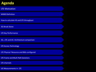
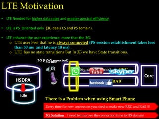
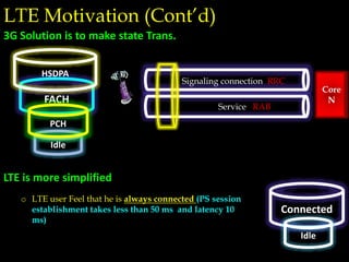
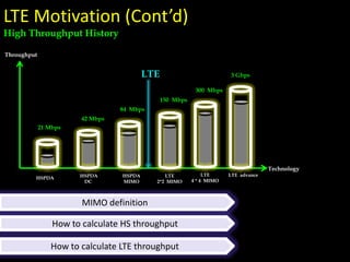
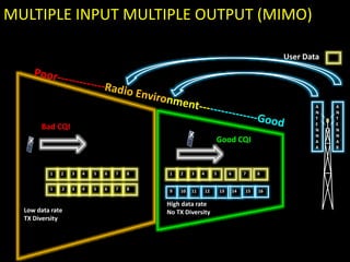
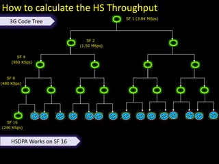
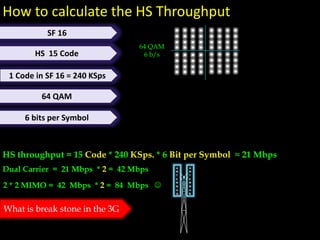
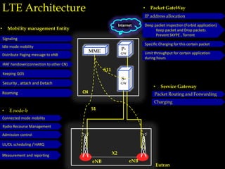
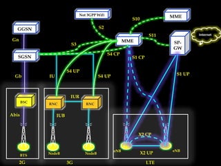
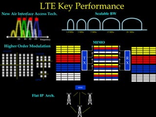
Radio Frequency Team
Etisalat
Cairo Feb-2014
Mostafa Adawy
LTE Vs. 3G
Work Shop
Agenda
LTE Motivation
MIMO Definition
How to calculate HS and LTE throughput
3G Break Stone
LTE Key Performance
3G , LTE and 2G Architecture comparison
LTE Access Technology
LTE Physical Resource and BWs configured
LTE Frame and Multi Path Solutions
LTE channels
UE Measurements in LTE
LTE Motivation
LTE Motivation
• LTE Needed for higher data rates and greater spectral efficiency.
• LTE is PS Oriented only (3G deals CS and PS domain).
• LTE enhance the user experience more than the 3G.
o LTE user Feel that he is always connected (PS session establishment takes less
than 50 ms and latency 10 ms)
o LTE has no state transitions But In 3G we have State transitions.
Core
Signaling connection RRC
Service RAB
3G (HS Connected)3G Idle
There is a Problem when using Smart Phone
HSDPA
Idle
Every time for new connection you need to make new RRC and RAB 
3G Solution : I need to Improve the connection time to HS domain
Connected
Idle
Idle
FACH
HSDPA
LTE Motivation (Cont’d)
Core
N
Signaling connection RRC
Service RAB
3G Solution is to make state Trans.
PCH
LTE is more simplified
o LTE user Feel that he is always connected (PS session
establishment takes less than 50 ms and latency 10
ms)
HSPDA HSPDA
DC
HSPDA
MIMO
LTE
2*2 MIMO
LTE advance
Throughput
21 Mbps
42 Mbps
84 Mbps
150 Mbps
3 Gbps
LTE
4 * 4 MIMO
300 Mbps
LTE Motivation (Cont’d)
Technology
LTE
MIMO definition
How to calculate LTE throughput
How to calculate HS throughput
High Throughput History
User Data
2 3 5 6 7 841
Bad CQI
Good CQI
Low data rate
TX Diversity
10 11 13 14 15129
2 3 5 6 7 841
3 5 6 7 841 2 16
A
N
T
E
N
N
A
A
A
N
T
E
N
N
A
B
High data rate
No TX Diversity
MULTIPLE INPUT MULTIPLE OUTPUT (MIMO)
SF 8
(480 KSps)
SF 2
(1.92 MSps)
SF 1 (3.84 MSps)
SF 4
(960 KSps)
How to calculate the HS Throughput
3G Code Tree
SF 16
(240 KSps)
HSDPA Works on SF 16
How to calculate the HS Throughput
64 QAM
6 b/s
SF 16
HS 15 Code
1 Code in SF 16 = 240 KSps
64 QAM
6 bits per Symbol
HS throughput = 15 Code * 240 KSps. * 6 Bit per Symbol ≈ 21 Mbps
Dual Carrier = 21 Mbps * 2 = 42 Mbps
2 * 2 MIMO = 42 Mbps * 2 = 84 Mbps 
What is break stone in the 3G
SF 8
480 Kbps
SF 2
SF 1
SF 4
SF 16
1 R99
User
1 R99
User
R99 is Break Stone
R99 (killer ) one user R99 will impact the HS (code absorbers)
LTE vs. HSPA+
Advantage of LTE over HSPA+
Advantage of HSPA+ over LTE
High Data Rates
Better spectrum efficiency (bits per Hz)
Low latency
Saving CAPEX Simple architecture (no RNCs and BSCs)
Lower Cost in managing and maintaining the network (less hardware)
LTE use SON (Self Organizing Network)
• Automatic neighbor Relation addition
• Self configuring Node-b
HSPA+ is already commercial
LTE is complete new network (HSPA+ is less investment)
LTE UE is expensive
3G , LTE and 2G
Architecture & interfaces
IUR
GGSN MSC
SGSN
RNCRNC eNB
MGW
CN
eNB
MME SP GWCN
WCDMA LTE
S1 S1
Signaling Data
Node-B
PS + CS PS Domain Only
No RNCs (function is done by eNB) e.g.. call admission
CN is directly connected to access part
LTE is packet oriented ( Over IP ) even Voice
For Voice now we use fall back to 3G
X2
eNB eNB
MME
S-
GW
Internet
P-
GW
Eutran
• Mobility management Entity
S11
S1
LTE Architecture
Connected mode mobility
Radio Recourse Management
Admission control
UL/DL scheduling / HARQ
Measurement and reporting
CN
Signaling
Idle mode mobility
Distribute Paging message to eNB
IRAT handover(connection to other CN)
Keeping QOS
Security , attach and Detach
Roaming
• E node-b
Packet Routing and Forwarding
Charging
• Service Gateway
Limit throughput for certain application
during hours
IP address allocation
Deep packet inspection (Forbid application)
Keep packet and Drop packets
Prevent SKYPE , Torrent
Specific Charging for this certain packet
• Packet GateWay
BTS
BSC
NodeB NodeB
RNC RNC
eNB eNB
SP-
GW
SGSN
GGSN
MME
S11
X2 UP
S1 CP
S1 UP
S3
MME
S10
Not 3GPP Wifi
S2
IUR
S4 UP
Abis
Gb
Gn
S4 CP
IUB
IU
X2 CP
Internet
2G 3G LTE
S4 UP
LTE Key Performance
LTE Key Performance
Higher Order Modulation
64 QAM
16 QAM
QPSK
1.4 MHz 3 MHz 5 MHz 15 MHz 20 MHz
Scalable BW
Flat IP Arch.
T
X
R
X
F0 F2 F3 FrequencyF1
MME
New Air Interface Access Tech.
MIMO
LTE Access Technology
Time
Freq.
Time
Time
Freq.
Freq.
FDMA FDMA / TDMA
Power
WCDMA
LTE access Technique
In LTE
Lets Remember
Ts
1/Ts 2/Ts 3/Ts 4/Ts 5/Ts-1/Ts-3/Ts -2/Ts-4/Ts
Time
Frequency
S(t)
S(f)
Time Domain
Frequency domain
 I need the peak
LTE access Technique (Cont’d)
Lets Remember
1/Ts 2/Ts 3/Ts 4/Ts 5/Ts-1/Ts-3/Ts -2/Ts-4/Ts Frequency
Frequency division multiplexing (FDM)
• Case 1 (FDM ): Allocation for the pulses on Freq. Band
Peak of one is Zero of the others
F1 F3 F4
Frequency
F2
• Case 2 :
o Pulse Shaping (Time stretch)
o Choose the correct Frequency
Case 2 (OFDM)
BW is less than case 1
Case 2 is more BW efficient
I can chose frequency so that the peak of one is at the Zeros of the others
F1 F3 F4F2 F5 F7 F8F6
Time
Freq.
Sub Carrier BW = 15 KHz
Symbol
LTE Access Technique (OFDM)
LTE Downlink DL
Time
Freq.
LTE Use OFDM in DL.
Subcarrier BM is 15 KHz.
Number of Subcarrier depend on the BW used.
Orthogonal (At sampling point all other carriers are zeros).
LTE Radio access Uplink UL
Single Carrier
Single
Carrier
Single Carrier
LTE use OFDM in UL (Single Carrier OFDM)
Subcarrier BM is 15 KHz
Why SC Carrier in UL
o To avoid Peak to Average Power Ratio PAPR
o Any PA should be operated in the linear region other wise you will have
distortion in the O/P signal
Linear Region
SC 1
SC 2
SC 3
Spike Of Power
Peaks Of Power
Peaks Of Power (PAPR)
For DL ( OK )
E-NB has expensive PA sufficient linear region can detail with this peaks
For UL (Not OK)
UE is cheap PA can’t detail with this peaks
FFT
Single Carrier
For UL Convert Subcarriers to Single Carrier (to Avoid PAPR)
Freq.
Time
LTE Radio access Uplink UL
SC FDMA
LTE Physical Resource
LTE Radio Physical Resource
Resource Element (RE)
Freq.
Time
LTE Time Slot
0.5 ms
7 Symbols
1 Sub Carrier( 15 kHz)
LTE Symbol (Contain # of bits)
Depend on Modulation
1 Recourse Element
1 subcarrier and 1 Symbol
LTE Radio Physical Resource
Resource Block (RB)
Freq.
Time
LTE Time Slot
0.5 ms
7 Symbol
1 Recourse block ( RB )
o 12 Sub Carrier (15 KHz) * 7 Symbols
o 84 Recourse Element
o RB Basic Unit for Transmission of information
12 Sub Carrier
LTE Radio Physical Resource
Resource Block (RB)
Freq.
Time
Time Slot
7 Symbols
0.5 ms
12 Sub Carrier
Symbol
One Recourse block
84 Recourse element
LTE Radio Physical Resource
Resource Block (RB)
Freq.
Time
Time Slot
7 Symbols
0.5 ms
12 Sub Carrier
Symbol
o During the DT if you need to check the throughput
You check how many RBs assigned for this user #RB increase . Throughput incre.
You don’t check how many subcarriers and you don’t check how many symbols
Even in counter you check the resource block consumption
Freq.
Time
Time Slot
7 Symbols
0.5 ms
Time Slot
7 Symbols
0.5 ms
LTE Scheduler
• LTE Scheduler
• 1 User is scheduled every TTI ( 1ms )
• Every Schedule instance we have 2 consecutive RBs per user
• Called Scheduled block
LTE Allowed Bandwidths BW
1.4 MHz 3 MHz 5 MHz 15 MHz 20 MHz10 MHz
3GPP define exact BWs used for LTE (fixed) no 18 MHz
You Don’t have to buy new band but you can make band reframing
The more BW you have
o Better throughput
o More Resource blocks
Band Width MHz Number of RB s
1.4 MHz 6
3.0 MHz 15
5.0 MHz 25
10.0 MHz 50
15.0 MHz 75
20.0 MHz 100
LTE Allowed Bandwidths BW (Cont’d)
3GPP
The more BW you have
o Better throughput
o More Resources you have (More Resource block)
# 1
Time Slot
0.5 ms
# 2 TS # 20
LTE One Radio Frame 10 ms
One Sub Frame
1 ms
1 7
7 Symbols
LTE Frame
Bits Bits Bits Bits Bits BitsBits
64 QAM
6 b/s
16 QAM
4 b/s
QPSK
2 b/s
Number of bits per Symbol depend on Modulation technique
# bits = 100 RB * 7 symbols * 12 Subcarrier * 2 (1SB =2RB)*6 bit (64 QAM) * 4 (MIMO)
Throughput RATE = 7 symbols * 12 Subcarrier * 2 (1SB =2RB) *100 * 6 bit (64 QAM) * 4 (MIMO)
1 ms
BW = 20 MHZ
Modulation 64 QAM
MIMO 4*4
Calculate the max. physical throughput in LTE where
BW =20 MHz  100 RB
1 RB  7 symbols * 12 Subcarrier
SB = 2 RB (1 ms )
1 Symbol  6 bits (64 QAM)
1 User is scheduled every 1 ms
Throughput RATE = 380 Mbps
LTE Multi Path solution
Channel Paths
0
1
2
3
Path 1
ISI Impact is Very High
Pulse Stretch
ISI Impact is not So High
Lets Remember
CP A
Slot A (7 Symbols)
Cyclic Prefix (Inter Symbol interference cure)
Slot A (7 Symbols) Slot B (7 Symbols) Slot C (7 Symbols)
Path 1
Path 2
ISI
Cyclic Prefix Slot T=0
Total Transmitted
Slot A Slot B Slot C
Path 1
Path 2
CP A
CP A
CP B
CP B
CP C
CP C
ISI
ISI ISI
LTE Radio Channels
LTE Channels
Physical Channel
Transport Channel
LOGICAL CHANNELS
Air Interface
Logical Channels
Transport Channels
Physical channels
LTE Channels
What Type of data I will sent
It may carry control data or carry user traffic
How do I sent the information (the manner in which the data will be Transferred)
Weather the data is protected from errors
Size of the data packets
Define the way I sent the data
What is modulation
What is BW we will use
Logical Channels Transport Channels Physical Channels
BCCH
BCH
PBCH
MTCH
MCCH
PMCH
MCH
DTCH
DCCH
DL-SCH PDSCH -- Data
PDCCH
PCFICH
PHICH
Broadcast channel
Carry cell
information
Multicast channel
advertising
Dedicated Traffic
and control channel
“User Data”
Physical downlink control channel
o Scheduler use this channel
o Which user will receive data
o UE listen to this channel
o Ok I have data for me
o # of RBs
o Type of Modulation
o Power Control commands
Physical control format indic.
channel
o Format of the PDCCH
o Data
o Power Control
Physical hybrid ARQ indication Ch.
o ACK/NACK
LTE DL Channels
P-SCH
S-SCH
RS
Generated by E-Node-B
used to identify the Cell
LTE UL Channels
Logical ChannelsTransport ChannelsPhysical Channels
PRACH
RACH
CCCH
Physical Random
access channel
Call Setup
PUSCH UL-SCH
DTCH
Physical UL Shared
channel
Data in UL
DCCH
PUCCH
Physical UL control channel
o Ack/NACK
o UL Schedule request
How to identify the enode-B (LTE Cell)
• In 3G we Define the Cell using Scrambling Code (SC)
• In LTE we have Reference Signal (RS) used to define the Cell
• We have 504 different Reference Signals (RS) used to define the Cells
• S-SCH and P-SCH are used to create the (RS)
We have to be synchronized with RS to be able to demodulate the data
P-SCH (3 orthogonal Sequence )
S-SCH (168 Random Sequence)
504 RSs ( 3 orth. * 168 Random )
504 PCI
504 Physical Cell Identity
S-SCH (168 Random Seq. ) P-SCH (3 orthogonal Seq.)
S-SCH -0 P-SCH-0 , P-SCH-1 , P-SCH-2
S-SCH -1 P-SCH-0 , P-SCH-1 , P-SCH-2
S-SCH -3 P-SCH-0 , P-SCH-1 , P-SCH-2
S-SCH -4 P-SCH-0 , P-SCH-1 , P-SCH-2
--------------- -----------
----------------- -----------
--------------------- ----------
-------------------- ----------------
------------------------ -------------
------------------ ------------
-------------------- -------------
---------------- ---------------
---------------- --------------
S-SCH -167 P-SCH-0 , P-SCH-1 , P-SCH-2
• 504 PCI could be reused for LTE network
• PCI Planning Principles
PCI 13
PCI 14PCI 12
PCI 15 PCI 18
PCI 16
PCI 17
PCI 13
PCI 12
PCI 14
PCI 13
PCI 17
PCI 11
PCI 15
PCI 17
PCI 14
PCI 13
PCI 14
PCI 17
PCI 14
PCI 18
PCI 12
PCI 15
PCI 14
PCI 15
Distance between Same PCI
We have 504 so it is easy to avoid this
Same as SC in 3G
Collision Free Confusion Free
Cell 1 Cell 2
PCI -168 PCI 168
PCI -168
PCI 167
PCI -168
Neigh-1 Neigh-2
PCI Planning Principles (Cont’d)
Near Cells should be with different PCI
Synchronized with RS to be able to read
the information
Cells in the Neighbor list should be
different PCI
# 0 #1
1 Sub Frame
1 ms
LTE One Radio Frame 10 ms
0 1 2 3 4 5 6 0 1 2 3 4 5 6
Time Slot 0.5 ms Time Slot 0.5 ms
# 2 # 3 # 4 # 5 # 6 # 7 # 8 # 9
Freq.
Time.
SystemBW
0 1 2 3 4 5 6 0 1 2 3 4 5 6
Time Slot 0.5 ms Time Slot 0.5 ms
S-SCH P-SCH S-SCH P-SCH
• Information of the Synchronization in Sub frame 0 and 5 (every 5 ms)
P-SCH (3 orthogonal Sequence )
S-SCH (168 Random Sequence)
504 RSs ( 3 orth. * 168 Random )
504 PCI
504 Physical Cell Identity
Freq.
Time.
BWUsed
ContainsSubCarriers
• One Resource element : 1 subcarrier and 1 Symbol
• One RB : 12 Sub Carrier and 7 Symbol (84 Resource element)
RB
• RS (Reference Signal) • PDCCH (Schedule use this Ch.)
• PSCH/SSCH • PDSCH (user data)
• PBCH
Freq.
Time.
0 1 2 3 4 5 6 0 1 2 3 4 5 6 0 1 2 3 4 5 6
Sub Frame
Time Slot 0.5 ms Time Slot 0.5 ms
• RS (Reference Signal) • PDCCH (Schedule use this Ch.)
• PSCH/SSCH
• PDSCH• PBCH
10 Sub Frames = 1 Frame (10 ms)
Every time slot we have RS.
We need it in order to decode the information in the slot.
We have to be synchronized with RS to be able to
demodulate the data in each slot
Using MIMO
A
N
T
E
N
N
A
A
A
N
T
E
N
N
A
B
Freq.
Time.
BWUsed
ContainsSubCarriers
R
R
R
R
R
R
0 1 2 3 4 5 6 0 1 2 3 4 5 6
Sub Frame
Time Slot 0.5 ms Time Slot 0.5 ms
Sub Frame
0 1 2 3 4 5 6 0 1 2 3 4 5 6
Time Slot 0.5 ms Time Slot 0.5 ms
Time.
R
R
R
R
R
R
R
R
R
R
R
R
R
R
R
R
R
R
R
R
R
R
R
R
R
R
R
R
R
R
R
R
R
R
R
R
R
R
R
R
R
R
R
R
R
R
R
R
R
R
R
R
R
R
Same Time and Same Sub Carrier
So you will have interference (SINR)
You need to Synch. With the RS to read the information in Frame,
so if you are not able to get the RS you cant decode any thing
A
N
T
E
N
N
A
A
A
N
T
E
N
N
A
B
Freq.
Time.
BWUsed
ContainsSubCarriers
R
R
R
0 1 2 3 4 5 6 0 1 2 3 4 5 6
Sub Frame
Time Slot 0.5 ms Time Slot 0.5 ms
Sub Frame
0 1 2 3 4 5 6 0 1 2 3 4 5 6
Time Slot 0.5 ms Time Slot 0.5 ms
Time.
R
R
R
R
R
R
R
R
R
R
R
R
R
R
R
R
R
R
R
R
R
R
R
R
R
R
R
At the same time and Freq. when one antenna transmit RS the other one will not Transmit to avoid
interference
So using MIMO you are increasing the throughput but wasting Resource elements
LTE UE Measurements
• What UE measure in the DL ?
• RSRP ( Reference Signal Received Power ) for a certain Cell
o Measurements of all RS in all BW as average
o Ranges -40 to -125 dBm
o RSRP is used to measure the coverage
Freq.
Time.
BWUsedContainsSubCarriers
R
R
R
R
R
R
0 1 2 3 4 5 6 0 1 2 3 4 5 6
Sub Frame
LTE Measurements
• RSSI ( Reference Signal Strength Indicator)
o Is the energy in the complete BW
o Not the RS only but all the Power and it include the thermal noise also
o Neighbor Site interference
LTE Measurements
• RSRQ ( Reference Signal Received Quality )
o Similar to EcNo in 3G (we use it to measure the interference)
o Ranges -3 to -20 dB
o RSRQ = n * RSRP (one cell) / RSSI (Power in whole BW for all )
• n is the number of RBs in all the BW
LTE Measurements
• RSRP and RSRQ are used for handovers and cell selection and Reselection
• Most operators are now use the RSRP for Mobility instead of RSRQ
o change very Fast
o Traffic Dependent due to the RSSI
o Its is sense of the cell not the User
RSRQ
-
-
-
-
-
-
RSRQ low
RSSI High
LTE Measurements
• LTE SINR (Signal interference Noise Ratio)
o Is calculated by the UE (no 3GPP but depend on the vendor)
 S ( Power of the RS and Data)
 I ( Interference Signals form other cells)
 N ( back ground noise and Rx Noise coefficient)
SINR
‫وعظيم‬ ‫وجهه‬ ‫لجالل‬ ‫ينبغي‬ ‫كما‬ ‫هلل‬ ‫الحمد‬‫سلطانه‬
‫شكرا‬

LTE Vs. 3G

  • 1.
    Radio Frequency Team Etisalat CairoFeb-2014 Mostafa Adawy LTE Vs. 3G
  • 2.
  • 3.
    Agenda LTE Motivation MIMO Definition Howto calculate HS and LTE throughput 3G Break Stone LTE Key Performance 3G , LTE and 2G Architecture comparison LTE Access Technology LTE Physical Resource and BWs configured LTE Frame and Multi Path Solutions LTE channels UE Measurements in LTE
  • 4.
  • 5.
    LTE Motivation • LTENeeded for higher data rates and greater spectral efficiency. • LTE is PS Oriented only (3G deals CS and PS domain). • LTE enhance the user experience more than the 3G. o LTE user Feel that he is always connected (PS session establishment takes less than 50 ms and latency 10 ms) o LTE has no state transitions But In 3G we have State transitions. Core Signaling connection RRC Service RAB 3G (HS Connected)3G Idle There is a Problem when using Smart Phone HSDPA Idle Every time for new connection you need to make new RRC and RAB  3G Solution : I need to Improve the connection time to HS domain
  • 6.
    Connected Idle Idle FACH HSDPA LTE Motivation (Cont’d) Core N Signalingconnection RRC Service RAB 3G Solution is to make state Trans. PCH LTE is more simplified o LTE user Feel that he is always connected (PS session establishment takes less than 50 ms and latency 10 ms)
  • 7.
    HSPDA HSPDA DC HSPDA MIMO LTE 2*2 MIMO LTEadvance Throughput 21 Mbps 42 Mbps 84 Mbps 150 Mbps 3 Gbps LTE 4 * 4 MIMO 300 Mbps LTE Motivation (Cont’d) Technology LTE MIMO definition How to calculate LTE throughput How to calculate HS throughput High Throughput History
  • 8.
    User Data 2 35 6 7 841 Bad CQI Good CQI Low data rate TX Diversity 10 11 13 14 15129 2 3 5 6 7 841 3 5 6 7 841 2 16 A N T E N N A A A N T E N N A B High data rate No TX Diversity MULTIPLE INPUT MULTIPLE OUTPUT (MIMO)
  • 9.
    SF 8 (480 KSps) SF2 (1.92 MSps) SF 1 (3.84 MSps) SF 4 (960 KSps) How to calculate the HS Throughput 3G Code Tree SF 16 (240 KSps) HSDPA Works on SF 16
  • 10.
    How to calculatethe HS Throughput 64 QAM 6 b/s SF 16 HS 15 Code 1 Code in SF 16 = 240 KSps 64 QAM 6 bits per Symbol HS throughput = 15 Code * 240 KSps. * 6 Bit per Symbol ≈ 21 Mbps Dual Carrier = 21 Mbps * 2 = 42 Mbps 2 * 2 MIMO = 42 Mbps * 2 = 84 Mbps  What is break stone in the 3G
  • 11.
    SF 8 480 Kbps SF2 SF 1 SF 4 SF 16 1 R99 User 1 R99 User R99 is Break Stone R99 (killer ) one user R99 will impact the HS (code absorbers)
  • 12.
    LTE vs. HSPA+ Advantageof LTE over HSPA+ Advantage of HSPA+ over LTE High Data Rates Better spectrum efficiency (bits per Hz) Low latency Saving CAPEX Simple architecture (no RNCs and BSCs) Lower Cost in managing and maintaining the network (less hardware) LTE use SON (Self Organizing Network) • Automatic neighbor Relation addition • Self configuring Node-b HSPA+ is already commercial LTE is complete new network (HSPA+ is less investment) LTE UE is expensive
  • 13.
    3G , LTEand 2G Architecture & interfaces
  • 14.
    IUR GGSN MSC SGSN RNCRNC eNB MGW CN eNB MMESP GWCN WCDMA LTE S1 S1 Signaling Data Node-B PS + CS PS Domain Only No RNCs (function is done by eNB) e.g.. call admission CN is directly connected to access part LTE is packet oriented ( Over IP ) even Voice For Voice now we use fall back to 3G
  • 15.
    X2 eNB eNB MME S- GW Internet P- GW Eutran • Mobilitymanagement Entity S11 S1 LTE Architecture Connected mode mobility Radio Recourse Management Admission control UL/DL scheduling / HARQ Measurement and reporting CN Signaling Idle mode mobility Distribute Paging message to eNB IRAT handover(connection to other CN) Keeping QOS Security , attach and Detach Roaming • E node-b Packet Routing and Forwarding Charging • Service Gateway Limit throughput for certain application during hours IP address allocation Deep packet inspection (Forbid application) Keep packet and Drop packets Prevent SKYPE , Torrent Specific Charging for this certain packet • Packet GateWay
  • 16.
    BTS BSC NodeB NodeB RNC RNC eNBeNB SP- GW SGSN GGSN MME S11 X2 UP S1 CP S1 UP S3 MME S10 Not 3GPP Wifi S2 IUR S4 UP Abis Gb Gn S4 CP IUB IU X2 CP Internet 2G 3G LTE S4 UP
  • 17.
  • 18.
    LTE Key Performance HigherOrder Modulation 64 QAM 16 QAM QPSK 1.4 MHz 3 MHz 5 MHz 15 MHz 20 MHz Scalable BW Flat IP Arch. T X R X F0 F2 F3 FrequencyF1 MME New Air Interface Access Tech. MIMO
  • 19.
  • 20.
    Time Freq. Time Time Freq. Freq. FDMA FDMA /TDMA Power WCDMA LTE access Technique
  • 21.
  • 22.
    Ts 1/Ts 2/Ts 3/Ts4/Ts 5/Ts-1/Ts-3/Ts -2/Ts-4/Ts Time Frequency S(t) S(f) Time Domain Frequency domain  I need the peak LTE access Technique (Cont’d) Lets Remember
  • 23.
    1/Ts 2/Ts 3/Ts4/Ts 5/Ts-1/Ts-3/Ts -2/Ts-4/Ts Frequency Frequency division multiplexing (FDM) • Case 1 (FDM ): Allocation for the pulses on Freq. Band Peak of one is Zero of the others F1 F3 F4 Frequency F2 • Case 2 : o Pulse Shaping (Time stretch) o Choose the correct Frequency Case 2 (OFDM) BW is less than case 1 Case 2 is more BW efficient I can chose frequency so that the peak of one is at the Zeros of the others
  • 24.
    F1 F3 F4F2F5 F7 F8F6 Time Freq. Sub Carrier BW = 15 KHz Symbol LTE Access Technique (OFDM)
  • 25.
    LTE Downlink DL Time Freq. LTEUse OFDM in DL. Subcarrier BM is 15 KHz. Number of Subcarrier depend on the BW used. Orthogonal (At sampling point all other carriers are zeros).
  • 26.
    LTE Radio accessUplink UL Single Carrier Single Carrier Single Carrier LTE use OFDM in UL (Single Carrier OFDM) Subcarrier BM is 15 KHz
  • 27.
    Why SC Carrierin UL o To avoid Peak to Average Power Ratio PAPR o Any PA should be operated in the linear region other wise you will have distortion in the O/P signal Linear Region
  • 28.
    SC 1 SC 2 SC3 Spike Of Power
  • 29.
    Peaks Of Power PeaksOf Power (PAPR) For DL ( OK ) E-NB has expensive PA sufficient linear region can detail with this peaks For UL (Not OK) UE is cheap PA can’t detail with this peaks FFT Single Carrier For UL Convert Subcarriers to Single Carrier (to Avoid PAPR)
  • 30.
    Freq. Time LTE Radio accessUplink UL SC FDMA
  • 31.
  • 32.
    LTE Radio PhysicalResource Resource Element (RE) Freq. Time LTE Time Slot 0.5 ms 7 Symbols 1 Sub Carrier( 15 kHz) LTE Symbol (Contain # of bits) Depend on Modulation 1 Recourse Element 1 subcarrier and 1 Symbol
  • 33.
    LTE Radio PhysicalResource Resource Block (RB) Freq. Time LTE Time Slot 0.5 ms 7 Symbol 1 Recourse block ( RB ) o 12 Sub Carrier (15 KHz) * 7 Symbols o 84 Recourse Element o RB Basic Unit for Transmission of information 12 Sub Carrier
  • 34.
    LTE Radio PhysicalResource Resource Block (RB) Freq. Time Time Slot 7 Symbols 0.5 ms 12 Sub Carrier Symbol One Recourse block 84 Recourse element
  • 35.
    LTE Radio PhysicalResource Resource Block (RB) Freq. Time Time Slot 7 Symbols 0.5 ms 12 Sub Carrier Symbol o During the DT if you need to check the throughput You check how many RBs assigned for this user #RB increase . Throughput incre. You don’t check how many subcarriers and you don’t check how many symbols Even in counter you check the resource block consumption
  • 36.
    Freq. Time Time Slot 7 Symbols 0.5ms Time Slot 7 Symbols 0.5 ms LTE Scheduler • LTE Scheduler • 1 User is scheduled every TTI ( 1ms ) • Every Schedule instance we have 2 consecutive RBs per user • Called Scheduled block
  • 37.
    LTE Allowed BandwidthsBW 1.4 MHz 3 MHz 5 MHz 15 MHz 20 MHz10 MHz 3GPP define exact BWs used for LTE (fixed) no 18 MHz You Don’t have to buy new band but you can make band reframing The more BW you have o Better throughput o More Resource blocks
  • 38.
    Band Width MHzNumber of RB s 1.4 MHz 6 3.0 MHz 15 5.0 MHz 25 10.0 MHz 50 15.0 MHz 75 20.0 MHz 100 LTE Allowed Bandwidths BW (Cont’d) 3GPP The more BW you have o Better throughput o More Resources you have (More Resource block)
  • 39.
    # 1 Time Slot 0.5ms # 2 TS # 20 LTE One Radio Frame 10 ms One Sub Frame 1 ms 1 7 7 Symbols LTE Frame Bits Bits Bits Bits Bits BitsBits 64 QAM 6 b/s 16 QAM 4 b/s QPSK 2 b/s Number of bits per Symbol depend on Modulation technique
  • 40.
    # bits =100 RB * 7 symbols * 12 Subcarrier * 2 (1SB =2RB)*6 bit (64 QAM) * 4 (MIMO) Throughput RATE = 7 symbols * 12 Subcarrier * 2 (1SB =2RB) *100 * 6 bit (64 QAM) * 4 (MIMO) 1 ms BW = 20 MHZ Modulation 64 QAM MIMO 4*4 Calculate the max. physical throughput in LTE where BW =20 MHz  100 RB 1 RB  7 symbols * 12 Subcarrier SB = 2 RB (1 ms ) 1 Symbol  6 bits (64 QAM) 1 User is scheduled every 1 ms Throughput RATE = 380 Mbps
  • 41.
  • 42.
    Channel Paths 0 1 2 3 Path 1 ISIImpact is Very High Pulse Stretch ISI Impact is not So High Lets Remember
  • 43.
    CP A Slot A(7 Symbols) Cyclic Prefix (Inter Symbol interference cure) Slot A (7 Symbols) Slot B (7 Symbols) Slot C (7 Symbols) Slot A (7 Symbols) Slot B (7 Symbols) Slot C (7 Symbols) Path 1 Path 2 ISI Cyclic Prefix Slot T=0 Total Transmitted Slot A Slot B Slot C Slot A Slot B Slot C Path 1 Path 2 CP A CP A CP B CP B CP C CP C ISI ISI ISI
  • 44.
  • 45.
    LTE Channels Physical Channel TransportChannel LOGICAL CHANNELS Air Interface
  • 46.
    Logical Channels Transport Channels Physicalchannels LTE Channels What Type of data I will sent It may carry control data or carry user traffic How do I sent the information (the manner in which the data will be Transferred) Weather the data is protected from errors Size of the data packets Define the way I sent the data What is modulation What is BW we will use
  • 47.
    Logical Channels TransportChannels Physical Channels BCCH BCH PBCH MTCH MCCH PMCH MCH DTCH DCCH DL-SCH PDSCH -- Data PDCCH PCFICH PHICH Broadcast channel Carry cell information Multicast channel advertising Dedicated Traffic and control channel “User Data” Physical downlink control channel o Scheduler use this channel o Which user will receive data o UE listen to this channel o Ok I have data for me o # of RBs o Type of Modulation o Power Control commands Physical control format indic. channel o Format of the PDCCH o Data o Power Control Physical hybrid ARQ indication Ch. o ACK/NACK LTE DL Channels P-SCH S-SCH RS Generated by E-Node-B used to identify the Cell
  • 48.
    LTE UL Channels LogicalChannelsTransport ChannelsPhysical Channels PRACH RACH CCCH Physical Random access channel Call Setup PUSCH UL-SCH DTCH Physical UL Shared channel Data in UL DCCH PUCCH Physical UL control channel o Ack/NACK o UL Schedule request
  • 49.
    How to identifythe enode-B (LTE Cell) • In 3G we Define the Cell using Scrambling Code (SC) • In LTE we have Reference Signal (RS) used to define the Cell • We have 504 different Reference Signals (RS) used to define the Cells • S-SCH and P-SCH are used to create the (RS) We have to be synchronized with RS to be able to demodulate the data P-SCH (3 orthogonal Sequence ) S-SCH (168 Random Sequence) 504 RSs ( 3 orth. * 168 Random ) 504 PCI 504 Physical Cell Identity
  • 50.
    S-SCH (168 RandomSeq. ) P-SCH (3 orthogonal Seq.) S-SCH -0 P-SCH-0 , P-SCH-1 , P-SCH-2 S-SCH -1 P-SCH-0 , P-SCH-1 , P-SCH-2 S-SCH -3 P-SCH-0 , P-SCH-1 , P-SCH-2 S-SCH -4 P-SCH-0 , P-SCH-1 , P-SCH-2 --------------- ----------- ----------------- ----------- --------------------- ---------- -------------------- ---------------- ------------------------ ------------- ------------------ ------------ -------------------- ------------- ---------------- --------------- ---------------- -------------- S-SCH -167 P-SCH-0 , P-SCH-1 , P-SCH-2 • 504 PCI could be reused for LTE network
  • 51.
    • PCI PlanningPrinciples PCI 13 PCI 14PCI 12 PCI 15 PCI 18 PCI 16 PCI 17 PCI 13 PCI 12 PCI 14 PCI 13 PCI 17 PCI 11 PCI 15 PCI 17 PCI 14 PCI 13 PCI 14 PCI 17 PCI 14 PCI 18 PCI 12 PCI 15 PCI 14 PCI 15 Distance between Same PCI We have 504 so it is easy to avoid this Same as SC in 3G
  • 52.
    Collision Free ConfusionFree Cell 1 Cell 2 PCI -168 PCI 168 PCI -168 PCI 167 PCI -168 Neigh-1 Neigh-2 PCI Planning Principles (Cont’d) Near Cells should be with different PCI Synchronized with RS to be able to read the information Cells in the Neighbor list should be different PCI
  • 53.
    # 0 #1 1Sub Frame 1 ms LTE One Radio Frame 10 ms 0 1 2 3 4 5 6 0 1 2 3 4 5 6 Time Slot 0.5 ms Time Slot 0.5 ms # 2 # 3 # 4 # 5 # 6 # 7 # 8 # 9 Freq. Time. SystemBW 0 1 2 3 4 5 6 0 1 2 3 4 5 6 Time Slot 0.5 ms Time Slot 0.5 ms S-SCH P-SCH S-SCH P-SCH • Information of the Synchronization in Sub frame 0 and 5 (every 5 ms) P-SCH (3 orthogonal Sequence ) S-SCH (168 Random Sequence) 504 RSs ( 3 orth. * 168 Random ) 504 PCI 504 Physical Cell Identity
  • 54.
    Freq. Time. BWUsed ContainsSubCarriers • One Resourceelement : 1 subcarrier and 1 Symbol • One RB : 12 Sub Carrier and 7 Symbol (84 Resource element) RB • RS (Reference Signal) • PDCCH (Schedule use this Ch.) • PSCH/SSCH • PDSCH (user data) • PBCH Freq. Time. 0 1 2 3 4 5 6 0 1 2 3 4 5 6 0 1 2 3 4 5 6 Sub Frame Time Slot 0.5 ms Time Slot 0.5 ms
  • 55.
    • RS (ReferenceSignal) • PDCCH (Schedule use this Ch.) • PSCH/SSCH • PDSCH• PBCH 10 Sub Frames = 1 Frame (10 ms) Every time slot we have RS. We need it in order to decode the information in the slot. We have to be synchronized with RS to be able to demodulate the data in each slot
  • 56.
  • 57.
    A N T E N N A A A N T E N N A B Freq. Time. BWUsed ContainsSubCarriers R R R R R R 0 1 23 4 5 6 0 1 2 3 4 5 6 Sub Frame Time Slot 0.5 ms Time Slot 0.5 ms Sub Frame 0 1 2 3 4 5 6 0 1 2 3 4 5 6 Time Slot 0.5 ms Time Slot 0.5 ms Time. R R R R R R R R R R R R R R R R R R R R R R R R R R R R R R R R R R R R R R R R R R R R R R R R R R R R R R Same Time and Same Sub Carrier So you will have interference (SINR) You need to Synch. With the RS to read the information in Frame, so if you are not able to get the RS you cant decode any thing
  • 58.
    A N T E N N A A A N T E N N A B Freq. Time. BWUsed ContainsSubCarriers R R R 0 1 23 4 5 6 0 1 2 3 4 5 6 Sub Frame Time Slot 0.5 ms Time Slot 0.5 ms Sub Frame 0 1 2 3 4 5 6 0 1 2 3 4 5 6 Time Slot 0.5 ms Time Slot 0.5 ms Time. R R R R R R R R R R R R R R R R R R R R R R R R R R R At the same time and Freq. when one antenna transmit RS the other one will not Transmit to avoid interference So using MIMO you are increasing the throughput but wasting Resource elements
  • 59.
    LTE UE Measurements •What UE measure in the DL ?
  • 60.
    • RSRP (Reference Signal Received Power ) for a certain Cell o Measurements of all RS in all BW as average o Ranges -40 to -125 dBm o RSRP is used to measure the coverage Freq. Time. BWUsedContainsSubCarriers R R R R R R 0 1 2 3 4 5 6 0 1 2 3 4 5 6 Sub Frame LTE Measurements
  • 61.
    • RSSI (Reference Signal Strength Indicator) o Is the energy in the complete BW o Not the RS only but all the Power and it include the thermal noise also o Neighbor Site interference LTE Measurements
  • 62.
    • RSRQ (Reference Signal Received Quality ) o Similar to EcNo in 3G (we use it to measure the interference) o Ranges -3 to -20 dB o RSRQ = n * RSRP (one cell) / RSSI (Power in whole BW for all ) • n is the number of RBs in all the BW LTE Measurements • RSRP and RSRQ are used for handovers and cell selection and Reselection • Most operators are now use the RSRP for Mobility instead of RSRQ o change very Fast o Traffic Dependent due to the RSSI o Its is sense of the cell not the User RSRQ - - - - - - RSRQ low RSSI High
  • 63.
    LTE Measurements • LTESINR (Signal interference Noise Ratio) o Is calculated by the UE (no 3GPP but depend on the vendor)  S ( Power of the RS and Data)  I ( Interference Signals form other cells)  N ( back ground noise and Rx Noise coefficient) SINR
  • 64.
    ‫وعظيم‬ ‫وجهه‬ ‫لجالل‬‫ينبغي‬ ‫كما‬ ‫هلل‬ ‫الحمد‬‫سلطانه‬ ‫شكرا‬

Editor's Notes

  • #48 PDCCH: Physical downlink control channel Scheduler use this channel Which user will receive data UE listen to this channel Ok I have data for me # of RBs Type of Modulation Power Control commands
  • #55 PDCCH: Physical downlink control channel Scheduler use this channel Which user will receive data UE listen to this channel Ok I have data for me # of RBs Type of Modulation Power Control commands