Downloaded 1,977 times


![Capacity of MIMO Channels
We assume M RX and N TX antennas. The capacity
in bits/sec/Hz of a MIMO channel under an
average transmitter power constraint is given by
C = log 2 [det(IM + p/N H H*) b/s/Hz]](https://image.slidesharecdn.com/prita-ppt22-121106130206-phpapp01/85/MIMO-ppt-2-2-7-320.jpg)
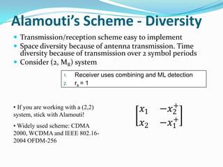
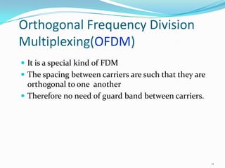
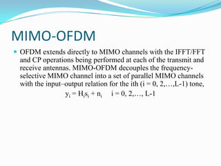
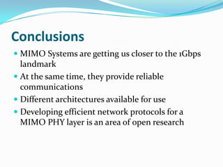


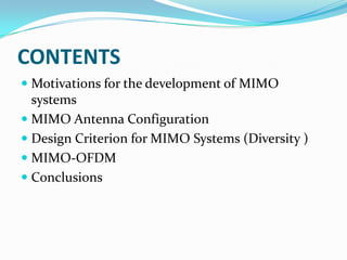
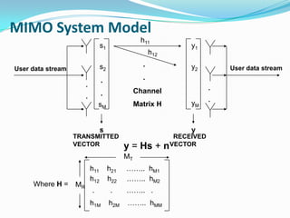
The document discusses MIMO (Multiple Input Multiple Output) systems. It motivates MIMO by explaining how system designers aim to achieve high data rates and quality while minimizing complexity, transmission power, and bandwidth. It describes MIMO antenna configurations including SISO and MIMO. MIMO systems use multiple transmit and receive antennas to achieve high capacity. The document outlines diversity as a design criterion for MIMO systems to achieve reliable reception. It also discusses Alamouti's space-time coding scheme and how MIMO can be combined with OFDM to further improve performance. In conclusions, MIMO brings us closer to gigabit speeds while also providing reliable communications.


![Mimo [new]](https://cdn.slidesharecdn.com/ss_thumbnails/mimonew-150914045107-lva1-app6892-thumbnail.jpg?width=640&height=640&fit=bounds)


![[Year 2012-13] Mimo technology](https://cdn.slidesharecdn.com/ss_thumbnails/mimotechnology-180701101303-thumbnail.jpg?width=640&height=640&fit=bounds)


