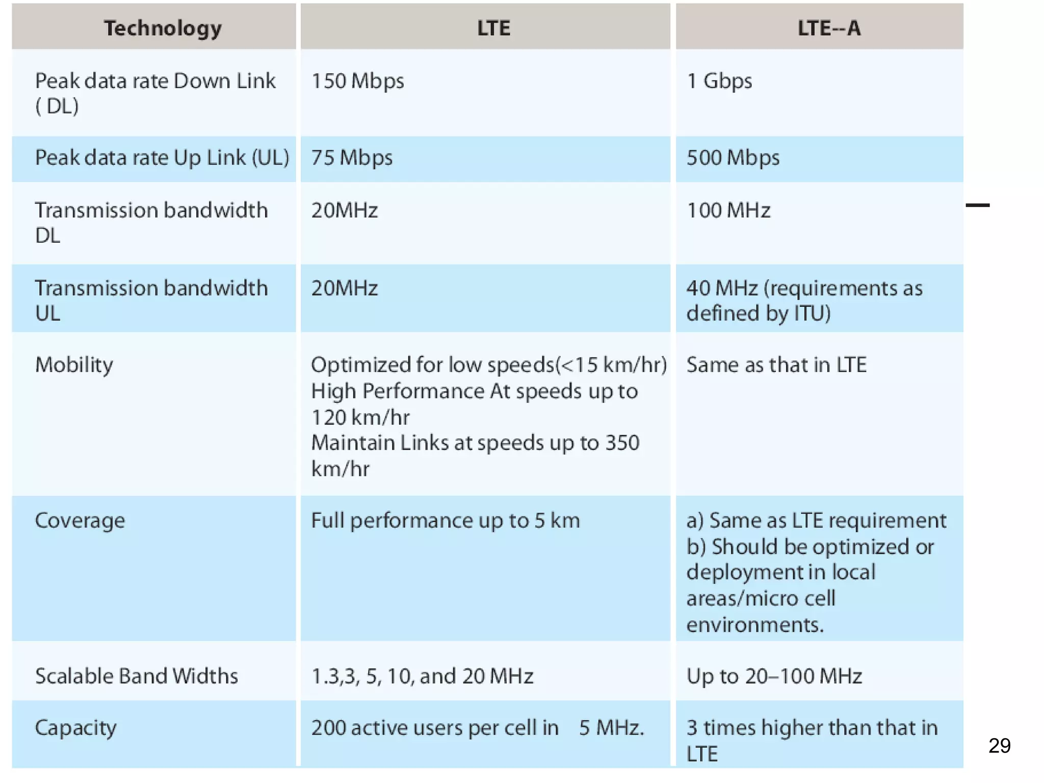
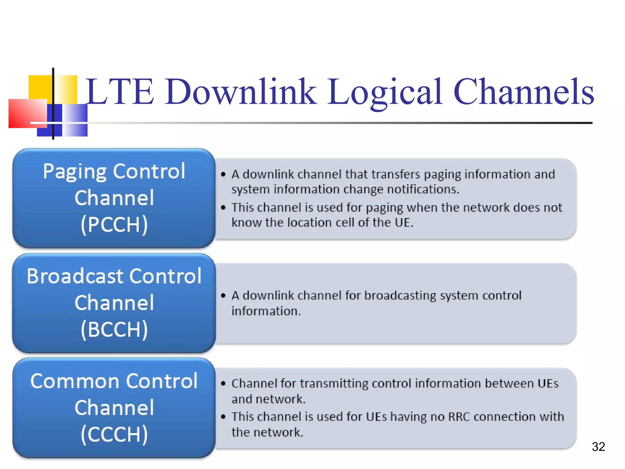
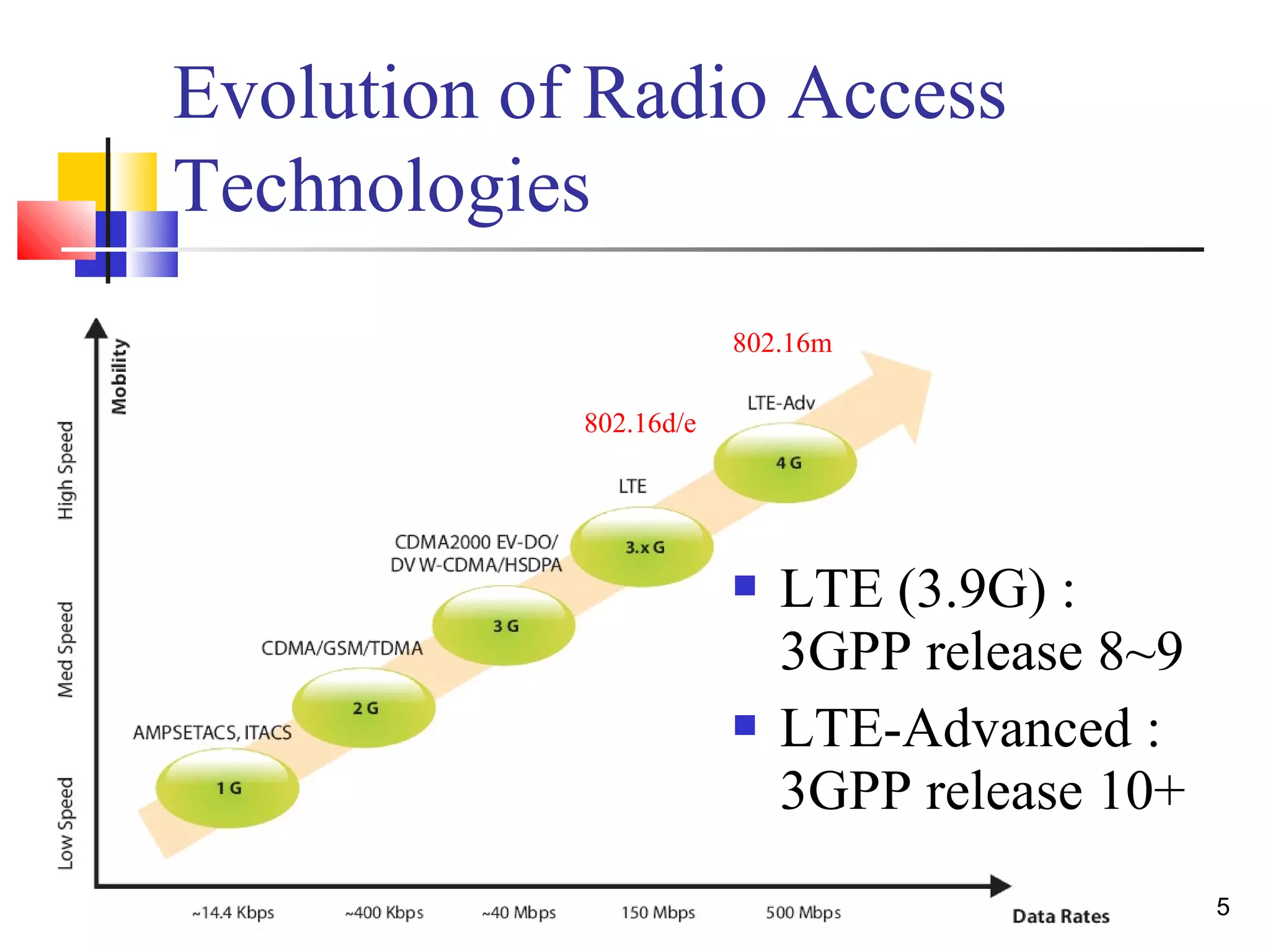
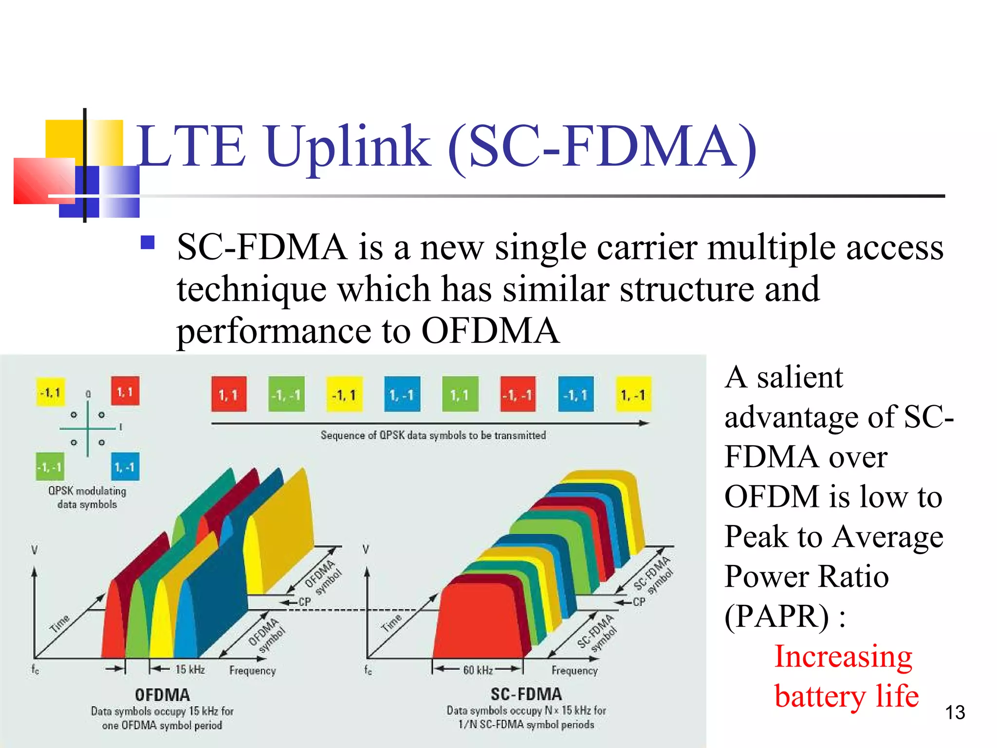
This document provides an introduction to 3GPP Long Term Evolution (LTE) technology. It discusses the history and basic concepts of LTE, including the use of OFDMA for downlink and SC-FDMA for uplink transmission. It also compares LTE to LTE-Advanced, which supports larger bandwidths up to 100MHz and peak data rates of 1Gbps through techniques like carrier aggregation. The document outlines the evolution of radio access technologies and key aspects of the LTE protocol.
![16
Resource Grid
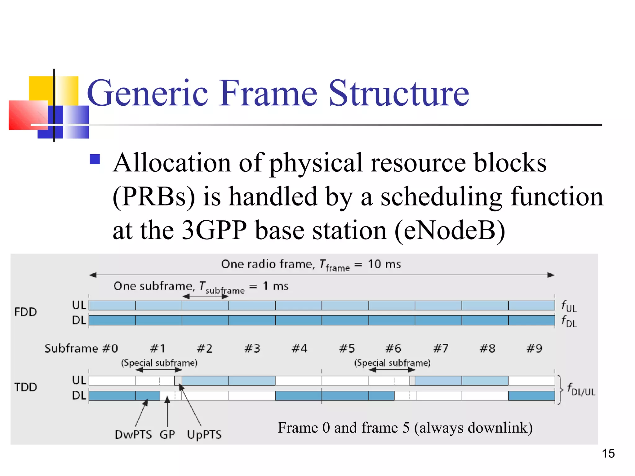
One frame is 10ms
10 subframes
One subframe is 1ms
2 slots
One slot is 0.5ms
N resource blocks
[ 6 < N < 110]
One resource block is 0.5ms
and contains 12 subcarriers
from each OFDM symbol](https://image.slidesharecdn.com/anintroductionof3gpplongtermevolutionlte-141210133924-conversion-gate01/75/An-introduction-of-3-gpp-long-term-evolution-lte-16-2048.jpg)