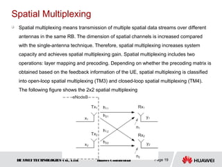
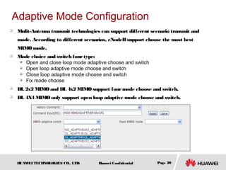
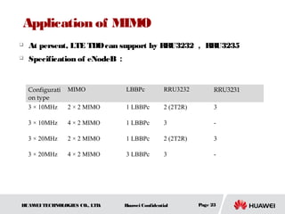
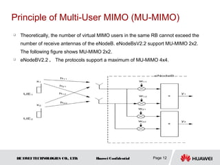
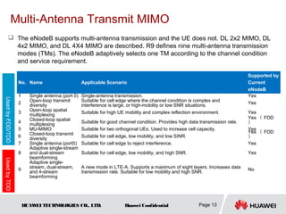
The document is an internal training presentation on LTE system multiple antenna techniques. It provides an overview of MIMO and beamforming concepts and principles, including the advantages of multi-antenna techniques, classifications of MIMO techniques, principles of multi-antenna receive and transmit MIMO, open-loop and closed-loop spatial multiplexing, and adaptive mode configuration. The goal is for trainees to understand the concepts and basic principles of MIMO and beamforming in LTE systems.
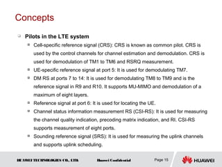
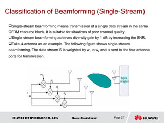
An overview of 5G NR key technical features and enhancements for massive MIMO, mmWave, etc.
Presented by Yinan Qi, Samsung Electronics R&D Institute UK at Cambridge Wireless event Radio technology for 5G – making it work
*** SHARED WITH PERMISSION ***
An overview of 5G NR key technical features and enhancements for massive MIMO, mmWave, etc.
Presented by Yinan Qi, Samsung Electronics R&D Institute UK at Cambridge Wireless event Radio technology for 5G – making it work
*** SHARED WITH PERMISSION ***
Describes key network elements and interfaces of LTE architecture. The steps of LTE/EPC Attach procedure are also illustrated.
Video at: https://www.youtube.com/playlist?list=PLgQvzsPaZX_bimBc5Wu4m6-cVD4bZDav9
LTE Advanced carrier aggregation, it is possible to utilise more than one carrier and in this way increase the overall transmission bandwidth. These channels or carriers may be in contiguous elements of the spectrum, or they may be in different bands.
This documents will cover basic LTE principles along with some brief impression about LTE features. Additionally, LTE Link Budget, LTE Coverage & Capacity Planning and Cell Radius calculation methodology have been depicted comprehensively in this document.
What is 5G NR all about? Check out this presentation to see all the key design components of this new unifying air interface for the next decade and beyond.
LTE Measurement: How to test a device
This course provides an overview with practical examples and exercises on how to test a LTE-capable device while performing standardized RF measurements such as power, signal quality, spectrum and receier sensitivity, and how to automate these measurements in a simple and cost-effective way. We will present testing of LTE handsets in terms of protocol signaling scenarios and handover to other radio technologies for interoperability. This course will demonstrate end-to-end (E2E), throughput and application testing using the Rohde & Schwarz R&S®CMW500 Wideband Radio Communication Tester. Examles of application tests are voice over LTE, (VoLTE) or Video over LTE.
Min input and min output of the system can be conduct by the process of interest in the process of view of synchronisation and software Engineer at the system can be a good idea for this colour combination of view of the best part of the system can be conduct by the process of view till now I'm interested for the system based engineering and technology related issues in college and software engineer h today’s increasing demand for security, especially in public places such as
airports, train stations, supermarkets, schools, and crowded street, surveillance cameras are
used for monitoring daily activities and detecting abnormal events. This task focuses on the
localization of anomalies using both temporal and partial information in videos. Anomalies
can be defined as events deviating from normal behavior [1], e.g., fighting, sneaking,
or unattended bags at an airport. The purpose of using surveillance cameras is the early
detection of anomalous human behaviors. This is a critical task in many cases where human
intervention is necessary, e.g., for crime prevention or countering terrorism. However,
this process requires labor-intensive and continuous human attention, which is a tedious
process, since abnormal events only happen 0.01% of the time and 99.9% of the surveillance
time is wasted [2]. Moreover, a surveillance system produces a lot of redundant video data,
which require unnecessary storage space. For reducing human errors and storage costs, it
is necessary to build an efficient surveillance system for detecting any strange behaviors
that may lead to dangerous situations. This requires deep and comprehensive study of
human activity recognition, to understand the features representative of each action.
Anomaly detection in video has a wide range of applications, such as for traffic
accident detection, criminal activity detection, and illegal activity detection. In addition,
detecting anomalous items or abandoned objects, such as guns or knifes, is necessary in
sensitive area
Performance Analysis of MIMO-LTE for MQAM over Fading ChannelsIOSRJECE
LTE (Long Term Evolution) is a 3GPP (Third Generation Partnership Project) wireless standards which uses the standard OFDMA (Orthogonal Frequency Division Multiple Access) modulation, MU-MIMO (Multiuser Multiple Input Multiple Output) technology and different multipath fading models. LTE uses the spectrum more efficiently to deliver high speed data. This paper characterizes the downlink performance of LTE. The MIMO technology which provides high data rate applications to the users made a breakthrough in wireless communication and is defined in the LTE standard. The performance is characterized in terms of BER (Bit Error Rate). In this paper the LTE system is modelled and simulated using MATLAB and the BER for 2×2 and 4×4 MIMO-LTE using 16QAM and 64QAM modulation schemes for Rayleigh fading environment are obtained against different SNR values.
Massive MIMO (also known as “Large-Scale Antenna Systems”, “Very Large MIMO”, “Hyper MIMO”, “Full-Dimension MIMO” and “ARGOS”) makes a clean break with current practice through the use of a large excess of service-antennas over active terminals and time division duplex operation. Extra antennas help by focusing energy into ever-smaller regions of space to bring huge improvements in throughput and radiated energy efficiency. Other benefits of massive MIMO include the extensive use of inexpensive low-power components, reduced latency, simplification of the media access control (MAC) layer, and robustness to intentional jamming. The anticipated throughput depend on the propagation environment providing asymptotically orthogonal channels to the terminals, but so far experiments have not disclosed any limitations in this regard. While massive MIMO renders many traditional research problems irrelevant, it uncovers entirely new problems that urgently need attention: the challenge of making many low-cost low-precision components that work effectively together, acquisition and synchronization for newly-joined terminals, the exploitation of extra degrees of freedom provided by the excess of service-antennas, reducing internal power consumption to achieve total energy efficiency reductions, and finding new deployment scenarios.
The Study and Analysis of Effect of MultiAntenna Techniques on LTE network wi...Eswar Publications
Long Term Evolution (LTE) system adapts advanced Multiple Input Multiple Output (MIMO) antenna techniques on both uplink and downlink to achieve high peak data rates and higher system throughput. This enables LTE to support multimedia applications beyond web browsing and voice, which demands higher bandwidth configurations. LTE employs Orthogonal Frequency Division Multiple Access (OFDMA) in downlink
to support spectrum flexibility in order to use upto 20MHz system bandwidth to improve the system throughput and robustness. Therefore the combined study of multi-antenna techniques and spectrum flexibility usage on the performance of LTE system becomes vital. Hence in this paper, an attempt has been made to evaluate the performance of different multi-antenna techniques with various system bandwidth configurations from 1.4MHz to 20MHz using QualNet 5.2 network simulator. The multi-antenna techniques considered for performance evaluation are Single Input Single Output (SISO), Multiple Input Single Output (MISO) and Multiple Input
Multiple Output (MIMO). The performance metrics such as aggregate bytes received, average throughput, average delay and average jitter are considered for simulation study.
The aim of this paper is to determine the viability of Indoor Optical Wireless Communication System. This paper introduces Visible Light Communication along with its merits, demerits and applications. Then the main characteristics of VLC system are described, around which the project is designed. Multiple Input-Multiple Output (MIMO) technique is used in the project in order to enhance the data rate of transmission. Instead of using a system of only one LED and one APD, which transmits only one bit at a time, a system of 4 LEDs and 4 APDs is introduced, which increases the data rates by 300% from the previous case. We observe the signal, noise, SNR, BER etc. across the room dimension. Finally, in the last chapter we summarize our results on the basis of MATLAB simulations and propose some modifications to this model that can be implemented in future.
Securing your Kubernetes cluster_ a step-by-step guide to success !KatiaHIMEUR1
Today, after several years of existence, an extremely active community and an ultra-dynamic ecosystem, Kubernetes has established itself as the de facto standard in container orchestration. Thanks to a wide range of managed services, it has never been so easy to set up a ready-to-use Kubernetes cluster.
However, this ease of use means that the subject of security in Kubernetes is often left for later, or even neglected. This exposes companies to significant risks.
In this talk, I'll show you step-by-step how to secure your Kubernetes cluster for greater peace of mind and reliability.
Epistemic Interaction - tuning interfaces to provide information for AI supportAlan Dix
Paper presented at SYNERGY workshop at AVI 2024, Genoa, Italy. 3rd June 2024
https://alandix.com/academic/papers/synergy2024-epistemic/
As machine learning integrates deeper into human-computer interactions, the concept of epistemic interaction emerges, aiming to refine these interactions to enhance system adaptability. This approach encourages minor, intentional adjustments in user behaviour to enrich the data available for system learning. This paper introduces epistemic interaction within the context of human-system communication, illustrating how deliberate interaction design can improve system understanding and adaptation. Through concrete examples, we demonstrate the potential of epistemic interaction to significantly advance human-computer interaction by leveraging intuitive human communication strategies to inform system design and functionality, offering a novel pathway for enriching user-system engagements.
The Art of the Pitch: WordPress Relationships and SalesLaura Byrne
Clients don’t know what they don’t know. What web solutions are right for them? How does WordPress come into the picture? How do you make sure you understand scope and timeline? What do you do if sometime changes?
All these questions and more will be explored as we talk about matching clients’ needs with what your agency offers without pulling teeth or pulling your hair out. Practical tips, and strategies for successful relationship building that leads to closing the deal.
Transcript: Selling digital books in 2024: Insights from industry leaders - T...BookNet Canada
The publishing industry has been selling digital audiobooks and ebooks for over a decade and has found its groove. What’s changed? What has stayed the same? Where do we go from here? Join a group of leading sales peers from across the industry for a conversation about the lessons learned since the popularization of digital books, best practices, digital book supply chain management, and more.
Link to video recording: https://bnctechforum.ca/sessions/selling-digital-books-in-2024-insights-from-industry-leaders/
Presented by BookNet Canada on May 28, 2024, with support from the Department of Canadian Heritage.
JMeter webinar - integration with InfluxDB and GrafanaRTTS
Watch this recorded webinar about real-time monitoring of application performance. See how to integrate Apache JMeter, the open-source leader in performance testing, with InfluxDB, the open-source time-series database, and Grafana, the open-source analytics and visualization application.
In this webinar, we will review the benefits of leveraging InfluxDB and Grafana when executing load tests and demonstrate how these tools are used to visualize performance metrics.
Length: 30 minutes
Session Overview
-------------------------------------------
During this webinar, we will cover the following topics while demonstrating the integrations of JMeter, InfluxDB and Grafana:
- What out-of-the-box solutions are available for real-time monitoring JMeter tests?
- What are the benefits of integrating InfluxDB and Grafana into the load testing stack?
- Which features are provided by Grafana?
- Demonstration of InfluxDB and Grafana using a practice web application
To view the webinar recording, go to:
https://www.rttsweb.com/jmeter-integration-webinar
State of ICS and IoT Cyber Threat Landscape Report 2024 previewPrayukth K V
The IoT and OT threat landscape report has been prepared by the Threat Research Team at Sectrio using data from Sectrio, cyber threat intelligence farming facilities spread across over 85 cities around the world. In addition, Sectrio also runs AI-based advanced threat and payload engagement facilities that serve as sinks to attract and engage sophisticated threat actors, and newer malware including new variants and latent threats that are at an earlier stage of development.
The latest edition of the OT/ICS and IoT security Threat Landscape Report 2024 also covers:
State of global ICS asset and network exposure
Sectoral targets and attacks as well as the cost of ransom
Global APT activity, AI usage, actor and tactic profiles, and implications
Rise in volumes of AI-powered cyberattacks
Major cyber events in 2024
Malware and malicious payload trends
Cyberattack types and targets
Vulnerability exploit attempts on CVEs
Attacks on counties – USA
Expansion of bot farms – how, where, and why
In-depth analysis of the cyber threat landscape across North America, South America, Europe, APAC, and the Middle East
Why are attacks on smart factories rising?
Cyber risk predictions
Axis of attacks – Europe
Systemic attacks in the Middle East
Download the full report from here:
https://sectrio.com/resources/ot-threat-landscape-reports/sectrio-releases-ot-ics-and-iot-security-threat-landscape-report-2024/
DevOps and Testing slides at DASA ConnectKari Kakkonen
My and Rik Marselis slides at 30.5.2024 DASA Connect conference. We discuss about what is testing, then what is agile testing and finally what is Testing in DevOps. Finally we had lovely workshop with the participants trying to find out different ways to think about quality and testing in different parts of the DevOps infinity loop.
Connector Corner: Automate dynamic content and events by pushing a buttonDianaGray10
Here is something new! In our next Connector Corner webinar, we will demonstrate how you can use a single workflow to:
Create a campaign using Mailchimp with merge tags/fields
Send an interactive Slack channel message (using buttons)
Have the message received by managers and peers along with a test email for review
But there’s more:
In a second workflow supporting the same use case, you’ll see:
Your campaign sent to target colleagues for approval
If the “Approve” button is clicked, a Jira/Zendesk ticket is created for the marketing design team
But—if the “Reject” button is pushed, colleagues will be alerted via Slack message
Join us to learn more about this new, human-in-the-loop capability, brought to you by Integration Service connectors.
And...
Speakers:
Akshay Agnihotri, Product Manager
Charlie Greenberg, Host
Neuro-symbolic is not enough, we need neuro-*semantic*Frank van Harmelen
Neuro-symbolic (NeSy) AI is on the rise. However, simply machine learning on just any symbolic structure is not sufficient to really harvest the gains of NeSy. These will only be gained when the symbolic structures have an actual semantics. I give an operational definition of semantics as “predictable inference”.
All of this illustrated with link prediction over knowledge graphs, but the argument is general.
Training document e ran2.2_lte tdd system multiple antenna techniques(mimo and beamforming)-20111010-a-1.0
1. 08/23/12 Internal
LTE System Multiple
Antenna Techniques
www.huawei.com
eRAN2.2 (MIMO and Beamforming)
HUAW TECHNOLOGIES CO., LTD.
EI Huawei Confidential
2. Training Objectives
After completing this course, you will be able to:
Understand the concepts relevant to the MIMO and Beamforming.
Understand basic principle of MIMO and Beamforming.
References:
3GPP TS 36.211: Physical Channels and Modulation
3GPP TS 36.213: Physical layer procedures
3GPP TS 36.306: User Equipment (UE) radio access capabilities
FPD: MIMO and Beamforming Feature Documentation
HUAW TECHNOLOGIES CO., LTD.
EI Huawei Confidential Page2
3. Contents
Background and Overview of the LTE MIMO Techniques
Principles and Application of the MIMO Techniques
Principles and Application of Beamforming
HUAW TECHNOLOGIES CO., LTD.
EI Huawei Confidential Page3
4. Background of Multi-Antenna Techniques
Fifty years ago, Shannon gave the maximum efficiency that a time and
frequency communication system can achieve.
S
C = B × log 2 1 + ( bit / s )
N
The rapid development of wireless communications poses increasingly higher
requirement for system capacity and spectral efficiency. Various algorithms
are invented, such as spreading the system bandwidth, optimizing the
modulation scheme, or using complex code division multiple access. These
methods are limited: Bandwidth cannot be expanded indefinitely; modulation
orders cannot increase indefinitely; channels between a CDMA system are
not ideally orthogonal. Another dimension, that is, MIMO, is invented to better
use the spatial resource. As expressed in the following equation, if multiple
antennas are used, the capacity is increased by a multiplication of the
number of antennas used.
S
C = B × log 2 1 + ( bit / s ) × M
N
HUAW TECHNOLOGIES CO., LTD.
EI Huawei Confidential
5. Advantages of Multi-Antenna Techniques
The LTE system improves system performance for cell edge users and brings
stable and reliable service experience for users. Therefore, multi-antenna
techniques can make use of the spatial resource and increase the wireless
transmission capacity many folds without increasing the transmit power and
bandwidth.
Array gain Improved Increased
system coverage spectral
efficiency
Diversity gain Improved
system capacity
Spatial multiplexing
gain
Increased peak
rate
Co-channel interference
reduction
HUAW TECHNOLOGIES CO., LTD.
EI Huawei Confidential Page 5
6. Contents
Background and Overview of the LTE MIMO Techniques
Principles and Application of the MIMO Techniques
Principles and Application of Beamforming
HUAW TECHNOLOGIES CO., LTD.
EI Huawei Confidential Page6
7. Principles of the MIMO Techniques
MIMO is an important technique in the LTE system. MIMO means use of
multiple antennas at both the transmitter and receiver. MIMO can better
utilize the spatial resource and increase spectral efficiency, achieving array
gain, diversity gain, multiplexing gain, and interference rejection gain,
providing higher system capacity, wider coverage, and higher user rate.
HUAW TECHNOLOGIES CO., LTD.
EI Huawei Confidential Page 7
8. Classification of MIMO Techniques
Depending on whether the spatial channel information is used, MIMO techniques are
classified into open-loop MIMO and closed-loop MIMO.
• Open-loop MIMO: The UE does not feed back information, the eNodeB is not informed of the
UE situation. The protocols support single-stream (TM2) or multi-stream (TM3).
• Closed-loop MIMO: The UE feeds back information. The gain has a positive correlation with the
accuracy of the feedback information. The protocols support single-stream (TM4) or multi-
stream (TM6). At present, the feedback granularity supported by the reference signal in port 2
is large and closed-loop MIMO can hardly achieve gains. Closed-loop MIMO requires low UE
mobility. At present, the eNodeB cannot accurately estimate the UE movement speed with an
error of more than 30 km/h.
Depending on the number of simultaneously transmitted spatial data streams, MIMO
techniques are classified into spatial diversity and spatial multiplexing.
These modes are described in detail in the following pages.
MIMO Technique MIMO Mode Feature List in FDD Feature List in TDD
UL 2-Antenna Receive Diversity UL 2-Antenna Receive Diversity
UL 4-Antenna Receive Diversity UL 4-Antenna Receive Diversity
Receive diversity
Multi-antenna UL Interference Rejection UL Interference Rejection Combining
receive Combining UL 8-Antenna Receive Diversity
UL 2x2 MU-MIMO UL 2x2 MU-MIMO
MU-MIMO
UL 2x4 MU-MIMO UL 2x4 MU-MIMO
Open-loop transmit diversity
2x2 MIMO
Closed-loop transmit diversity 2x2 MIMO
Multi-antenna
Open-loop spatial multiplexing 4x2 MIMO
transmit 4x2 MIMO
Closed-loop spatial DL 4x4 MIMO
multiplexing
HUAW TECHNOLOGIES CO., LTD.
EI Huawei Confidential
Page 8
9. Principle of Multi-Antenna Receive MIMO
eRAN2.2 supports UL 2-Antenna Receive Diversity and optional UL 4-Antenna Receive
Diversity and UL 8-Antenna Receive Diversity.
The following figure shows the block diagram of receive diversity. The UE uses one
antenna to transmit signals; different UEs use different time and frequency resources.
The eNodeB uses multiple antennas to receive signals and combine the received
signals to maximize SINR, therefore obtaining diversity gain and array gain, increasing
the cell coverage and improving single-user capacity.
HUAW TECHNOLOGIES CO., LTD.
EI Huawei Confidential Page 9
10. Principle of Multi-Antenna Receive MIMO
Mechanism of Signal Combination:
An MMSE receiver uses receive beamforming targeted at a UE. The receiver adjusts the
combined weight and changes the direction of the major lobe and side lobe to maximize
the SINR of the received signals.
There are two combination algorithms for UL receive diversity.
Maximum ratio combining (MRC) and interference rejection combining (IRC) can both
obtain diversity gain and array gain, improving system performance. MRC and IRC are
suitable for environments with different interference characteristics. MRC receivers and
IRC receivers are implementation of MMSE receivers in different scenarios.
HUAW TECHNOLOGIES CO., LTD.
EI Huawei Confidential Page 10
11. Specification of Multi-Antenna Receive MIMO
Adaptive Switchover Between MRC and IRC
For eNodeBs V2.2, IRC is optional. If IRC is not selected, an eNodeB
uses MRC. If IRC is selected, an eNodeB adaptively selects IRC or MRC
depending on the current radio channel quality.
If there is separable strong colored interference, the system automatically
uses IRC algorithm.
If there is no separable strong colored interference, the system
automatically rolls back to MRC algorithm.
In UL 2x2 MU-MIMO mode, the eNodeB does not support UL Interference
Rejection Combining or UL 2-Antenna Receive Diversity
In UL 4-Antenna Receive Diversity mode, the eNodeB supports UL
Interference Rejection Combining.
HUAW TECHNOLOGIES CO., LTD.
EI Huawei Confidential Page 11
12. Principle of Multi-User MIMO (MU-MIMO)
Theoretically, the number of virtual MIMO users in the same RB cannot exceed the
number of receive antennas of the eNodeB. eNodeBsV2.2 support MU-MIMO 2x2.
The following figure shows MU-MIMO 2x2.
eNodeBV2.2 , The protocols support a maximum of MU-MIMO 4x4.
HUAW TECHNOLOGIES CO., LTD.
EI Huawei Confidential Page 12
13. Multi-Antenna Transmit MIMO
The eNodeB supports multi-antenna transmission and the UE does not. DL 2x2 MIMO, DL
4x2 MIMO, and DL 4X4 MIMO are described. R9 defines nine multi-antenna transmission
modes (TMs). The eNodeB adaptively selects one TM according to the channel condition
and service requirement.
Supported by
No. Name Applicable Scenario Current
eNodeB
1 Single antenna (port 0) Single-antenna transmission. Yes
Used by FDD/TDD
Open-loop transmit Suitable for cell edge where the channel condition is complex and
2 Yes
diversity interference is large, or high-mobility or low SNR situations.
Open-loop spatial
3 Suitable for high UE mobility and complex reflection environment. Yes
multiplexing
Closed-loop spatial Yes ( FDD
4 multiplexing Suitable for good channel condition. Provides high data transmission rate. )
5 MU-MIMO Suitable for two orthogonal UEs. Used to increase cell capacity. Yes
Closed-loop transmit Yes ( FDD
6 diversity Suitable for cell edge, low mobility, and low SINR. )
7 Single antenna (port5) Suitable for cell edge to reject interference. Yes
Adaptive single-stream
8 and dual-stream Suitable for cell edge, low mobility, and high SNR. Yes
beamforming
Used by TDD
Adaptive single-
stream, dual-stream, A new mode in LTE-A. Supports a maximum of eight layers. Increases data
9 No
and 4-stream transmission rate. Suitable for low mobility and high SNR.
beamforming
HUAW TECHNOLOGIES CO., LTD.
EI Huawei Confidential Page 13
14. Concepts
Port
A port is a logical port and does not necessarily correspond to an antenna. There can be
multiple ports. The LTE protocols support a maximum of eight physical antennas. Ports
correspond to pilot formats, whereas the number of physical antennas has not direct
relationship with the pilot formats.
Port 0 to port 3: Ports for transmitting common pilots. Usually the number of ports for physical
broadcast channels and downlink control channels is the same as that for common pilots.
Port 5: A port defined in the LTE for supporting single-stream beamforming. The data of a
single port can be weighted and mapped to multiple physical antennas.
Port 6: A port for locating the pilot.
Port 7 to port 14: Similar to port 5. Supports a maximum of 8 layers. The data of 8 ports can
be weighted and mapped to 8 physical antennas. Used for dual-stream beamforming.
Port 15 to port 22: CSI-RS port.
Maximum number of streams = Number of logical antenna ports [2 ports, 4 ports, or 8 ports]
HUAW TECHNOLOGIES CO., LTD.
EI Huawei Confidential Page 14
15. Concepts
Pilots in the LTE system
Cell-specific reference signal (CRS): CRS is known as common pilot. CRS is
used by the control channels for channel estimation and demodulation. CRS is
used for demodulation of TM1 to TM6 and RSRQ measurement.
UE-specific reference signal at port 5: It is used for demodulating TM7.
DM RS at ports 7 to 14: It is used for demodulating TM8 to TM9 and is the
reference signal in R9 and R10. It supports MU-MIMO and demodulation of a
maximum of eight layers.
Reference signal at port 6: It is used for locating the UE.
Channel status information measurement RS (CSI-RS): It is used for measuring
the channel quality indication, precoding matrix indication, and RI. CSI-RS
supports measurement of eight ports.
Sounding reference signal (SRS): It is used for measuring the uplink channels
and supports uplink scheduling.
HUAW TECHNOLOGIES CO., LTD.
EI Huawei Confidential Page 15
16. Ce ll-s pe cific Re fe re nce S igna l (CRS )
Normal CP , downlink reference signal map relationship.
HUAW TECHNOLOGIES CO., LTD.
EI Huawei Confidential Page 16
17. Open-Loop Transmit Diversity
In open-loop transmit diversity (TM2), space-frequency block coding (SFBC) is
used if the number of transmit antennas is 2; SFBC and frequency switched
transmit diversity (FSTD) are used if the number of transmit antennas is 4.
SFBC: For two-way transmit (DL 2x2 MIMO), the transmit diversity uses SFBC,
where X1 and x2 are the information to be transmitted before SFBC, * indicates
conjugate operation, f1 and f2 are different subcarriers, and Tx1 and Tx2 are different
transmit antennas. SFBC codes x1 and x2 to different antennas and subcarriers for
transmission: x1 over Tx1 f1, x2 over Tx1 f2, -x2* over Tx2 f1, and x1* over Tx2 f2. Therefore,
by transmitting copies of x1 and x2 over different antennas and frequencies, SFBC
achieves diversity gain.
HUAW TECHNOLOGIES CO., LTD.
EI Huawei Confidential Page 17
18. Open-Loop Transmit Diversity
SFBC+FSTD
For 4-way transmit (DL 4x2 MIMO or DL 4X4 MIMO), SFBC and FSTD are used together.
In FSTD, some of the transmit antennas are selected sequentially in frequency for
transmission.
The transport format of SFBC+FSTD is as follows: x1, x2, x3, and x4 are information to be
transmitted before coding; f1 to f4 are different subcarriers; Tx1 and Tx4 are different
transmit antennas; * indicates conjugate operation; 0 indicates no information
transmitted. In SFBC+FSTD, x1 to x4 are coded to different antennas and subcarriers for
transmission; the transmit antennas are selected. Like SFBC, SFBC+FSTD achieves
diversity gain by transmitting copies over different antennas and frequencies.
HUAW TECHNOLOGIES CO., LTD.
EI Huawei Confidential Page 18
19. Spatial Multiplexing
Spatial multiplexing means transmission of multiple spatial data streams over different
antennas in the same RB. The dimension of spatial channels is increased compared
with the single-antenna technique. Therefore, spatial multiplexing increases system
capacity and achieves spatial multiplexing gain. Spatial multiplexing includes two
operations: layer mapping and precoding. Depending on whether the precoding matrix is
obtained based on the feedback information of the UE, spatial multiplexing is classified
into open-loop spatial multiplexing (TM3) and closed-loop spatial multiplexing (TM4).
The following figure shows the 2x2 spatial multiplexing
HUAW TECHNOLOGIES CO., LTD.
EI Huawei Confidential Page 19
20. Adaptive Mode Configuration
Mulit-Antenna transmit technologies can support different scenario transmit and
mode. According to different scenarios, eNodeB support choose the most best
MIMO mode.
Mode choice and switch four type:
Open and close loop mode adaptive choose and switch
Open loop adaptive mode choose and switch
Close loop adaptive mode choose and switch
Fix mode choose
DL 2x2 MIMO and DL 4x2 MIMO support four mode choose and switch.
DL 4X4 MIMO only support open loop adaptive mode choose and switch.
HUAW TECHNOLOGIES CO., LTD.
EI Huawei Confidential Page 20
21. Configura tions of MIMO
HUAW TECHNOLOGIES CO., LTD.
EI Huawei Confidential Page 21
22. Configura tion of MU-MIMO
HUAW TECHNOLOGIES CO., LTD.
EI Huawei Confidential Page 22
23. Application of MIMO
At persent, LTE TDD can support by RRU3232 , RRU3235
Specification of eNodeB:
Configurati MIMO LBBPc RRU3232 RRU3231
on type
3 × 10MHz 2 × 2 MIMO 1 LBBPc 2 (2T2R) 3
3 × 10MHz 4 × 2 MIMO 1 LBBPc 3 -
3 × 20MHz 2 × 2 MIMO 1 LBBPc 2 (2T2R) 3
3 × 20MHz 4 × 2 MIMO 3 LBBPc 3 -
HUAW TECHNOLOGIES CO., LTD.
EI Huawei Confidential Page 23
24. Contents
Background and Overview of the LTE MIMO Techniques
Principles and Application of the MIMO Techniques
Principles and Application of Beamforming
HUAW TECHNOLOGIES CO., LTD.
EI Huawei Confidential Page24
25. Principles of Beamforming
Beamforming is a downlink multi-antenna technique. The transmitter of an
eNodeB weights the data before transmission, forming narrow beams and
aiming the energy at the target user, as shown in the following figure.
Beamforming does not require the UE to feed back information or use multiple
antennas to transmit data. The direction of incoming wave and the path loss
information are obtained by measuring the uplink received signal.
The benefits of beamforming are as follows:
Increased SINR in the direction of incoming wave from the UE.
Increased system capacity and coverage.
HUAW TECHNOLOGIES CO., LTD.
EI Huawei Confidential
26. Classification of Beamforming Techniques
DOA Beamforming and MIMO Beamforming:
Direction of Arrival (DOA) beamforming: The eNodeB estimates the direction of arrival of the
signal, uses the DOA information to calculate the transmit weight, and targets the major lobe of the
transmit beam at the best direction.
MIMO beamforming: The eNodeB uses the channel information to calculate the transmit weight,
forming a beam.
In the industry, the TDD system uses open-loop Beamforming and the FDD
system uses closed-loop Beamforming. Huawei eNodeB supports open-
loop Beamforming.
HUAW TECHNOLOGIES CO., LTD.
EI Huawei Confidential Page 26
27. Classification of Beamforming (Single-Stream)
Single-stream beamforming means transmission of a single data stream in the same
OFDM resource block. It is suitable for situations of poor channel quality.
Single-stream beamforming achieves diversity gain by 1 dB by increasing the SNR.
Take 4-antenna as an example. The following figure shows single-stream
beamforming. The data stream S is weighted by w1 to w4 and is sent to the four antenna
ports for transmission.
HUAW TECHNOLOGIES CO., LTD.
EI Huawei Confidential Page 27
28. Classification of Beamforming (Dual-Stream)
Dual-stream beamforming means transmission of two data streams in the same OFDM
resource block, leading to spatial multiplexing. It is suitable for situations of good channel
quality.
Take 4-antenna as an example. The following figure shows dual-stream beamforming.
There are two data streams S1 and S2; each antenna has two weights wi1 and wi2. S1 is
weighted by four weights: w11 to w41; S2 is weighted by another four weights w12 to w42. The
weighted streams are summed and sent to the four antenna ports for transmission.
HUAW TECHNOLOGIES CO., LTD.
EI Huawei Confidential Page 28
29. Engineering Guidelines of Beamforming
Before configuring beamforming antennas, you need to understand the correspondence
between the port No. and the co-polarization of cross-polarized antennas. The following
figure shows the connection between RRU ports and antenna element of the four or
eight antennas.
At present, the RRU models in LTE TDD that support beamforming are RRU3232,
RRU3233, and RRU3235.
4-antenna cross 4-antenna linear 4-antenna circular 8-antenna cross
polarization mapping polarization mapping polarization mapping polarization mapping
HUAW TECHNOLOGIES CO., LTD.
EI Huawei Confidential Page 29
30. Beamforming Cell Configuration
Add an LBBP by running the ADD BRD command with Mode set to TDD_ENHANCE.
After adding the cell, run the following commands to turn on the beamforming
measurement switch and algorithm switch:
MOD MEASURESWITCH: UlintfMeasSwitch=SW_BfNValidMeas-
1&SW_BfNRankMeas-1&SW_BfSrsMeas-1;
MOD CELLALGOSWITCH: LocalCellId=0, BfAlgoSwitch=BfSwitch-1;
HUAW TECHNOLOGIES CO., LTD.
EI Huawei Confidential Page 30
31. S pe cifica tion of Be a mforming
Configuration Type MIMO LBBPc RRU3232
3 × 10MHz 4T4R Beamforming 1 LBBPc 3
3 × 20MHz 4T4R Beamforming 3 LBBPc 3
Configuration Type MIMO LBBP RRU3232
6 × 20MHz 4T4R Beamforming 6 LBBPc 6
Configuration Type MIMO LBBP RRU3233
3 × 20MHz 8T8R 3 LBBPc 3(each RRU need two
Beamforming fibers )
HUAW TECHNOLOGIES CO., LTD.
EI Huawei Confidential Page 31
32. KPI of Beamforming
Leading 4x2 Beamforming Enhanced the Capacity
Always Leading in Beamforming Test Result in Japan SBM Network
3GPP R8 3GPP R9 3GPP R10
single- dual- Multi-User
stream stream Beamformin
beamformi beamformi g
ng ng
1st to support
1st to launch
Dual-stream Beamforming
Single-stream
Beamforming
+10%
+15%
+15% Hisilcon Balong710 Chipset
is the first to support
dual-stream beamforming
Hisilcon Balong700 Chipset
is the first to
support single-stream
beamforming >2Mbps >4Mbps >6Mbps
TM7 91.50% 73.40% 60.10%
2011H1 2011H2 2012H1 TM2 82.80% 61.90% 56.10%
HUAW TECHNOLOGIES CO., LTD.
EI Huawei Confidential Page 32
33. KPI of Beamforming
Relevant features
Single-stream beamforming must be enabled before dual-stream beamforming.
Influence on the KPI
Single-stream or dual-stream beamforming has the following influence on the KPI:
Cell average throughput
If the single-stream and dual-stream beamforming is enabled, the signal energy received by
the UE is increased, the MCS is increased at the same UE position, beamforming achieves
higher cell average throughput than transmit diversity. In comparison with no beamforming,
single-stream beamforming increases the cell average throughput by 15% to 25%. In
comparison with single-stream beamforming, adaptive single-stream and dual-stream
beamforming increases the cell average throughput by more than 10%.
Beamforming compared with 2R diversity (UL)
• ~ 30% gain in cell average throughput
• ~ 50% gain in cell edge user throughput
Beamforming compared with 2x2 MIMO (DL)
• ~ 15% gain in cell average throughput
23%~90% increasing in edge user throughput
• ~ 40% gain in cell edge user throughput
HUAW TECHNOLOGIES CO., LTD.
EI Huawei Confidential Page 33
34. Adaptive MIMO and Beamforming
With adaptive beamforming and MIMO, the UE always uses TM of high spectral efficiency under the
same channel condition. In comparison with non-adaptive MIMO or beamforming, adaptive MIMO and
beamforming significantly increases average cell throughput.
If beamforming is used, due to the overhead of UE-specific reference signal, the number of resource
blocks is reduced. Therefore, in case of good channel quality, beamforming throughput is slightly lower
than MIMO throughput. At high UE mobility (higher than 120 km/h), the eNodeB cannot track the
channel change accurately according to the sounding reference signal. In this situation, beamforming
is not suitable.
Adaptive beamforming and MIMO (low Adaptive beamforming and MIMO (high
mobility) mobility)
HUAW TECHNOLOGIES CO., LTD.
EI Huawei Confidential Page 34
35. Adaptive MIMO and Beamforming
The BFMIMOADAPTIVESWITCH parameter is used to select adaptive beamforming or MIMO. The eNodeB selects
beamforming or MIMO according to the value of the parameter, the UE movement speed, and SINR.
If the value of the parameter is NO_ADAPTIVE, the eNodeB does not support adaptive Beamforming and MIMO.
If the value of the parameter is TxD_BF_ADAPTIVE, the eNodeB supports adaptive TM2 (transmit diversity) and
beamforming. There are two scenarios: low UE mobility and high UE mobility. Low UE mobility: For UEs that do not
support R9, single-stream beamforming (TM7) is used; for UEs that support R9, single-stream beamforming (TM7 or
TM8) is used at low SINR and dual-stream beamforming (TM8) is used at high SINR. High UE mobility: Transmit
diversity is used.
If the value of the parameter is MIMO_BF_ADAPTIVE, the eNodeB supports adaptive transmit diversity, dual-stream
MIMO (TM3), and beamforming. There are two scenarios: low UE mobility and high UE mobility. Low UE mobility: For
UEs that do not support R9, single-stream beamforming (TM7) is used at low SINR and dual-stream MIMO (TM3) is
used at high SINR; for UEs that support R9, single-stream beamforming is used at low SINR and dual-stream
beamforming (TM8) is used at high SINR. High UE mobility: Transmit diversity is used at low SINR and dual-stream
MIMO (TM3) is used at high SINR.
HUAW TECHNOLOGIES CO., LTD.
EI Huawei Confidential Page 35
36. Comparison Between Beamforming and Other
Techniques
Though a space diversity system or intelligent antenna system
has multiple transmit or receive antennas, they can transmit only
single-stream data. A MIMO system can transmit single stream or
multiple streams depending on the channel quality.
MIMO requires that the number of receive antennas is not less
than the number of transmit antennas. Space diversity and
intelligent antennas do not have this requirement.
HUAW TECHNOLOGIES CO., LTD.
EI Huawei Confidential Page 36
Array gain: A power gain achieved by combining signals from different antennas based on the correlation between signals and the non-correlation between noises. Signal combining increases the signal to interference plus noise ratio (SINR) of the combined signal. Diversity gain: The performance gain obtained by reducing the fading amplitude (the covariance of SNR). The fading amplitude is reduced by combining signals from different antennas on which the deep fading of the signals are unrelated. Spatial multiplexing gain: A throughput gain achieved by adding spatial channels without increasing the total bandwidth and total TX power. Interference rejection gain: A gain achieved by interference rejection combining or other multi-antenna interference rejection algorithms.
课程名称 华为技术有限公司 版权所有 未经许可不得扩散 P-
MIMO uses the idea of spatial coding. Transmitter: N streams are sent to a channel simultaneously. Each TX signal input can use the same frequency, the same codeword, and be transmitted simultaneously. As long as the channel response of each transmit and receive antennas is independent of each other, MIMO can create multiple parallel spatial channels and use the characteristics of each spatial channel to identify the streams. Receiver: Each antenna receives the code streams of each transmit antenna, uses the characteristics of the parallel spatial channels to combine and decode the received signals, and combine the streams. Multiple streams are transmitted by independent parallel spatial channels to improve the overall data transmission rate.
DL a x b MIMO means that the eNodeB uses a antennas to transmit data and the UE uses b antennas to receive data. UL a x b MU-MIMO means that a UEs use the same resource block to transmit data and the eNodeB uses b antennas to receive data. The MimoAdaptiveSwitch and FixedMimoMode parameters are used to set the MIMO mode to one of the following four modes: Open-loop and closed-loop adaptive, open-loop adaptive, closed-loop adaptive, and fixed mode.
Principles of receive diversity: Signal x transmitted by the UE arrives at antennas r 1 to r m of the eNodeB over different channels. The eNodeB multiplies the received signals with weights w i * and combines the signals to obtain signal y. The combined signal y can be expressed as follows: y=W H (Hx+N) where W=(w 1 * …… w m * ) H is the weight vector of the antennas. H=(h 1 …… h m ) H is the spatial channel matrix and h i is the channel coefficient. The amplitude and phase of a signal are changed after passing a channel. The signal is multiplied by the channel coefficient to obtain the signals that passes the channel. N=(n 1 …… n m ) H is the noise vector of the antennas. x is the transmit signal. Due to the fading characteristics of a radio channel, the radio channel between a transmitter and a receiver experiences deep fading (10 dB to 20 dB) periodically, causing SINR fluctuation. However, deep fading in different antennas does not occur simultaneously, or the probability of simultaneous occurrence is low. When signals received by different antennas are combined, the probability of deep fading is greatly reduced, achieving diversity gain. The white noise in different antennas is not correlated. The combined noise power is unchanged, but the signal energy is increased by many folds, achieving array gain. Array gain is usually proportional to the number of receive antennas. That is, the array gain of a 2-antenna receive system is 3dB and that of a 4-antenna receive system is 6dB. The key of receive diversity is in signal combination algorithms. There are two types of signal combination algorithms: m aximum ratio combining and i nterference rejection combining . Relevant concepts Minimum m ean s quare e rror (MMSE): MMSE between the estimated transmit signal and actual transmit signal. White noise: Noise whose power spectrum density is evenly distributed in the frequency or space domain. Colored interference: Interference whose power spectrum density is unevenly distributed in the frequency or space domain. MMSE receiver: An MMSE receiver uses receive beamforming targeted at a UE. The receiver adjusts the combined weight and changes the direction of the major lobe and side lobe to maximize the SINR of the combined signals.
where x 0 is the signal, n i (i=1,2,…m) is the interference, h i (p) (p=0, 1) is the channel coefficient, n’ and n’’ are white noise (additive white Gaussian noise), w (p) is the receive weight, r P+1 is the received signal, y is the combined signal, p is the antenna sequential No. x 0 and n pass their respective radio channels h i (p) and are summed in the antennas. Also summed is the additive white Gaussian noise n’ and n’’ brought by the intermediate frequency system. The received signal is r P+1 . The MMSE receiver adjusts the w (p) of each antenna to combine the received signals in maximum ratio and in minimum mean square error. Due to the constraint in the number of antennas, the MMSE receiver cannot simultaneously minimize the gain of the interference achieved by the side lobe while target the major lobe at the signal source. Rather, the receiver finds a tradeoff between minimizing interference gain and maximizing signal gain to maximize the SINR of the combined signal. Assuming that the interference and noise are both white in the space, MRC receivers use MRC algorithm to achieve MMSE. Assuming that there is colored interference, IRC receivers use IRC algorithm to achieve MMSE. The interference rejection performance of IRC algorithm depends on the interference characteristics. Only separable spatial colored interference can be rejected by IRC algorithm. The performance of IRC algorithm depends on the accuracy of estimating the interference characteristics by the algorithm. In the following scenarios, IRC algorithm provides no advantage. If the interference to the antenna channels is strongly correlated to the signals to the antenna channels, the interference and signals are inseparable. In this case, IRC performance is worse than MRC performance. If the interference is white or weak, theoretically IRC algorithm is equivalent to MRC algorithm; their performance is the same. In practice, there is an error in estimating the interference characteristics. Without interference, IRC performance is slightly worse than MRC performance. The eNodeB measures the spatial color of the interference to determine whether a user is under white interference or colored interference.
Principles of MU-MIMO UL 2x2 MU-MIMO: In MU- MIMO mode, multiple users use the same resource block. In addition to the diversity gain and array gain achieved by uplink transmit diversity, MU-MIMO also achieves multiplexing gain, providing higher performance for the LTE system. MU-MIMO gain depends on the SINR of the multiple users and the correlation between the user channels. If the SINR of the two users is high and the user channel correlation is orthogonal, the interference between the two users can be eliminated satisfactorily. Virtual MIMO makes use of the good channel quality to provide additional system capacity. If the user channel correlation is strong or the SINR is low, the interference between the two users cannot be eliminated. In this case, virtual MIMO causes deteriorated system throughput. The key of MU-MIMO is in signal combination algorithm and user pairing algorithm. Combination algorithm of MU-MIMO UE1 and UE2 use the same resource block to send data x1 and x2. x1 and x2 arrive at receive antennas 1 to m after passing their respective channels. The MIMO decoder weights and combines the signals in the antennas to obtain the y1 and y2, which are the estimated x1 and x2. MU-MIMO combination algorithm is one that calculates the weight and performs multi-user detection for users that use the same resource block. The estimation of x1 and x2 is regarded as two independent receive diversity. x1 is an interference to x2. So is x2 to x1. Therefore, virtual MIMO achieves array gain and diversity the same as receive diversity does. Like receive diversity, there are two MU-MIMO combination algorithms: MRC and IRC. The MRC algorithm assumes that the noise and interference in the environment are white and rejects them by adjusting the weight. The IRC algorithm assumes that there is a strong interference source in the environment and rejects it. In 2x2 MU-MIMO, due to constraint in the number of antennas, the IRC performance is not satisfactory. In this antenna configuration, eNodeBV1.5 in virtual MIMO mode supports MRC only. User pairing for MU-MIMO If MU-MIMO is enabled, the eNodeB scheduler flexibly schedules each user by the maximum pairing policy and selects the most suitable UEs to pair. For example the scheduler selects UEs whose channels are orthogonal to achieve maximum gain, improving system throughput while maintaining channel robustness. The eNodeB measures, filters, pairs, and schedules virtual MIMO users in each TTI. The procedure is as follows: Measuring SINR: The eNodeB measures the average SINR of each user in the full bandwidth. Filtering SINR: The eNodeB selects those users whose SINR exceeds the threshold value as the candidate virtual MIMO users. Usually, users with good channel quality (large SINR) provide satisfactory pairing. Pairing: The eNodeB selects two candidate users to attempt pairing. If the pairing index (such as increased spectral efficiency and increased system capacity after pairing) exceeds the efficiency threshold, the pair succeeds and the eNodeB pairs these two users. If the pairing index is lower than the efficiency threshold, the pair fails. The purpose of virtual MIMO pairing is to increase the system capacity, or spectral efficiency. The spectral efficiency threshold stipulates the threshold that must be achieved by virtual MIMO user pairing. Scheduling: The eNodeB schedules two pairing users to transmit data in the same resource block. Adaptive mode selection and switchover If the UlSchSwitch (UlVmimoSwitch) is enabled, the eNodeB adaptively selects and switches between receive diversity and MU-MIMO depending on the user channel condition. If the eNodeB is configured with 2 antennas, the system adaptively switches between UL 2-Antenna Receive Diversity and UL 2x2 MU-MIMO. The eNodeB measures the SINR and channel correlation of each user in each TTI. The eNodeB selects users with high SINR and channel orthogonality for pairing and switches to MU-MIMO. If the SINR or channel orthogonality of a user deteriorates, the system rolls back to the receive diversity mode. If the value of the UlSchSwitch parameter is UlVmimoSwitch, the system adaptively switches between UL 2-Antenna Receive Diversity and UL 2x2 MU-MIMO depending on the channel quality. If the value of the UlSchSwitch parameter is not UlVmimoSwitch, the system supports LBFD-00202001 UL 2-Antenna Receive Diversity only. In UL 2x2 MU-MIMO mode, the system throughput is increased. This mode is not suitable for high-speed mobility at 120 km/h or 350 km/h and frequency hoping.
LTE downlink transmission modes include the following: 1. TM1: Single-antenna transmission. 2. TM2: Transmit diversity. Suitable for cell edge where the channel condition is complex and interference is large. Sometimes, TM2 is used in high mobility situation. TM2 provides diversity gain. 3. TM3: Large delay diversity. Suitable for high UE mobility situation. 4. TM4: Closed-loop spatial multiplexing. Suitable for good channel condition. Provides high data transmission rate. 5. TM5: MU-MIMO. Increases cell capacity. 6. TM6: Rank 1 transmission. Suitable for cell edge. 7. TM7: Single-stream beamforming. Suitable for cell edge. Effectively rejects interference. 8. TM8: Dual-stream beamforming: Suitable for cell edge and other situations. 9. TM9: A new mode in LTE-A. Supports a maximum of eight layers. Increases data transmission rate. Transmit diversity uses weak correlation of spatial channels and selectivity in time and frequency to combine copies of signals that experience different fading and to lower the probability of deep fading, achieving diversity gain and increasing transmission reliability. Depending on whether the transmitter uses the channel information provided by the UE, transmit diversity is classified into open-loop transmit diversity (TM 2) and closed-loop transmit diversity (TM6 ).
LTE reference signal pattern: The figure in the first line indicates the cell-specific reference signal (CSRS) of a single antenna port; the figure in the second line indicates the CSRS of 2-antenna ports; the figure in the third line indicates the CSRS of 4-antenna ports. In R8, UE demodulation uses the CSRS, except TM7 port 5 that uses UE-Specific reference signal of independent pattern.
Relevant concepts: Codeword Data streams that are channel coded and rate controlled differently and separately are codewords. CDD CDD refers to cyclic delay diversity. The traditional delay diversity means transmission of the same signal of different delay versions in different antennas, therefore manually increasing the delay of the channel that the signal passes. CDD is designed for the OFDM system. Before a cyclic prefix (CP) is inserted, the same OFDM symbol is cyclic shifted by Dm samples (m=1, ……, M indicates the sequential antenna number), and then each antenna inserts its own CP to the corresponding cyclic shifted version. where x is the transmitted signal, y is the received signal, H is the spatial channel matrix, Hij is the channel coefficient from the jth transmit antenna and the ith receive antenna. y=Hx y1=h11x1+h12x2+n1 y2=h21x1+h22x2+n2 The accuracy of the receiver in estimating the data transmitted by the transmitter has a negative correlation with the statistic correlation between vector (h11, h12) and vector (h21, h22). To lower the receiver complexity and reduce the signal interference between antennas, the eNodeB performs layer mapping and precoding for the modulated data before sending the data to the antenna ports, and converts the cross spatial channels into equivalent independent parallel channels.
课程名称 华为技术有限公司 版权所有 未经许可不得扩散 P-
Beamforming is an antenna array multi-antenna technique for small distance. Its principle is to use the new strong spatial correlation and the interference to generate strong directional radiation pattern, so that the major lobe adaptively points at the direction of arrival, therefore increasing the SINR, system capacity, or coverage radius.
Beamforming: Beamforming is similar to closed-loop MIMO but does not require the UE to feed back information. The TDD system performs measurement accurately by using the uplink channels. Single-stream beamforming (TM7) or multi-stream beamforming (TM8/TM9) is supported. If the UE supports single input, the system cannot use one antenna to estimate the channel of another antenna, leading to some loss. Beamforming requires low UE mobility.
Beamforming requires use of dedicated pilot channels. The reason is that multiple antenna units are required to achieve beamforming gain. At present, the LTE system supports a maximum of 4 common pilot channels and does not support antenna array in exceeds of four antennas. The design of dedicated pilot channels for LTE users is compliant with forward compatibility with LTE-A demodulation reference signal.
Dual-stream beamforming achieves large capacity gain but requires high UE SNR (near the eNodeB). The following is a case of China Mobile. The LTE TDD system uses 8-antenan dual-stream beamforming. In comparison with the 2-antenna MIMO, the sector throughput is increased by 80% and the edge throughput is increased by 130%. The cell coverage radius of the 8-antenna dual-stream beamforming is significantly increased compared with that of the 2-antenna MIMO to 300 m, by 1.5 to 2 times. 8-antenna dual-stream beamforming and TD-SCDMA can be co-site and co-coverage, lowering the LTE TDD network construction cost.