Downloaded 107 times

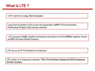
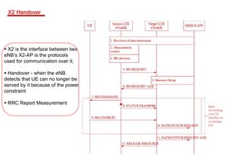
![What is LTE ?
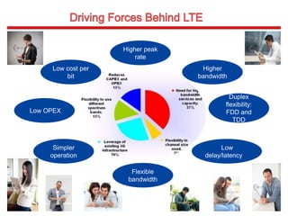
Driving Forces Behind LTE
LTE Vendor Ecosystem
LTE & 2G/3G Interworking Network Architecture
LTE Network Architecture - EPS
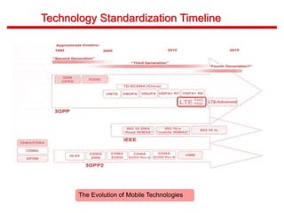
Technology Standardization Timeline
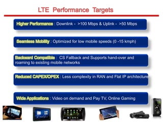
LTE Performance Targets
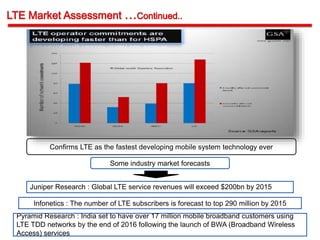
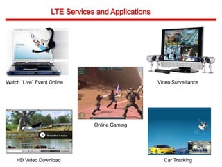
LTE Market Assessment
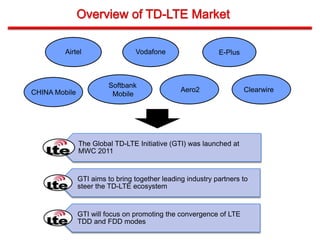
Overview of TD-LTE Market
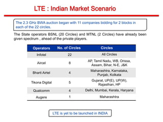
LTE Indian Market Scenario
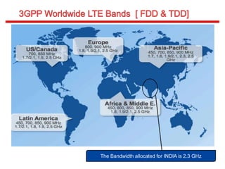
3GPP Worldwide LTE Bands [ FDD & TDD ]
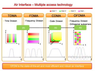
Radio Technology Options
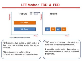
LTE Modes : TDD & FDD](https://image.slidesharecdn.com/lteppt-170531215118/85/4G-LTE-4-320.jpg)
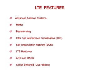
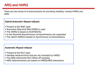
![***Source : www.gsacom.com
[Latest by 2011, Aug 31st ]
174 LTE network commitments in 64 countries
63 pre-commitments trials in 21 more
countries
26 commercial LTE networks launched
At least 93 LTE networks are expected to be
in commercial service by end 2012
237 operators in 85 countries are
investing in LTE](https://image.slidesharecdn.com/lteppt-170531215118/85/4G-LTE-12-320.jpg)
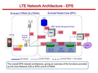
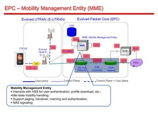
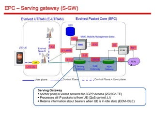
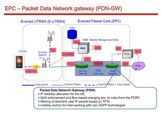
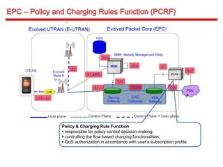
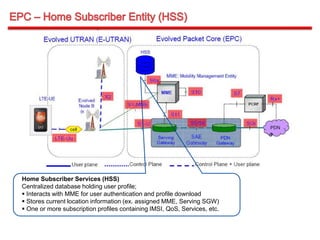
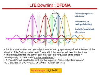
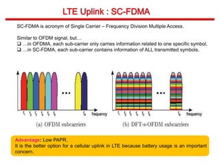


The document provides an overview of Long Term Evolution (LTE) technology. It discusses that LTE is the next generation mobile network standard that uses an all-IP flat network architecture. LTE networks employ OFDMA for the downlink and SC-FDMA for the uplink. Key performance targets of LTE include peak data rates of over 100 Mbps downlink and 50 Mbps uplink, low latency, and improved spectrum efficiency. The document also outlines the LTE network architecture including components like the eNodeB, MME, SGW, and PGW.


![5G Explained! A High Level Overview [Introduction]](https://cdn.slidesharecdn.com/ss_thumbnails/5gexplainedahighleveloverview-260119165306-cc137a3e-thumbnail.jpg?width=640&height=640&fit=bounds)


