Downloaded 668 times
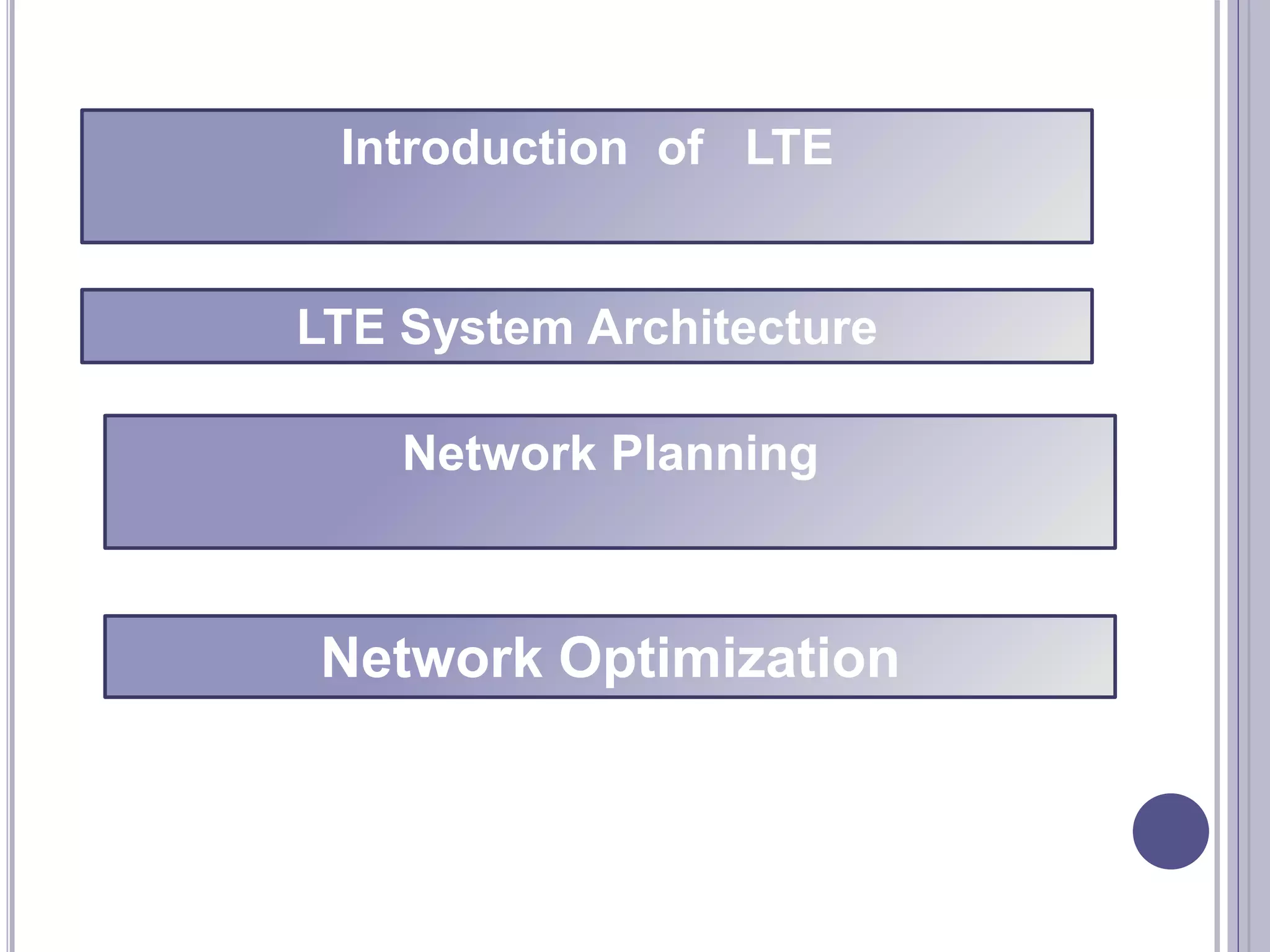
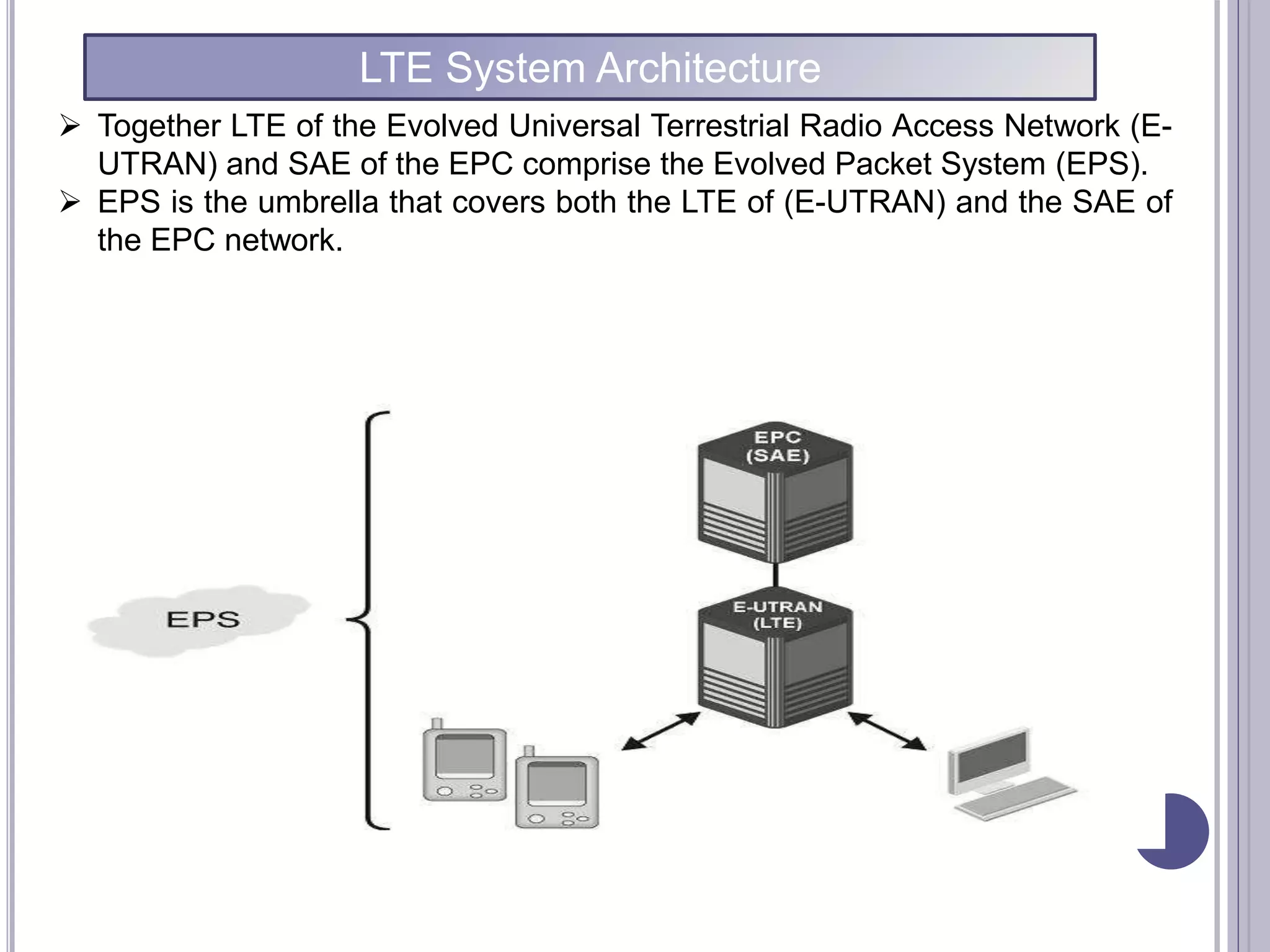
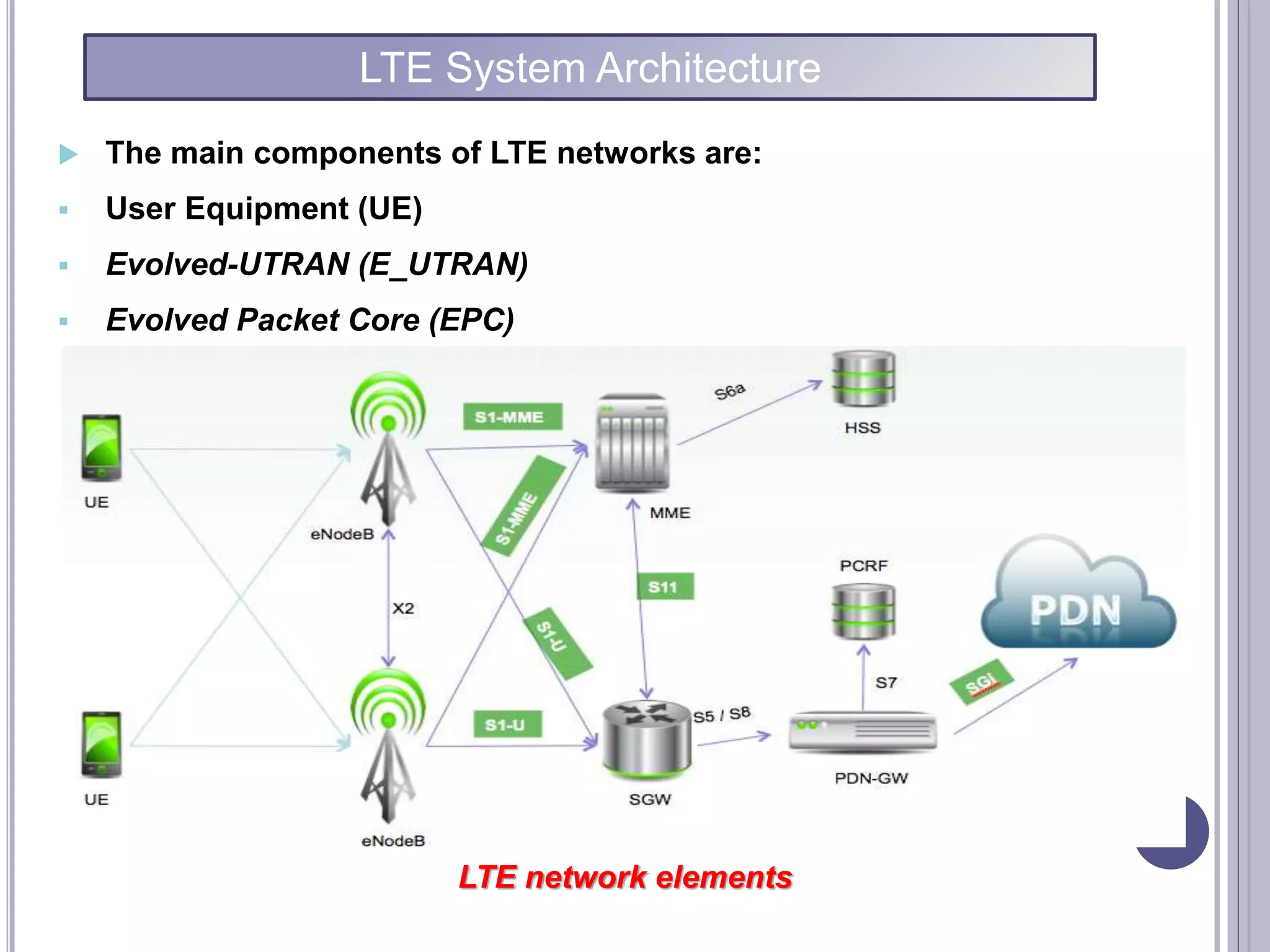
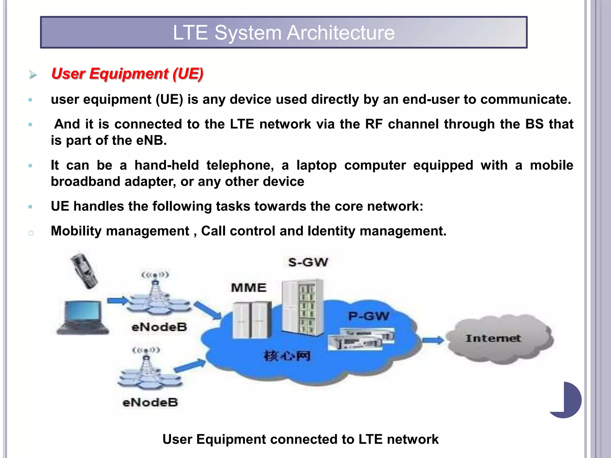
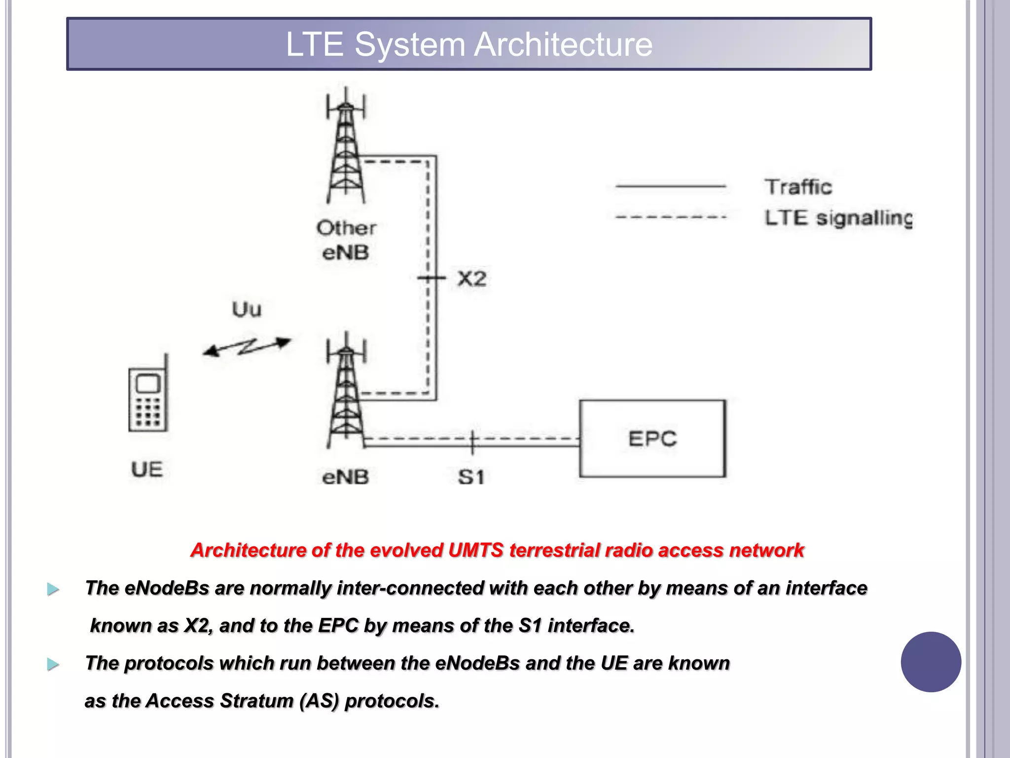
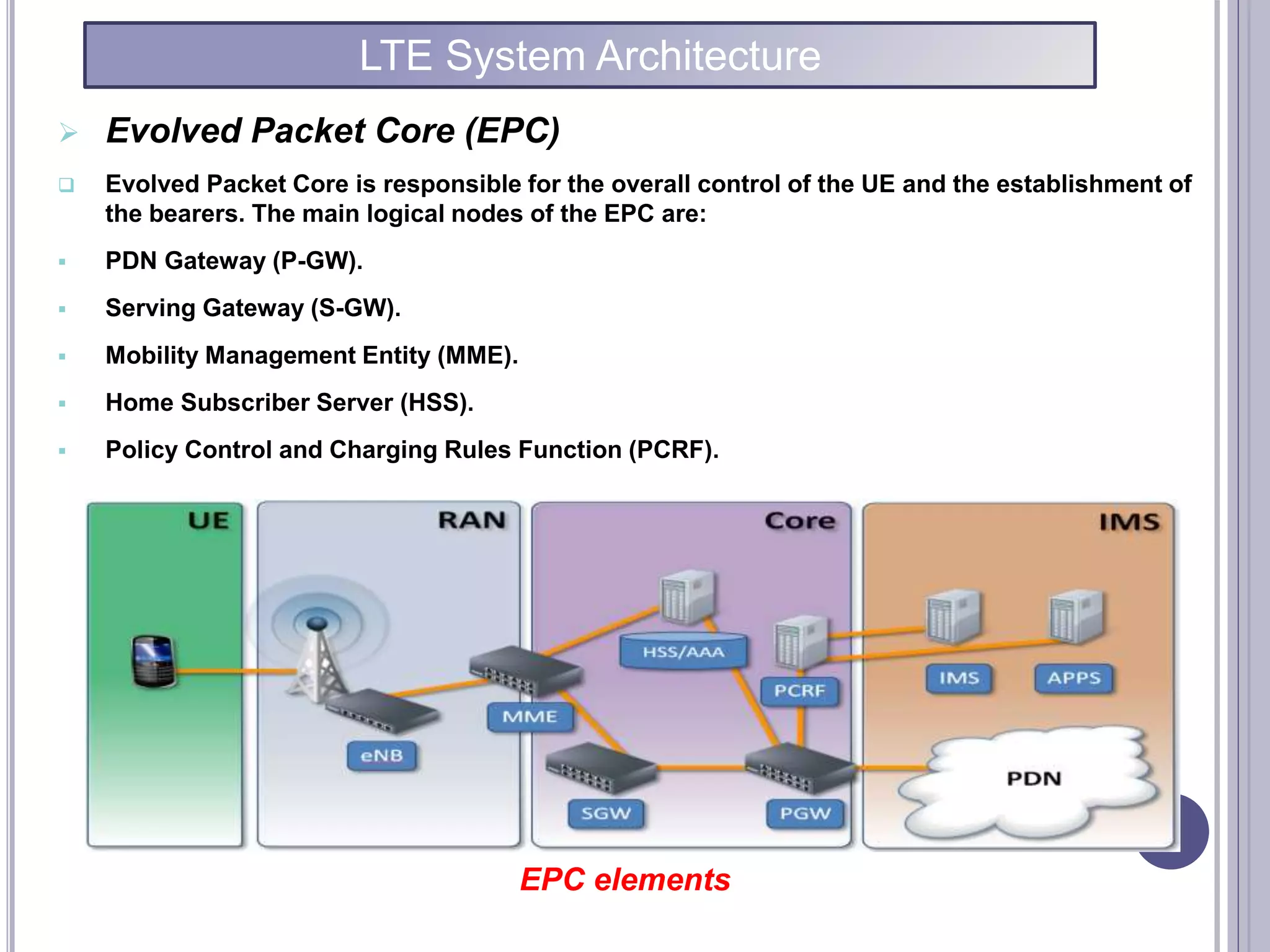

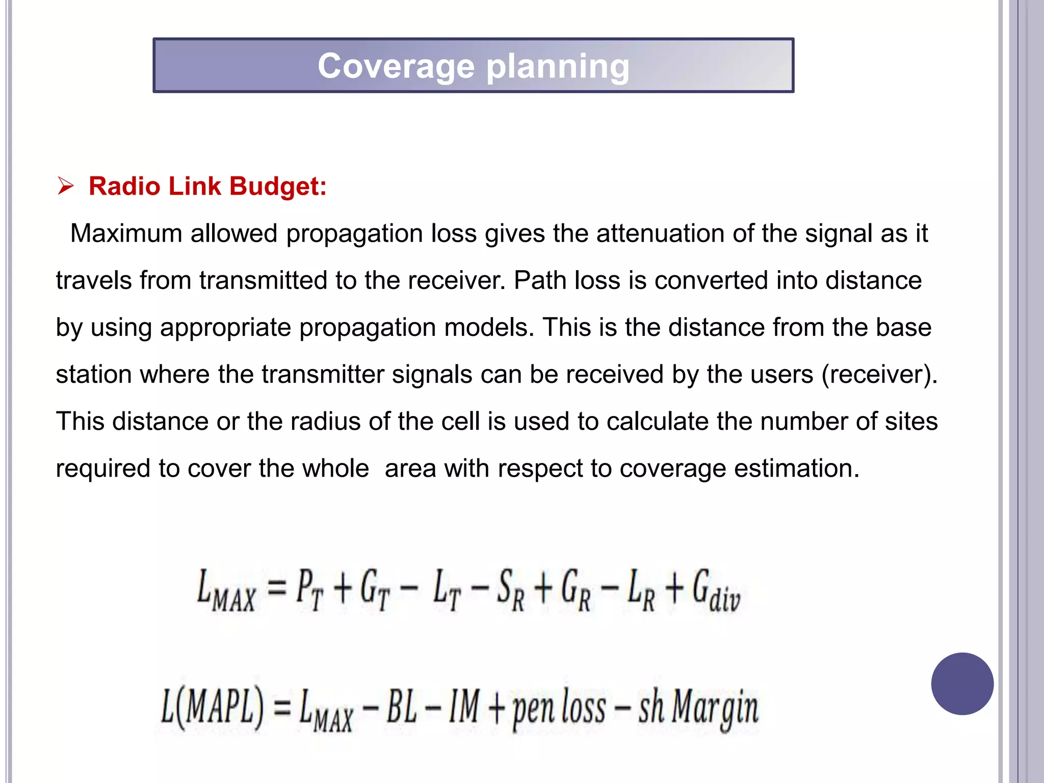

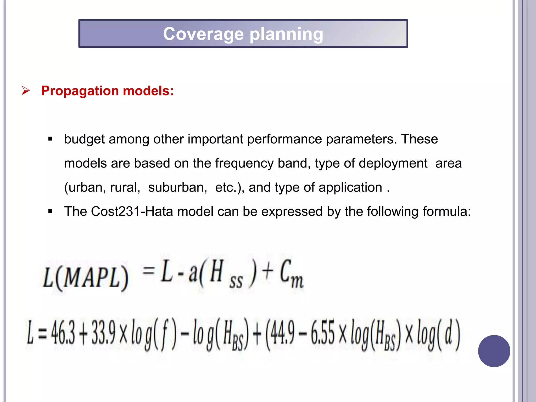
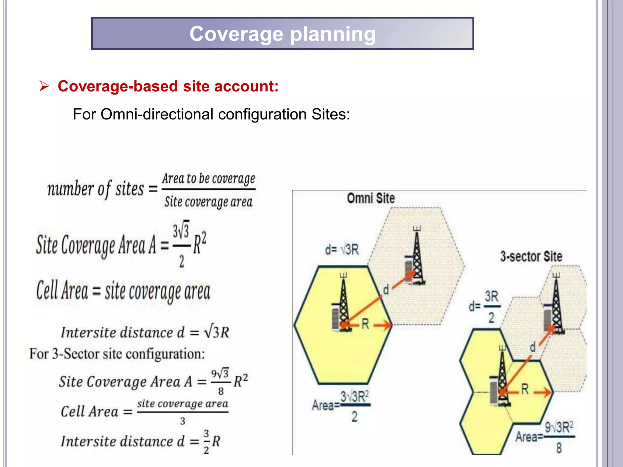
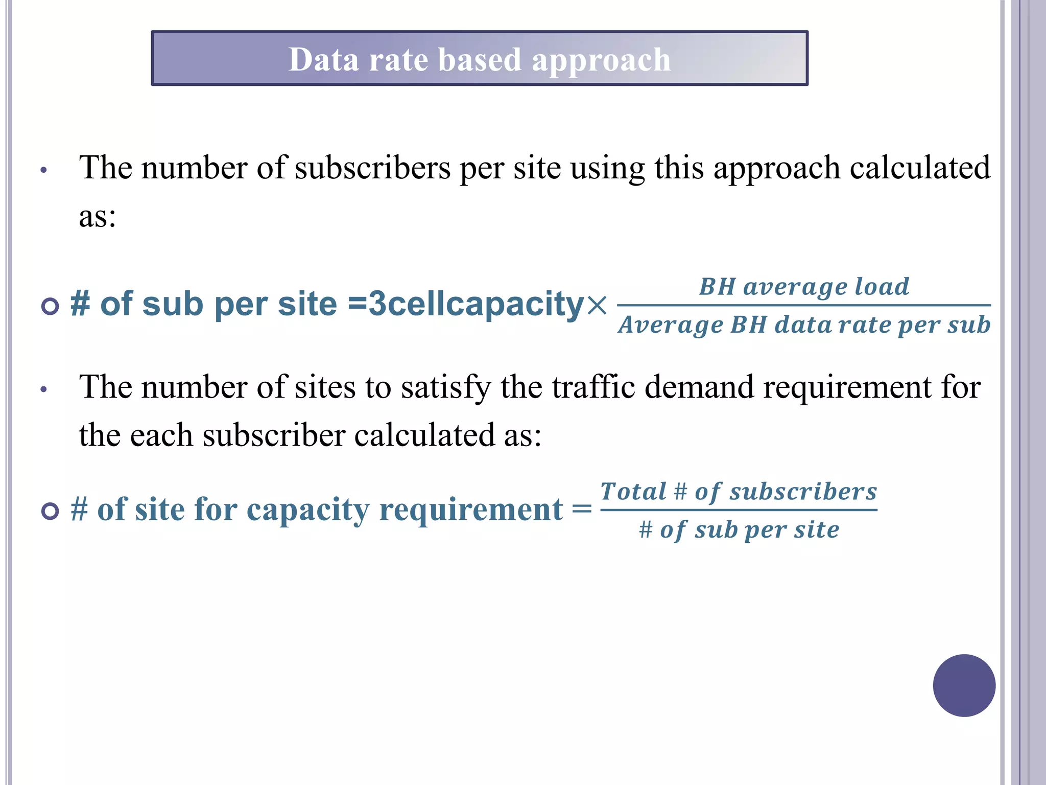
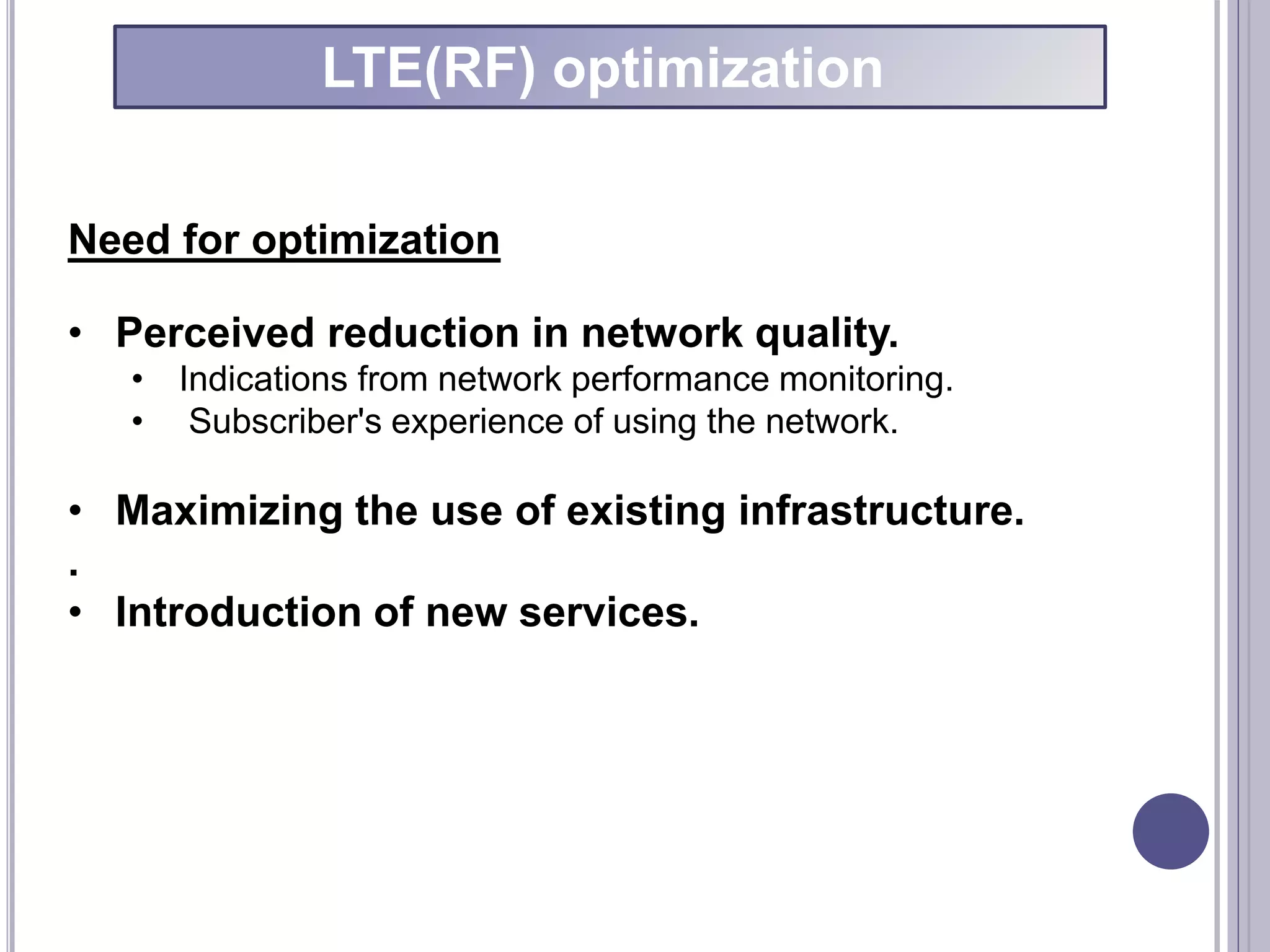

This document describes the design of an LTE network optimization project by a group of students from Taiz University. It includes an introduction to LTE, the network planning process, and LTE system architecture. The network planning section discusses coverage planning including link budget calculations and propagation models, as well as capacity planning considering factors like interference levels and supported modulation schemes. The document also provides an overview of LTE system architecture components including the user equipment, E-UTRAN, EPC, and functions of each. It concludes with a section on LTE radio frequency optimization methods.