Downloaded 348 times

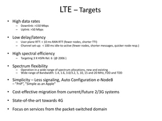
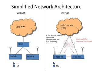
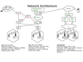
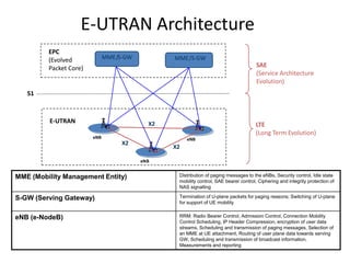
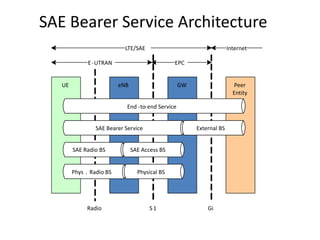
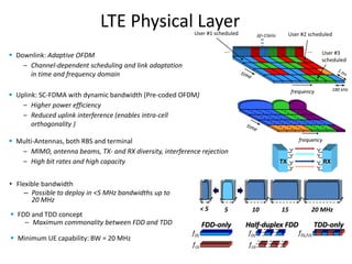
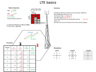
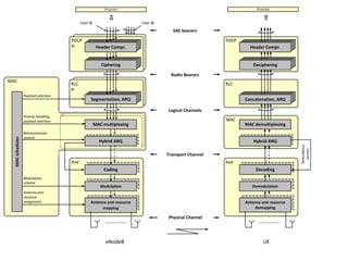
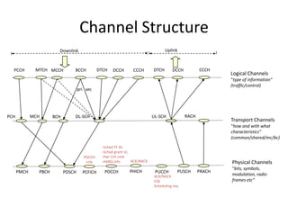
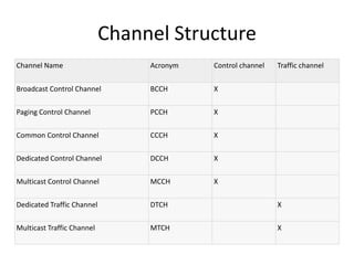
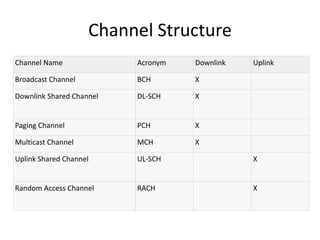
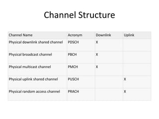

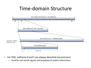
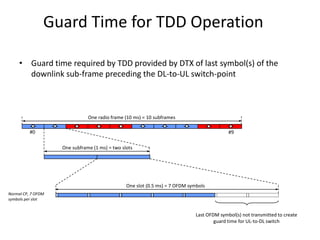


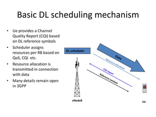

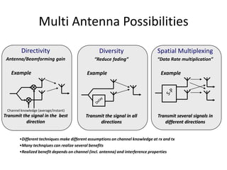

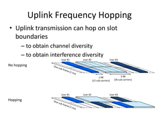
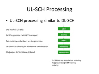

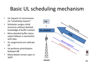

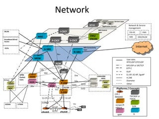


The document outlines the technical aspects and objectives of Long Term Evolution (LTE) including high data rates, low latency, high spectral efficiency, and spectrum flexibility. It details the architecture of LTE networks, the functionality of eNodeB, and the mechanisms for scheduling, control signaling, and resource allocation for both uplink and downlink transmissions. Additionally, it introduces various modulation schemes, channel structures, and the integration of different access and core network components to optimize wireless communication.


