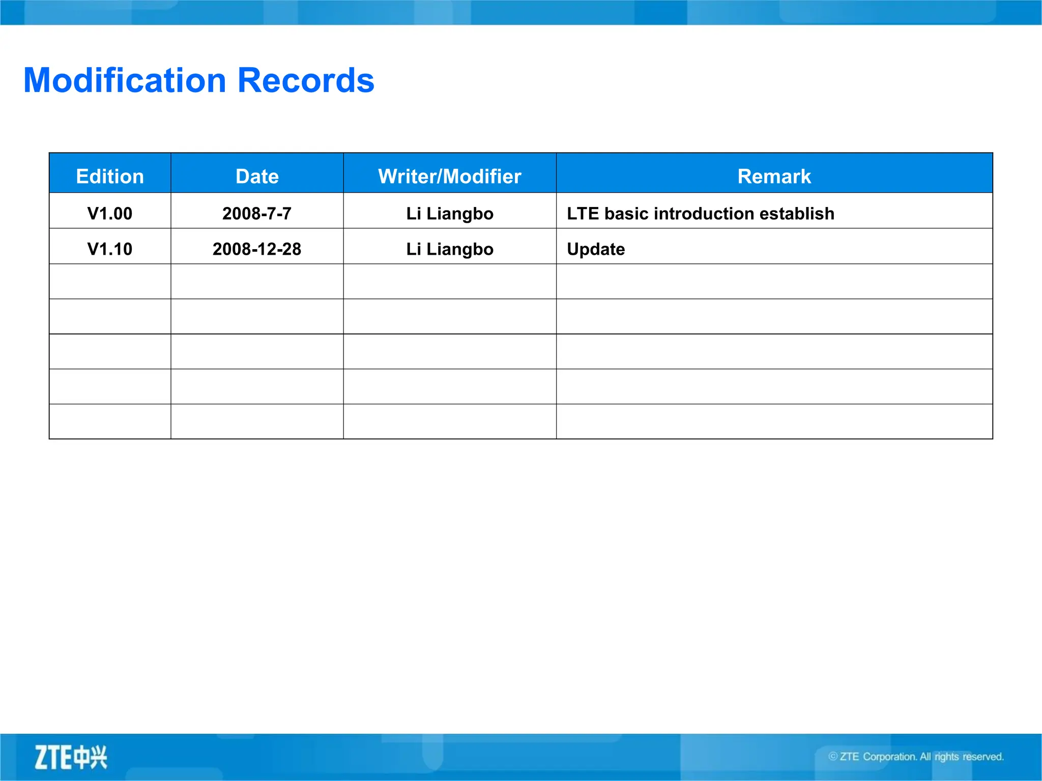
Modification Records
Edition DateWriter/Modifier Remark
V1.00 2008-7-7 Li Liangbo LTE basic introduction establish
V1.10 2008-12-28 Li Liangbo Update
3.
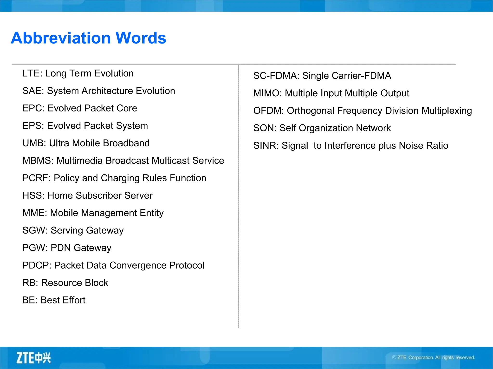
Abbreviation Words
LTE: LongTerm Evolution
SAE: System Architecture Evolution
EPC: Evolved Packet Core
EPS: Evolved Packet System
UMB: Ultra Mobile Broadband
MBMS: Multimedia Broadcast Multicast Service
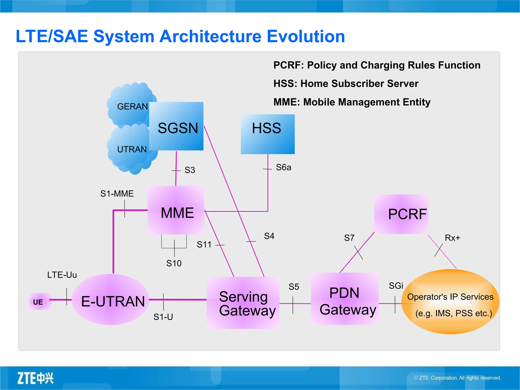
PCRF: Policy and Charging Rules Function
HSS: Home Subscriber Server
MME: Mobile Management Entity
SGW: Serving Gateway
PGW: PDN Gateway
PDCP: Packet Data Convergence Protocol
RB: Resource Block
BE: Best Effort
SC-FDMA: Single Carrier-FDMA
MIMO: Multiple Input Multiple Output
OFDM: Orthogonal Frequency Division Multiplexing
SON: Self Organization Network
SINR: Signal to Interference plus Noise Ratio
4.
Mobile TechnologyOverview
LTE Features & Performance
ZTE LTE Network Solution
5.
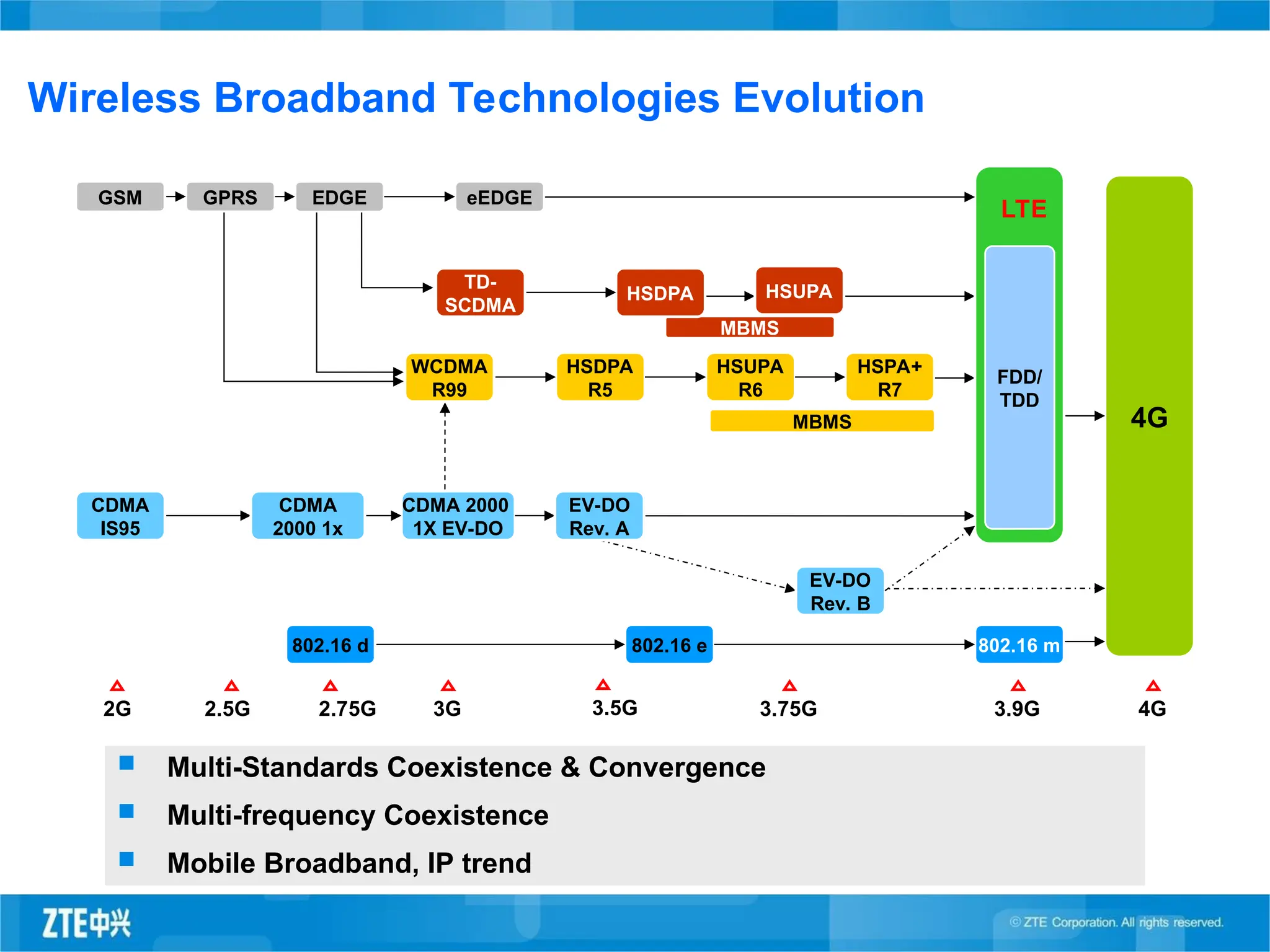
Wireless Broadband TechnologiesEvolution
Multi-Standards Coexistence & Convergence
Multi-frequency Coexistence
Mobile Broadband, IP trend
2G 2.5G 2.75G 3G 3.5G 3.75G 3.9G
GPRS EDGE eEDGE
HSDPA
R5
HSUPA
R6
MBMS 4G
MBMS
CDMA 2000
1X EV-DO
802.16 e 802.16 m
HSDPA
HSPA+
R7
FDD/
TDD
4G
GSM
TD-
SCDMA
WCDMA
R99
802.16 d
CDMA
IS95
CDMA
2000 1x
LTE
EV-DO
Rev. A
EV-DO
Rev. B
HSUPA
6.
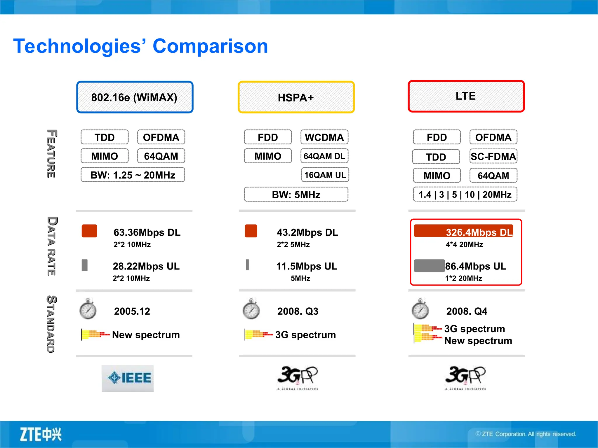
Technologies’ Comparison
F
F
EATURE
EATURE
D
D
ATA
RATE
ATA
RATE
S
S
TANDARD
TANDARD
HSPA+
FDD WCDMA
MIMO64QAM DL
BW: 5MHz
43.2Mbps DL
2*2 5MHz
11.5Mbps UL
5MHz
2008. Q3
3G spectrum
16QAM UL
LTE
FDD OFDMA
MIMO 64QAM
1.4 | 3 | 5 | 10 | 20MHz
326.4Mbps DL
4*4 20MHz
86.4Mbps UL
1*2 20MHz
2008. Q4
3G spectrum
New spectrum
SC-FDMA
TDD
802.16e (WiMAX)
TDD OFDMA
MIMO 64QAM
BW: 1.25 ~ 20MHz
63.36Mbps DL
2*2 10MHz
28.22Mbps UL
2*2 10MHz
2005.12
New spectrum
7.
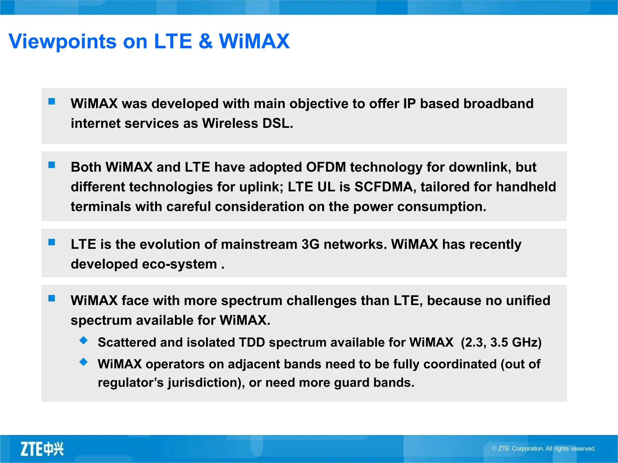
Viewpoints on LTE& WiMAX
WiMAX was developed with main objective to offer IP based broadband
internet services as Wireless DSL.
Both WiMAX and LTE have adopted OFDM technology for downlink, but
different technologies for uplink; LTE UL is SCFDMA, tailored for handheld
terminals with careful consideration on the power consumption.
LTE is the evolution of mainstream 3G networks. WiMAX has recently
developed eco-system .
WiMAX face with more spectrum challenges than LTE, because no unified
spectrum available for WiMAX.
Scattered and isolated TDD spectrum available for WiMAX (2.3, 3.5 GHz)
WiMAX operators on adjacent bands need to be fully coordinated (out of
regulator’s jurisdiction), or need more guard bands.
8.
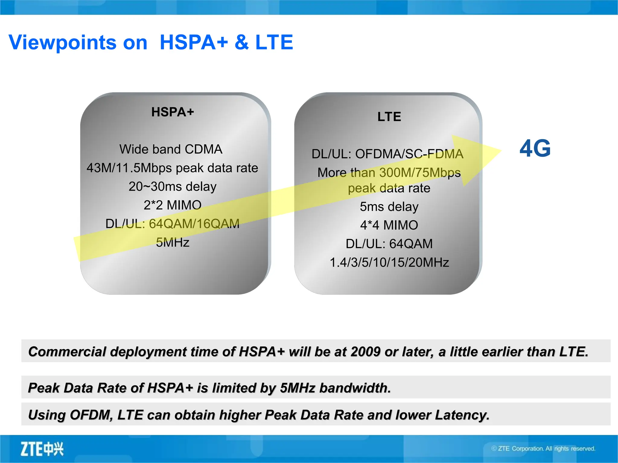
Commercial deployment timeof HSPA+ will be at 2009 or later, a little earlier than LTE.
Commercial deployment time of HSPA+ will be at 2009 or later, a little earlier than LTE.
Viewpoints on HSPA+ & LTE
LTE
DL/UL: OFDMA/SC-FDMA
More than 300M/75Mbps
peak data rate
5ms delay
4*4 MIMO
DL/UL: 64QAM
1.4/3/5/10/15/20MHz
HSPA+
Wide band CDMA
43M/11.5Mbps peak data rate
20~30ms delay
2*2 MIMO
DL/UL: 64QAM/16QAM
5MHz
4G
Peak Data Rate of HSPA+ is limited by 5MHz bandwidth.
Peak Data Rate of HSPA+ is limited by 5MHz bandwidth.
Using OFDM, LTE can obtain higher Peak Data Rate and lower Latency.
Using OFDM, LTE can obtain higher Peak Data Rate and lower Latency.
9.
2005 2006 20072008 2009
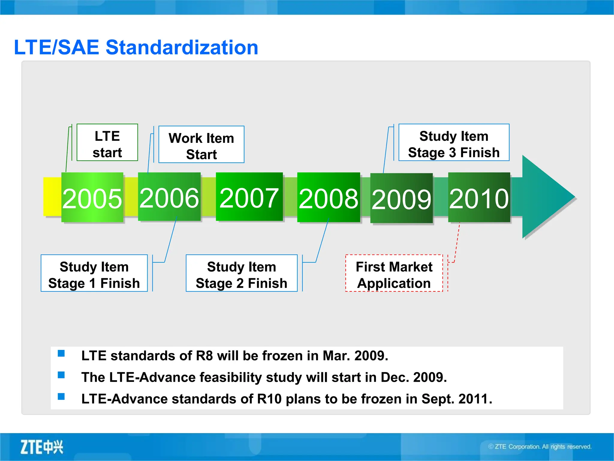
LTE/SAE Standardization
LTE
start
Work Item
Start
Study Item
Stage 1 Finish
Study Item
Stage 3 Finish
Study Item
Stage 2 Finish
First Market
Application
LTE standards of R8 will be frozen in Mar. 2009.
The LTE-Advance feasibility study will start in Dec. 2009.
LTE-Advance standards of R10 plans to be frozen in Sept. 2011.
2010
10.
Mobile TechnologyOverview
LTE Features & Performance
ZTE LTE Network Solution
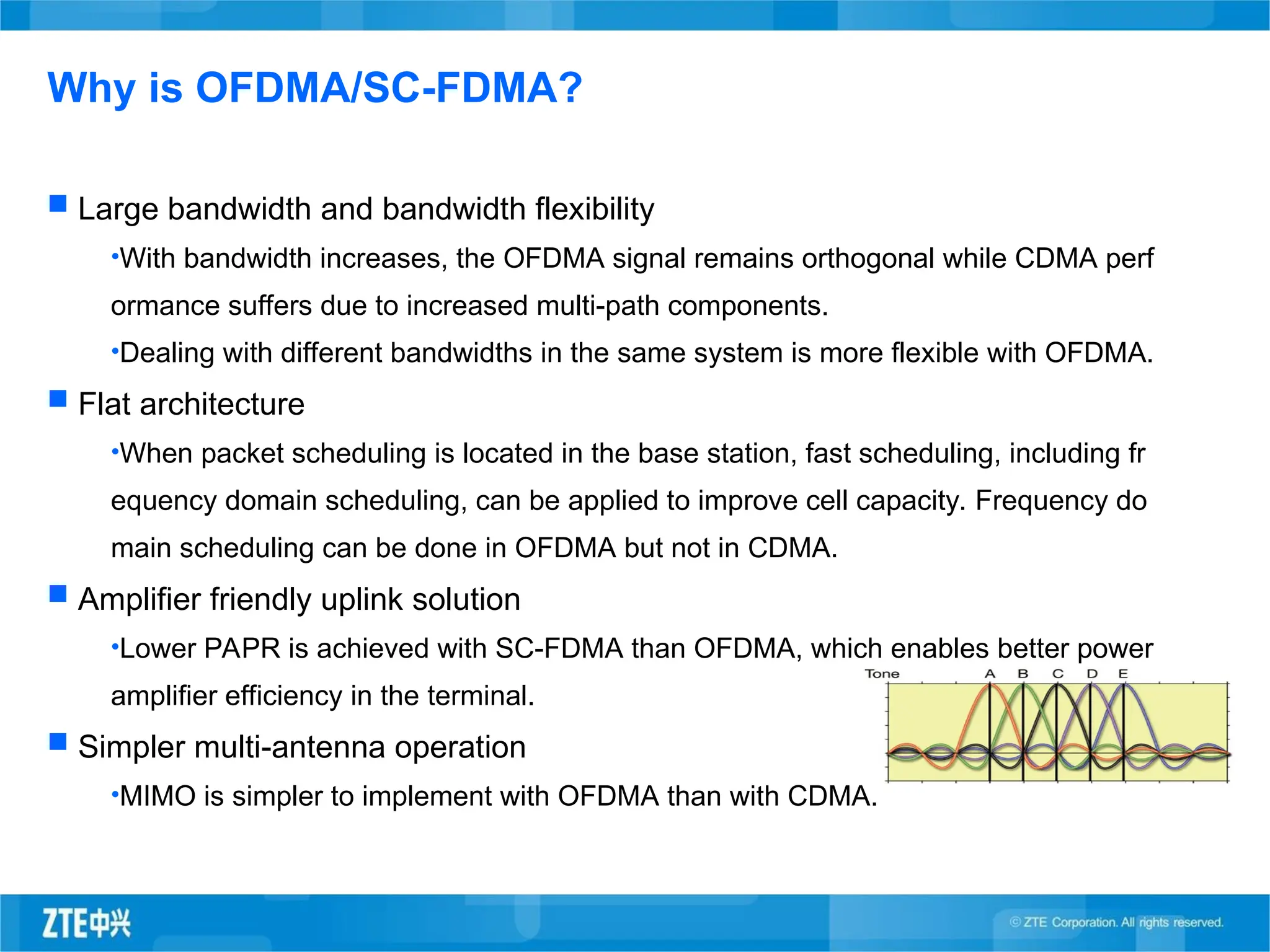
Large bandwidthand bandwidth flexibility
•With bandwidth increases, the OFDMA signal remains orthogonal while CDMA perf
ormance suffers due to increased multi-path components.
•Dealing with different bandwidths in the same system is more flexible with OFDMA.
Flat architecture
•When packet scheduling is located in the base station, fast scheduling, including fr
equency domain scheduling, can be applied to improve cell capacity. Frequency do
main scheduling can be done in OFDMA but not in CDMA.
Amplifier friendly uplink solution
•Lower PAPR is achieved with SC-FDMA than OFDMA, which enables better power
amplifier efficiency in the terminal.
Simpler multi-antenna operation
•MIMO is simpler to implement with OFDMA than with CDMA.
Why is OFDMA/SC-FDMA?
20.
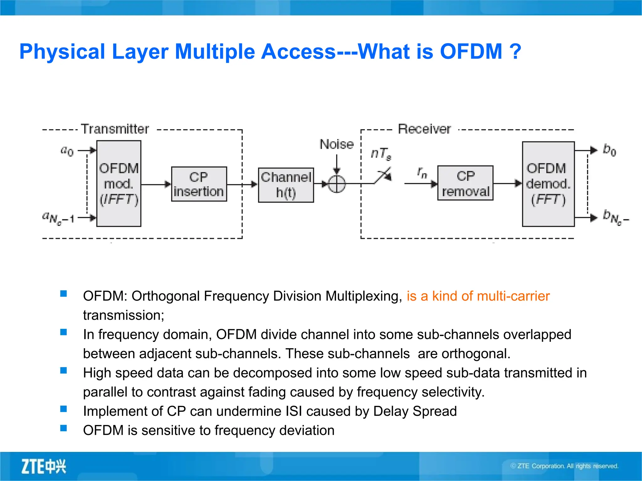
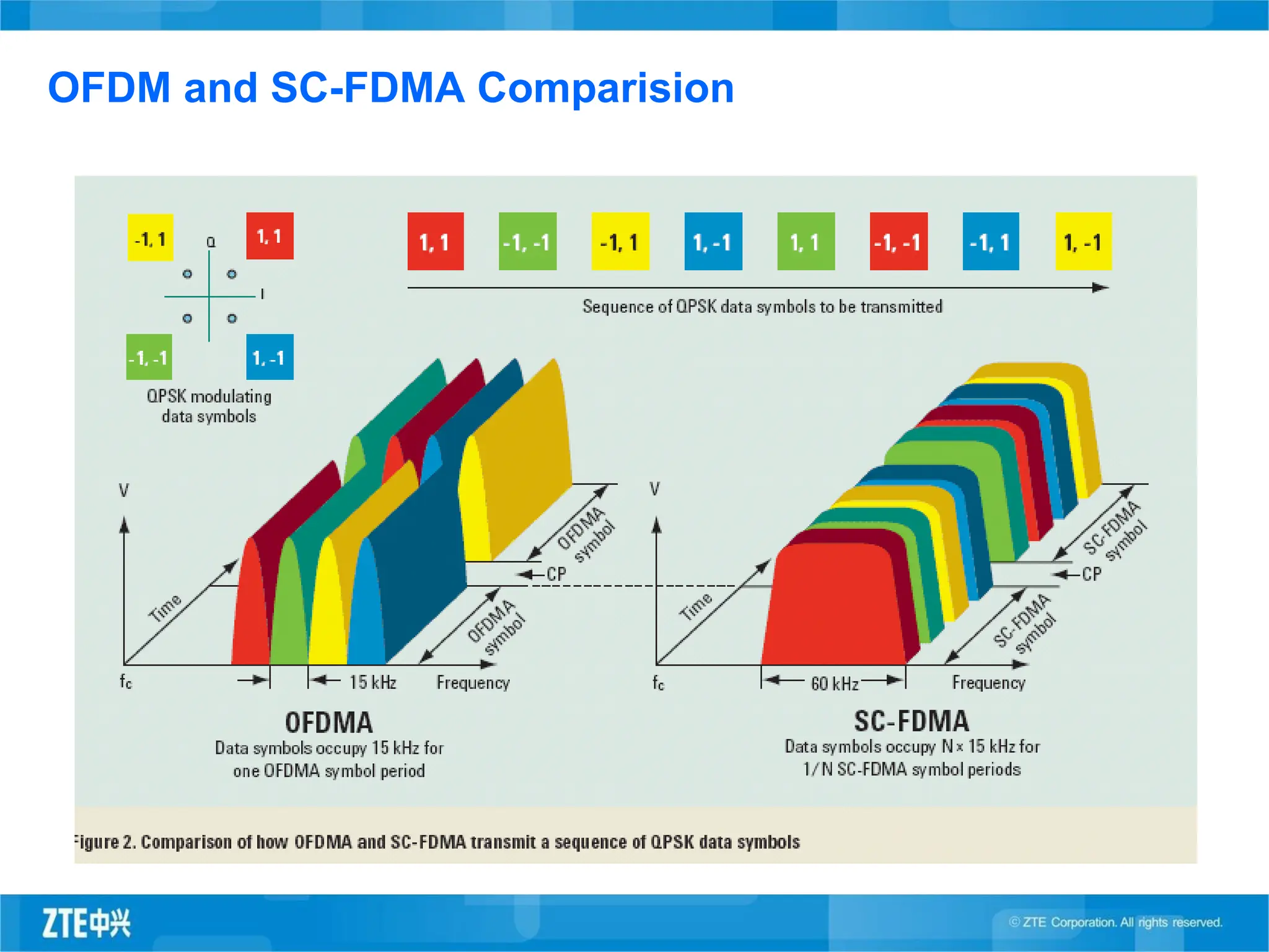
Physical Layer MultipleAccess---What is OFDM ?
OFDM: Orthogonal Frequency Division Multiplexing, is a kind of multi-carrier
transmission;
In frequency domain, OFDM divide channel into some sub-channels overlapped
between adjacent sub-channels. These sub-channels are orthogonal.
High speed data can be decomposed into some low speed sub-data transmitted in
parallel to contrast against fading caused by frequency selectivity.
Implement of CP can undermine ISI caused by Delay Spread
OFDM is sensitive to frequency deviation
21.
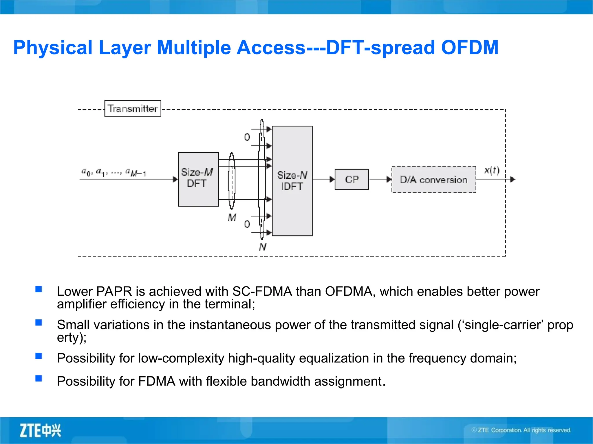
Physical Layer MultipleAccess---DFT-spread OFDM
Lower PAPR is achieved with SC-FDMA than OFDMA, which enables better power
amplifier efficiency in the terminal;
Small variations in the instantaneous power of the transmitted signal (‘single-carrier’ prop
erty);
Possibility for low-complexity high-quality equalization in the frequency domain;
Possibility for FDMA with flexible bandwidth assignment.
22.
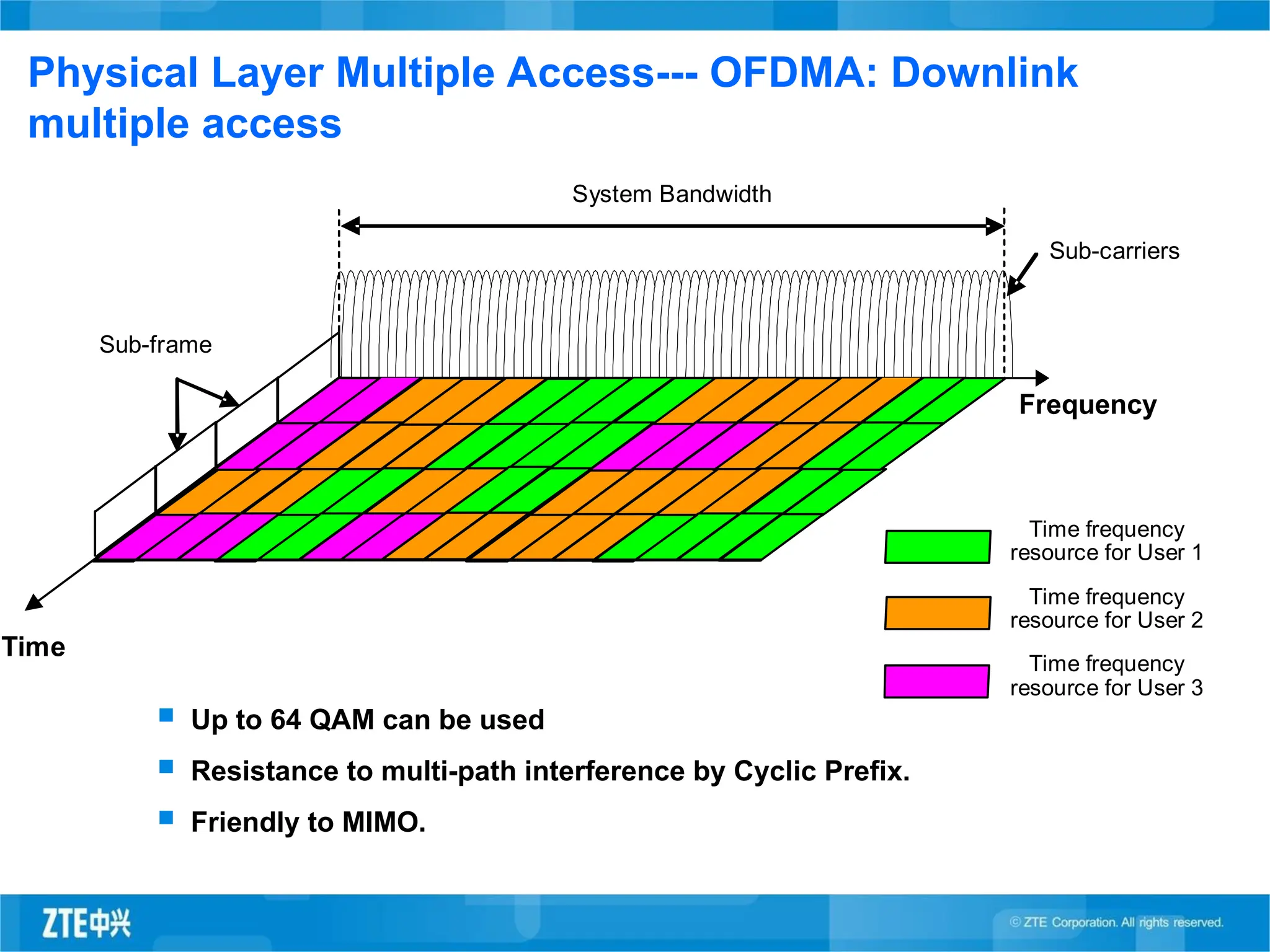
Physical Layer MultipleAccess--- OFDMA: Downlink
multiple access
Up to 64 QAM can be used
Resistance to multi-path interference by Cyclic Prefix.
Friendly to MIMO.
Sub-carriers
Sub-frame
Frequency
Time
Time frequency
resource for User 1
Time frequency
resource for User 2
Time frequency
resource for User 3
System Bandwidth
23.
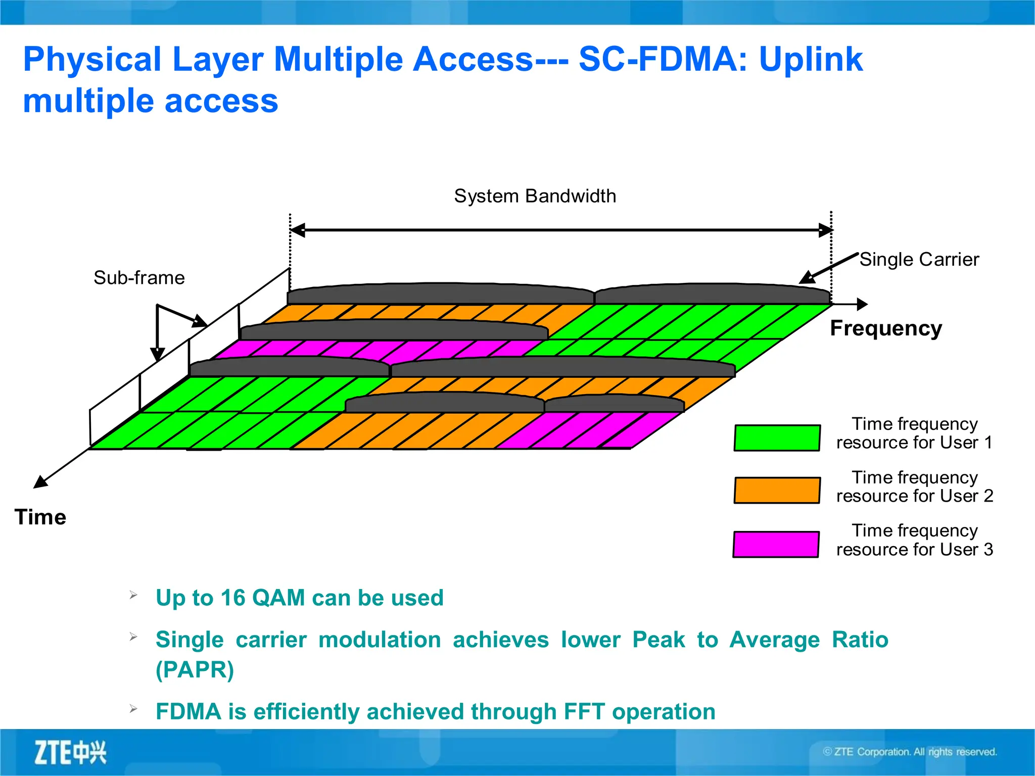
Physical Layer MultipleAccess--- SC-FDMA: Uplink
multiple access
Up to 16 QAM can be used
Single carrier modulation achieves lower Peak to Average Ratio
(PAPR)
FDMA is efficiently achieved through FFT operation
0
Single Carrier
Sub-frame
Frequency
Time
Time frequency
resource for User 1
Time frequency
resource for User 2
Time frequency
resource for User 3
System Bandwidth
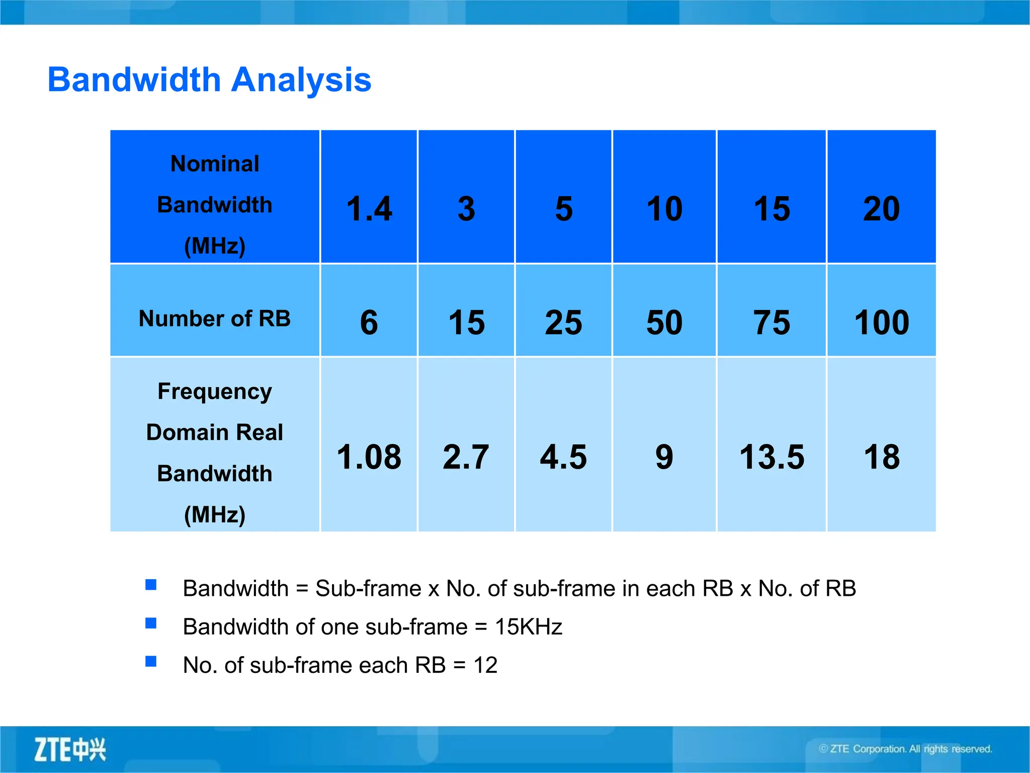
Bandwidth Analysis
Bandwidth= Sub-frame x No. of sub-frame in each RB x No. of RB
Bandwidth of one sub-frame = 15KHz
No. of sub-frame each RB = 12
Nominal
Bandwidth
(MHz)
1.4 3 5 10 15 20
Number of RB 6 15 25 50 75 100
Frequency
Domain Real
Bandwidth
(MHz)
1.08 2.7 4.5 9 13.5 18
27.
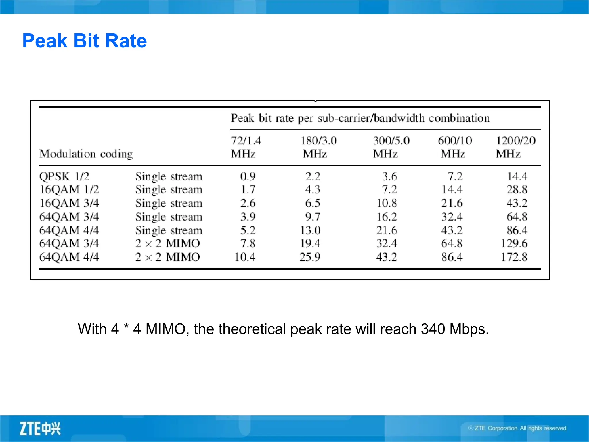
Peak Bit Rate
With4 * 4 MIMO, the theoretical peak rate will reach 340 Mbps.
28.
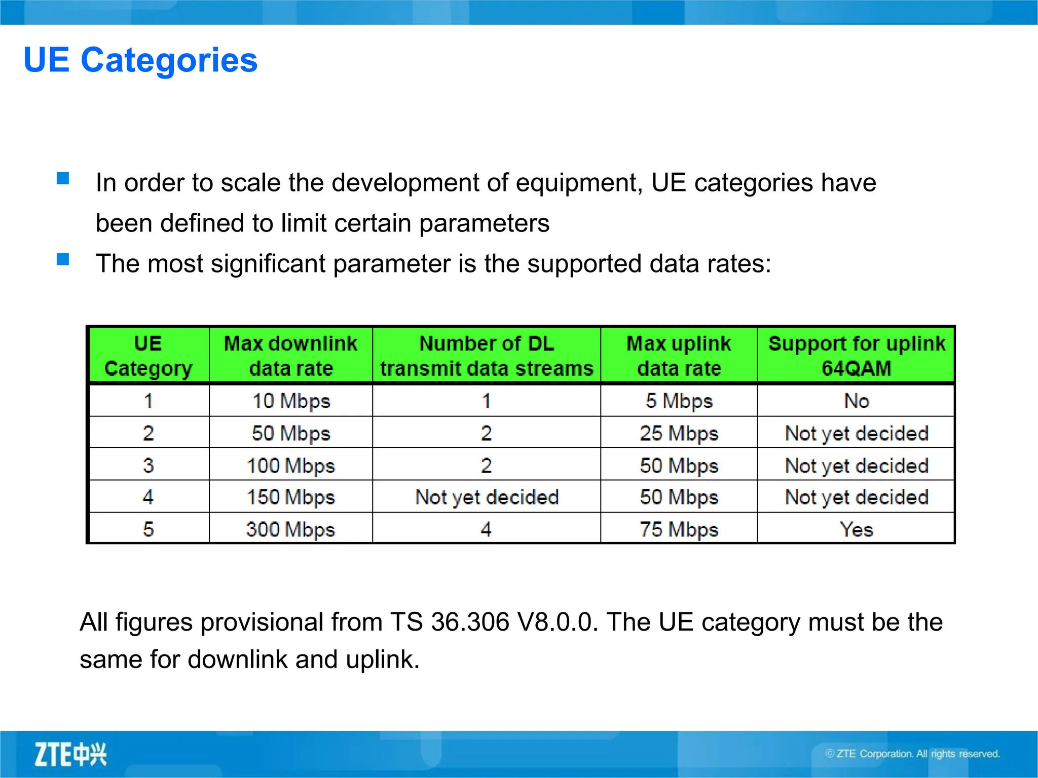
UE Categories
Inorder to scale the development of equipment, UE categories have
been defined to limit certain parameters
The most significant parameter is the supported data rates:
All figures provisional from TS 36.306 V8.0.0. The UE category must be the
same for downlink and uplink.
29.
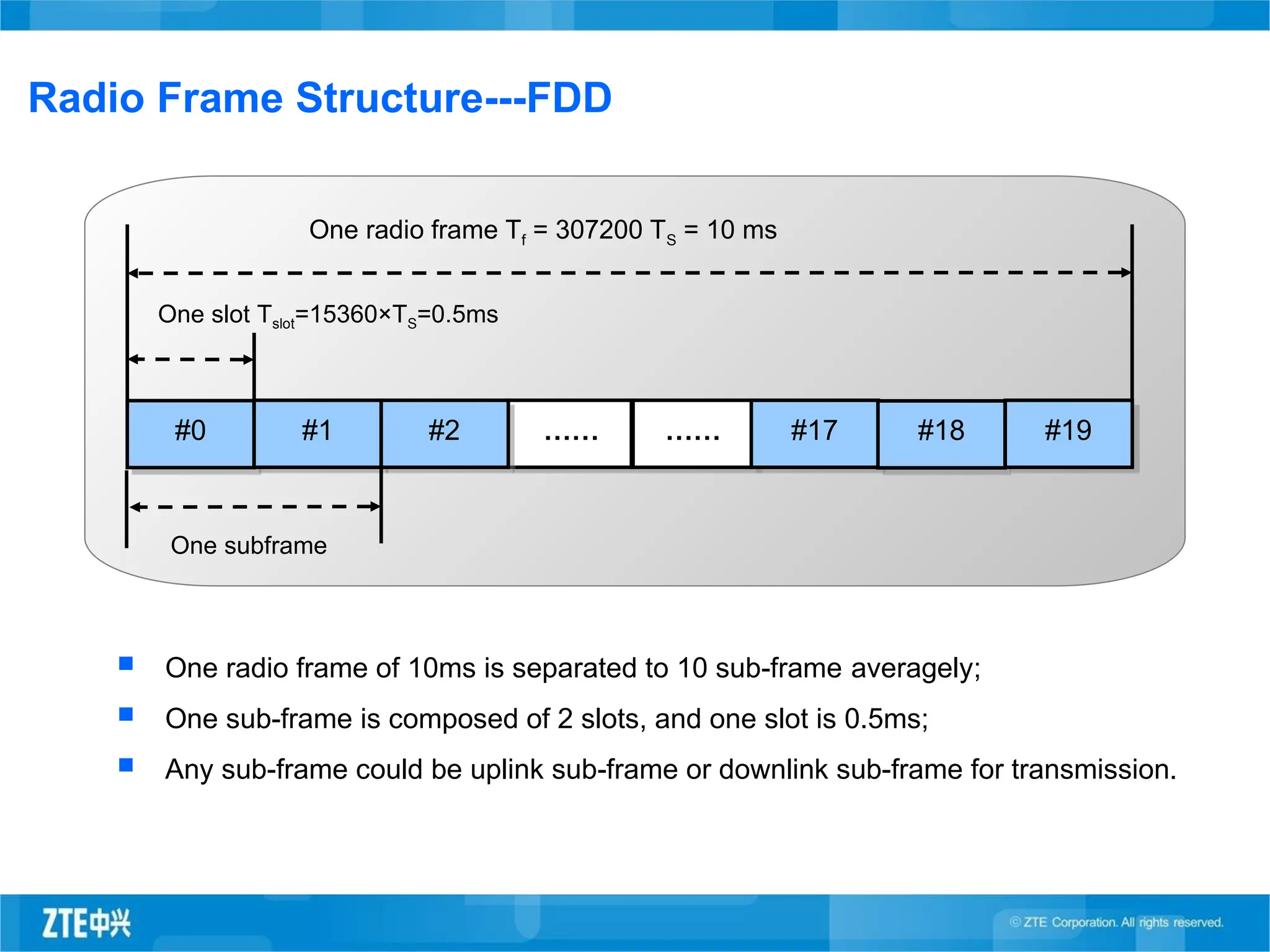
Radio Frame Structure---FDD
One radio frame of 10ms is separated to 10 sub-frame averagely;
One sub-frame is composed of 2 slots, and one slot is 0.5ms;
Any sub-frame could be uplink sub-frame or downlink sub-frame for transmission.
#0
One radio frame Tf = 307200 TS = 10 ms
One slot Tslot=15360×TS=0.5ms
#1
One subframe
…… ……
#2 #17 #18 #19
30.
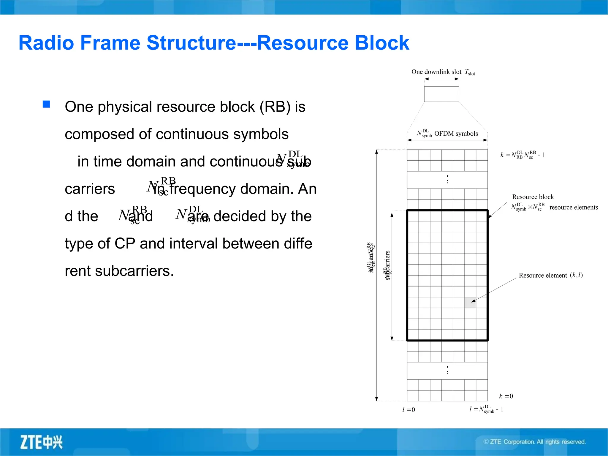
Radio Frame Structure---ResourceBlock
DL
symb
N OFDM symbols
One downlink slot slot
T
0
l 1
DL
symb
N
l
RB
sc
DL
RB
N
N
subcarriers
RB
sc
N
subcarriers
RB
sc
DL
symb N
N
Resource block
resource elements
Resource element )
,
( l
k
0
k
1
RB
sc
DL
RB
N
N
k
One physical resource block (RB) is
composed of continuous symbols
in time domain and continuous sub
carriers in frequency domain. An
d the and are decided by the
type of CP and interval between diffe
rent subcarriers.
DL
symb
N
RB
sc
N
DL
symb
N
RB
sc
N
31.
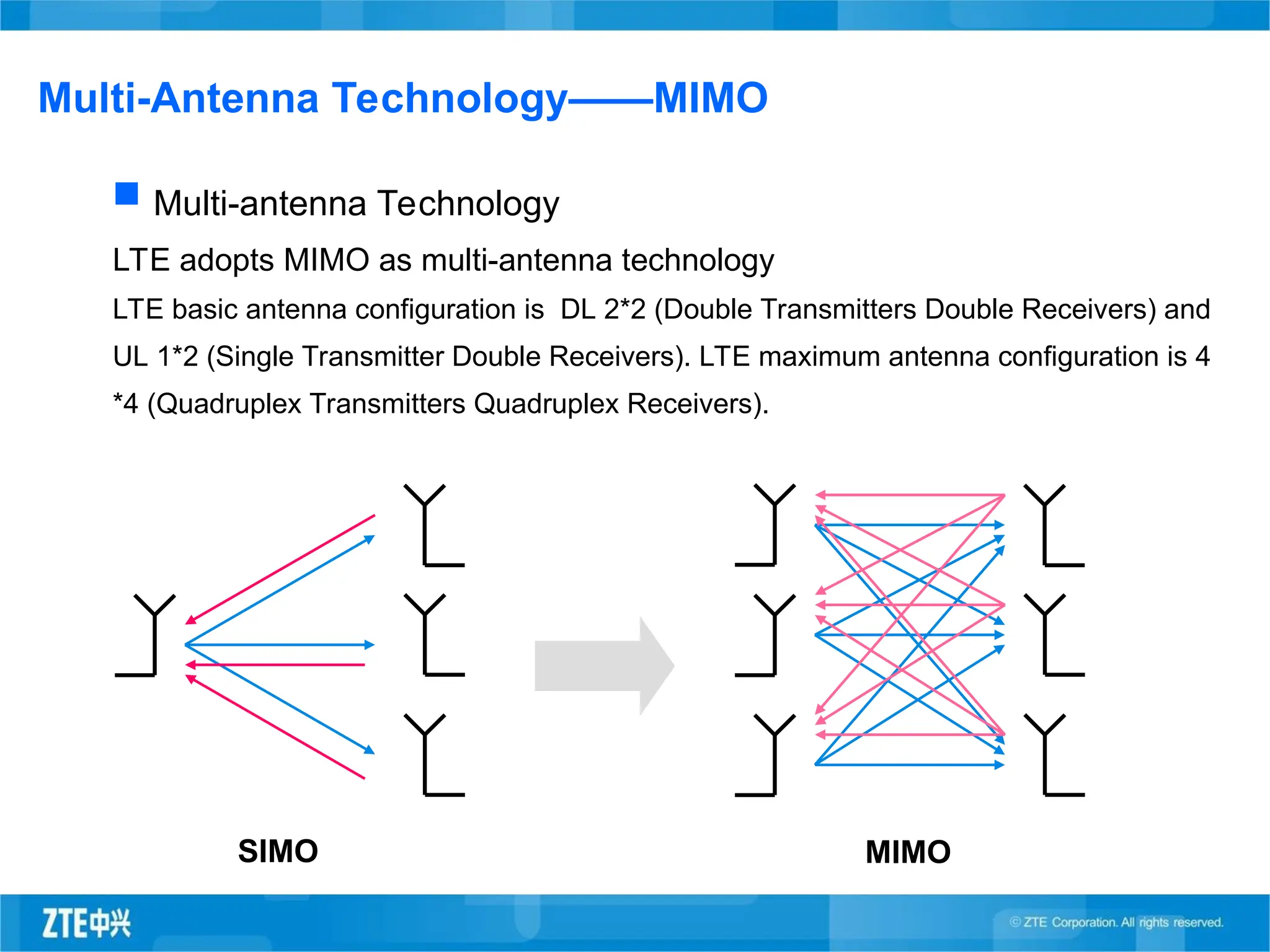
Multi-Antenna Technology——MIMO
Multi-antennaTechnology
LTE adopts MIMO as multi-antenna technology
LTE basic antenna configuration is DL 2*2 (Double Transmitters Double Receivers) and
UL 1*2 (Single Transmitter Double Receivers). LTE maximum antenna configuration is 4
*4 (Quadruplex Transmitters Quadruplex Receivers).
SIMO MIMO
32.
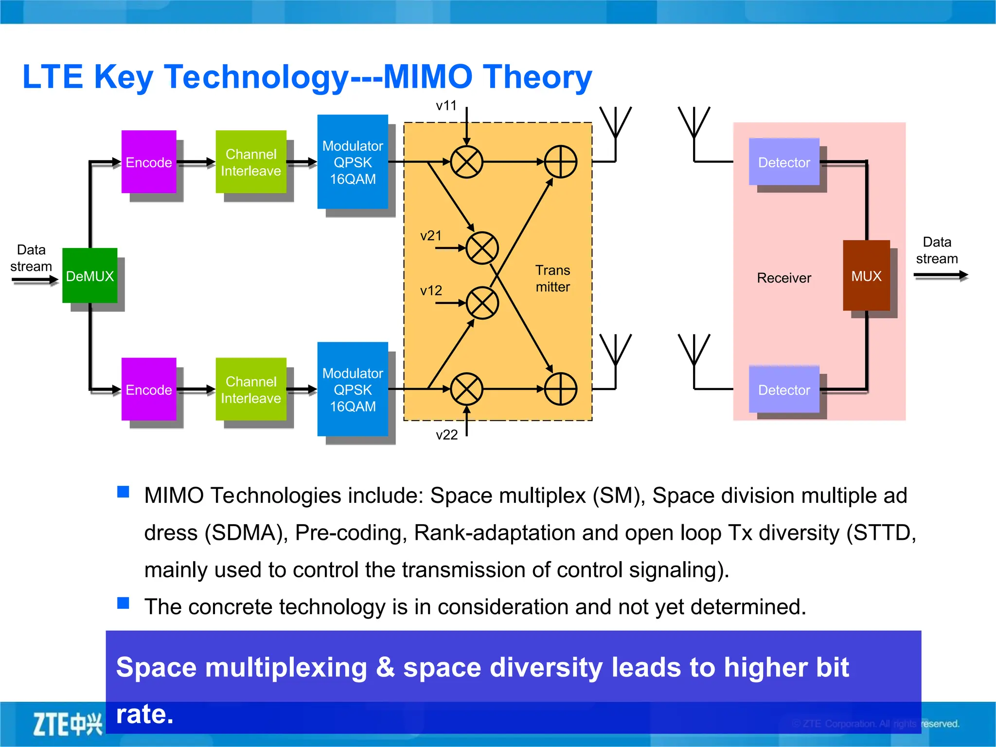
LTE Key Technology---MIMOTheory
Receiver
Data
stream
Encode
Encode
Channel
Interleave
Channel
Interleave
Modulator
QPSK
16QAM
Modulator
QPSK
16QAM
Detector
Detector
MUX
Data
stream
v12
v21
v11
v22
Trans
mitter
DeMUX
MIMO Technologies include: Space multiplex (SM), Space division multiple ad
dress (SDMA), Pre-coding, Rank-adaptation and open loop Tx diversity (STTD,
mainly used to control the transmission of control signaling).
The concrete technology is in consideration and not yet determined.
Space multiplexing & space diversity leads to higher bit
rate.
33.
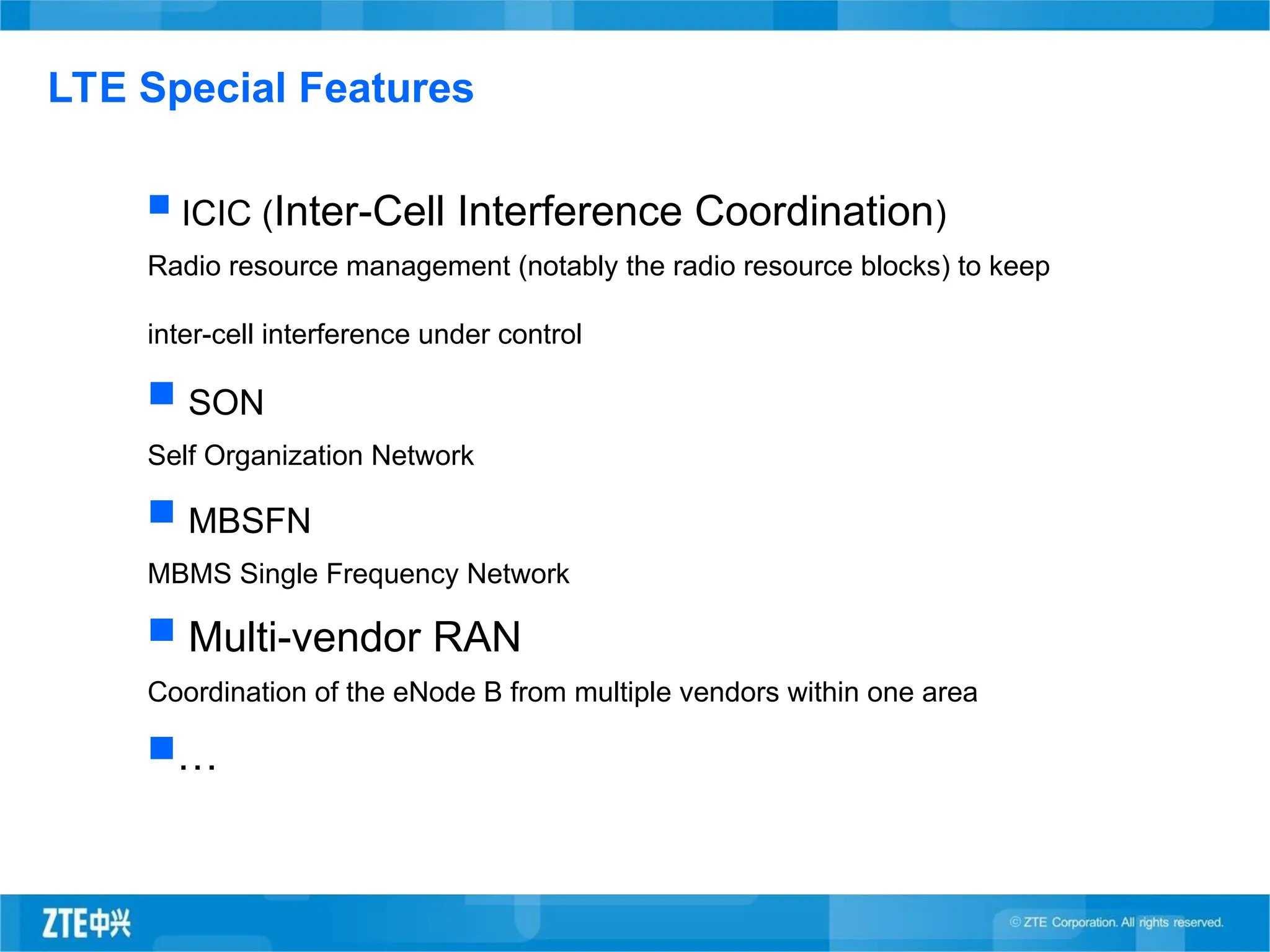
ICIC (Inter-CellInterference Coordination)
Radio resource management (notably the radio resource blocks) to keep
inter-cell interference under control
SON
Self Organization Network
MBSFN
MBMS Single Frequency Network
Multi-vendor RAN
Coordination of the eNode B from multiple vendors within one area
…
LTE Special Features
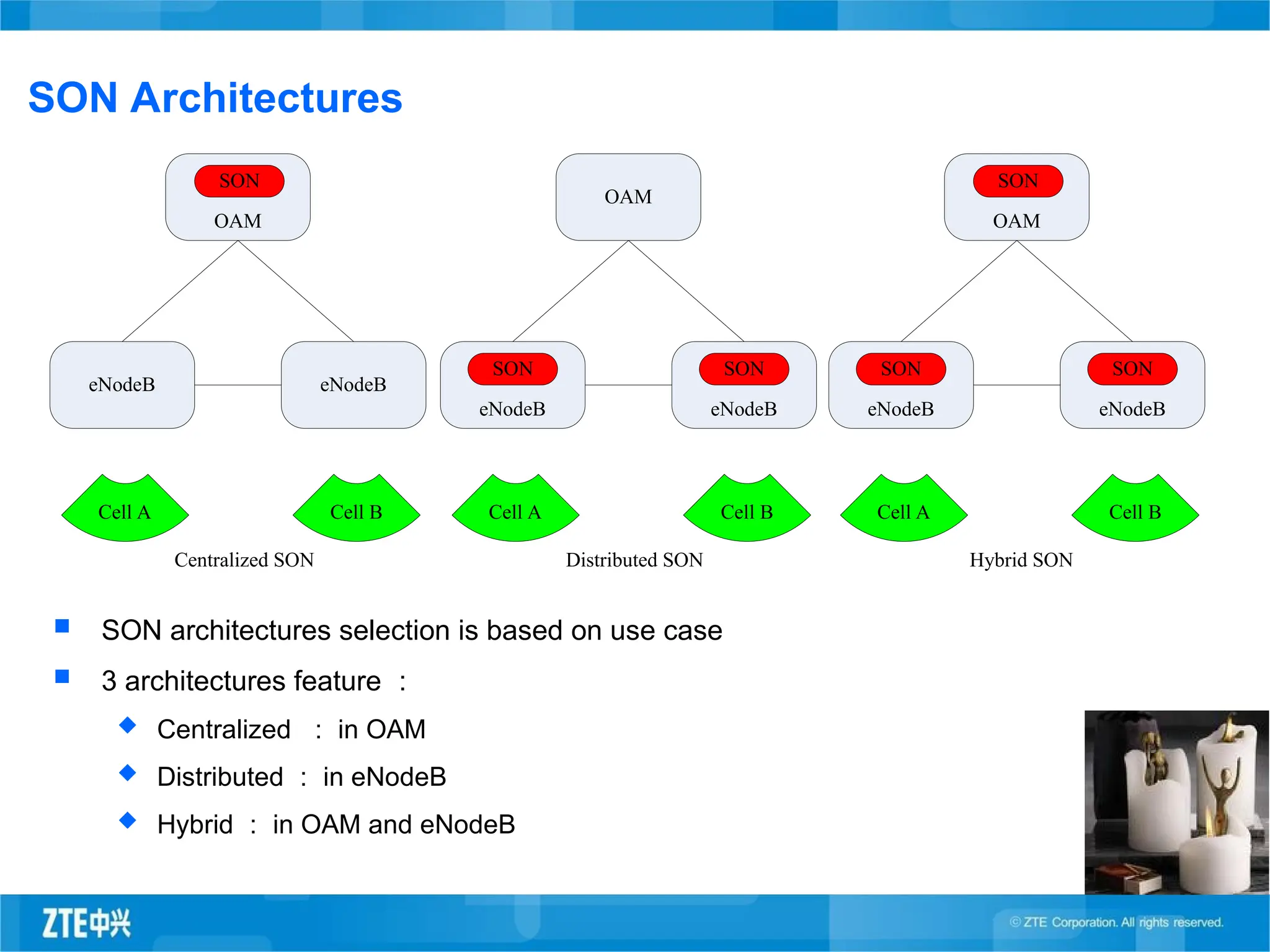
SON Architectures
SONarchitectures selection is based on use case
3 architectures feature :
Centralized : in OAM
Distributed : in eNodeB
Hybrid : in OAM and eNodeB
OAM
SON
eNodeB eNodeB
Cell A Cell B
OAM
eNodeB
SON
eNodeB
SON
Cell A Cell B
OAM
SON
eNodeB
SON
eNodeB
SON
Cell A Cell B
Centralized SON Distributed SON Hybrid SON
36.
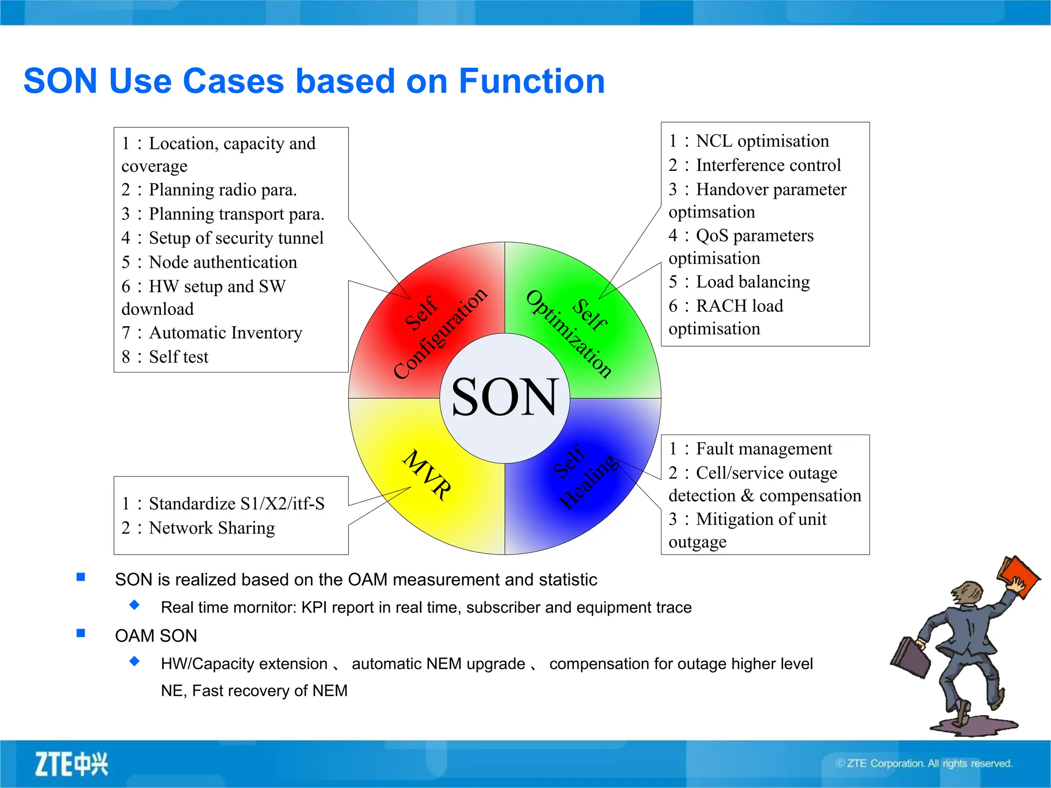
SON Use Casesbased on Function
SON is realized based on the OAM measurement and statistic
Real time mornitor: KPI report in real time, subscriber and equipment trace
OAM SON
HW/Capacity extension 、 automatic NEM upgrade 、 compensation for outage higher level
NE, Fast recovery of NEM
S
e
l
f
C
o
n
f
i
g
u
r
a
t
i
o
n
S
e
l
f
O
p
t
i
m
i
z
a
t
i
o
n
S
e
l
f
H
e
a
l
i
n
g
M
V
R
SON
1:NCL optimisation
2:Interference control
3:Handover parameter
optimsation
4:QoS parameters
optimisation
5:Load balancing
6:RACH load
optimisation
1:Location, capacity and
coverage
2:Planning radio para.
3:Planning transport para.
4:Setup of security tunnel
5:Node authentication
6:HW setup and SW
download
7:Automatic Inventory
8:Self test
1:Fault management
2:Cell/service outage
detection & compensation
3:Mitigation of unit
outgage
1:Standardize S1/X2/itf-S
2:Network Sharing
37.
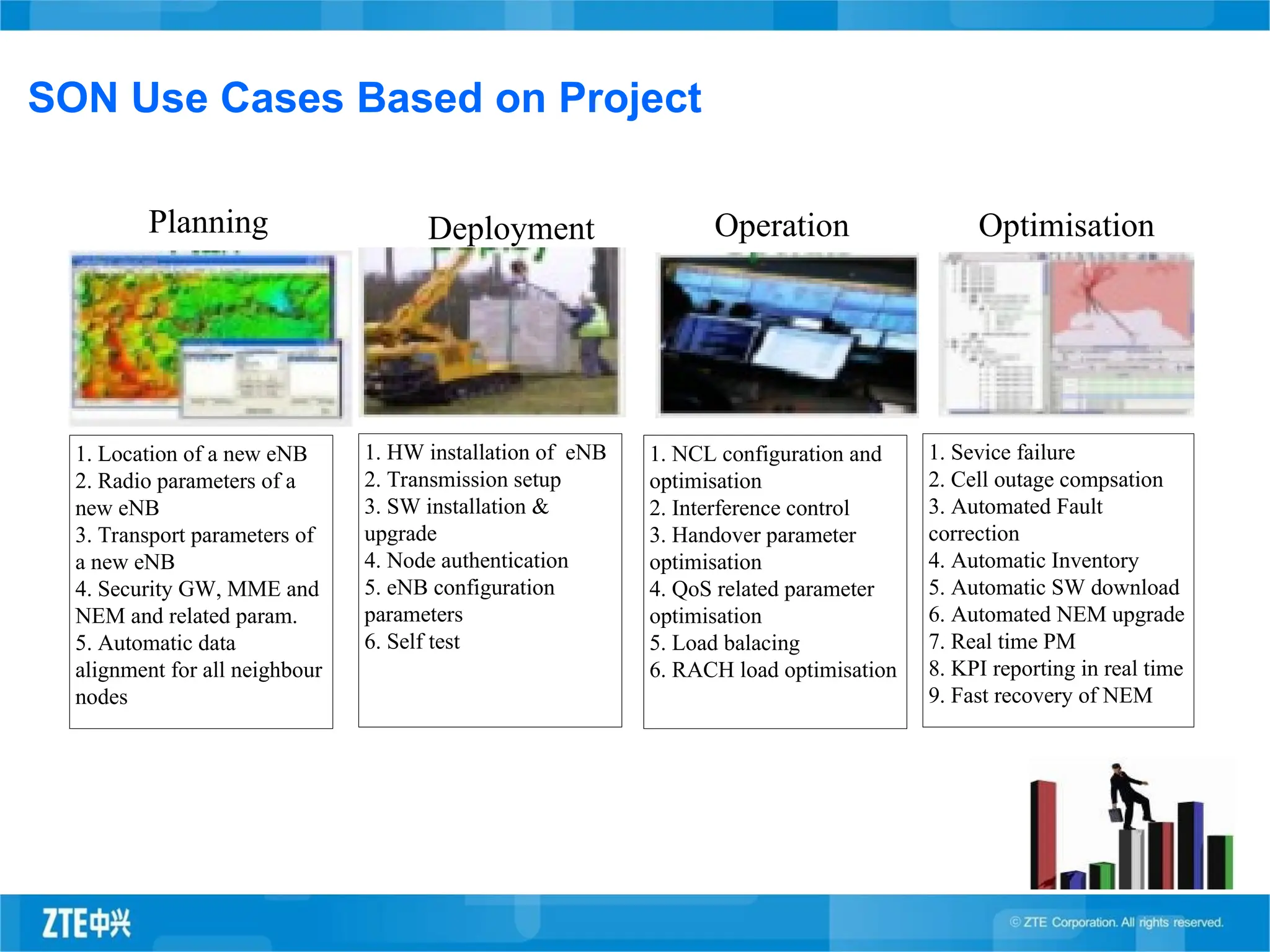
SON Use CasesBased on Project
Planning Deployment Operation Optimisation
1. Location of a new eNB
2. Radio parameters of a
new eNB
3. Transport parameters of
a new eNB
4. Security GW, MME and
NEM and related param.
5. Automatic data
alignment for all neighbour
nodes
1. HW installation of eNB
2. Transmission setup
3. SW installation &
upgrade
4. Node authentication
5. eNB configuration
parameters
6. Self test
1. NCL configuration and
optimisation
2. Interference control
3. Handover parameter
optimisation
4. QoS related parameter
optimisation
5. Load balacing
6. RACH load optimisation
1. Sevice failure
2. Cell outage compsation
3. Automated Fault
correction
4. Automatic Inventory
5. Automatic SW download
6. Automated NEM upgrade
7. Real time PM
8. KPI reporting in real time
9. Fast recovery of NEM
38.
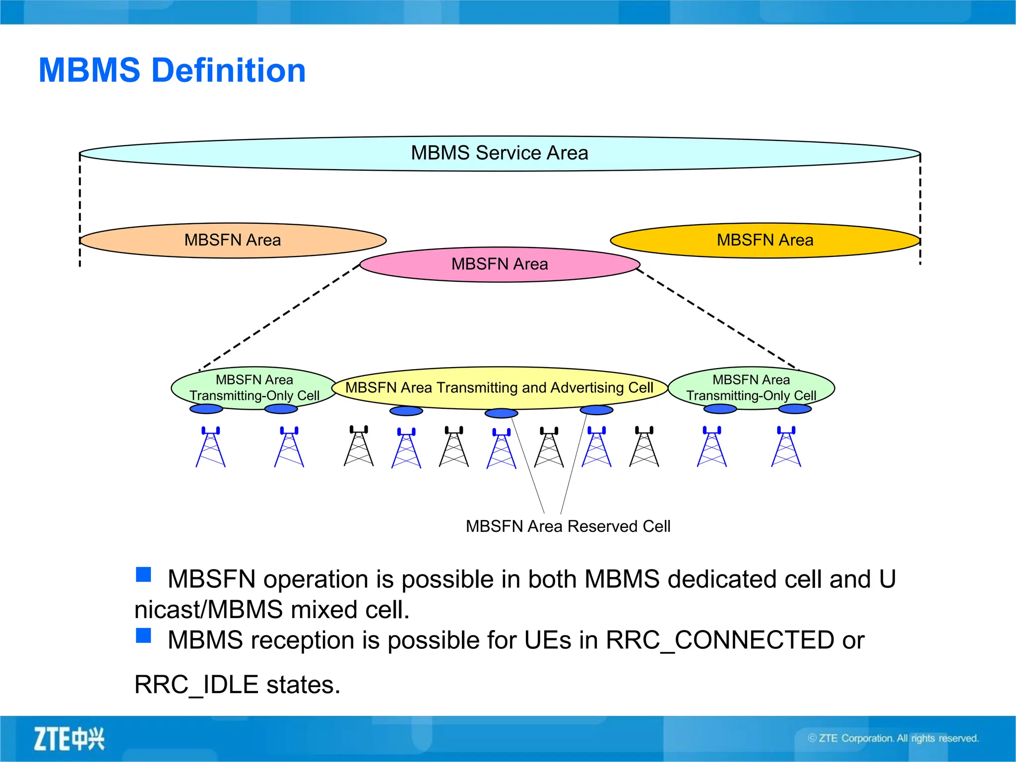
MBMS Definition
MBSFN Area
Transmitting-OnlyCell
MBMS Service Area
MBSFN Area
MBSFN Area
MBSFN Area
MBSFN Area Transmitting and Advertising Cell
MBSFN Area
Transmitting-Only Cell
MBSFN Area Reserved Cell
MBSFN operation is possible in both MBMS dedicated cell and U
nicast/MBMS mixed cell.
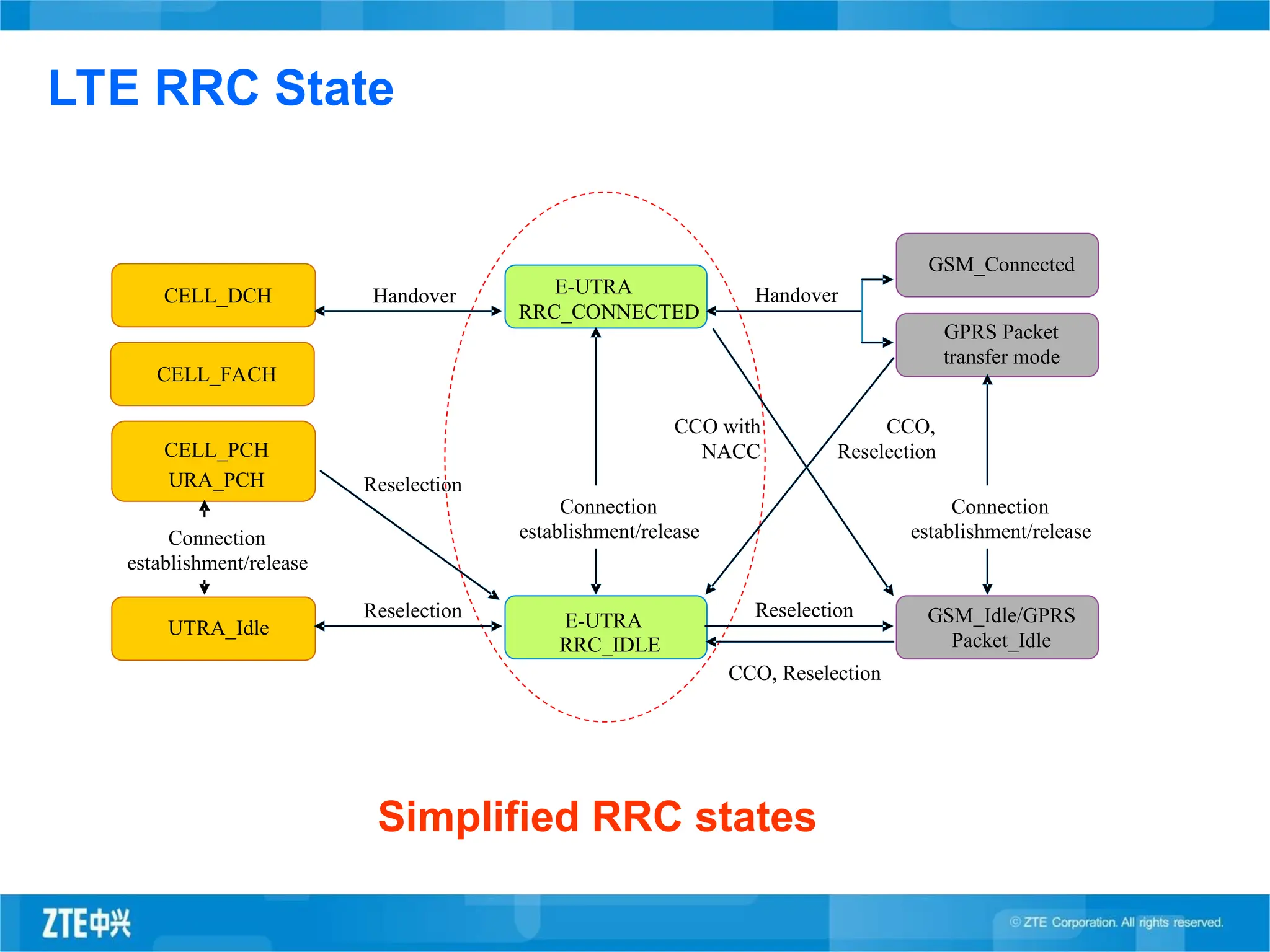
MBMS reception is possible for UEs in RRC_CONNECTED or
RRC_IDLE states.
39.
Mobile TechnologyOverview
LTE Features & Performance
ZTE LTE Network Solution
40.
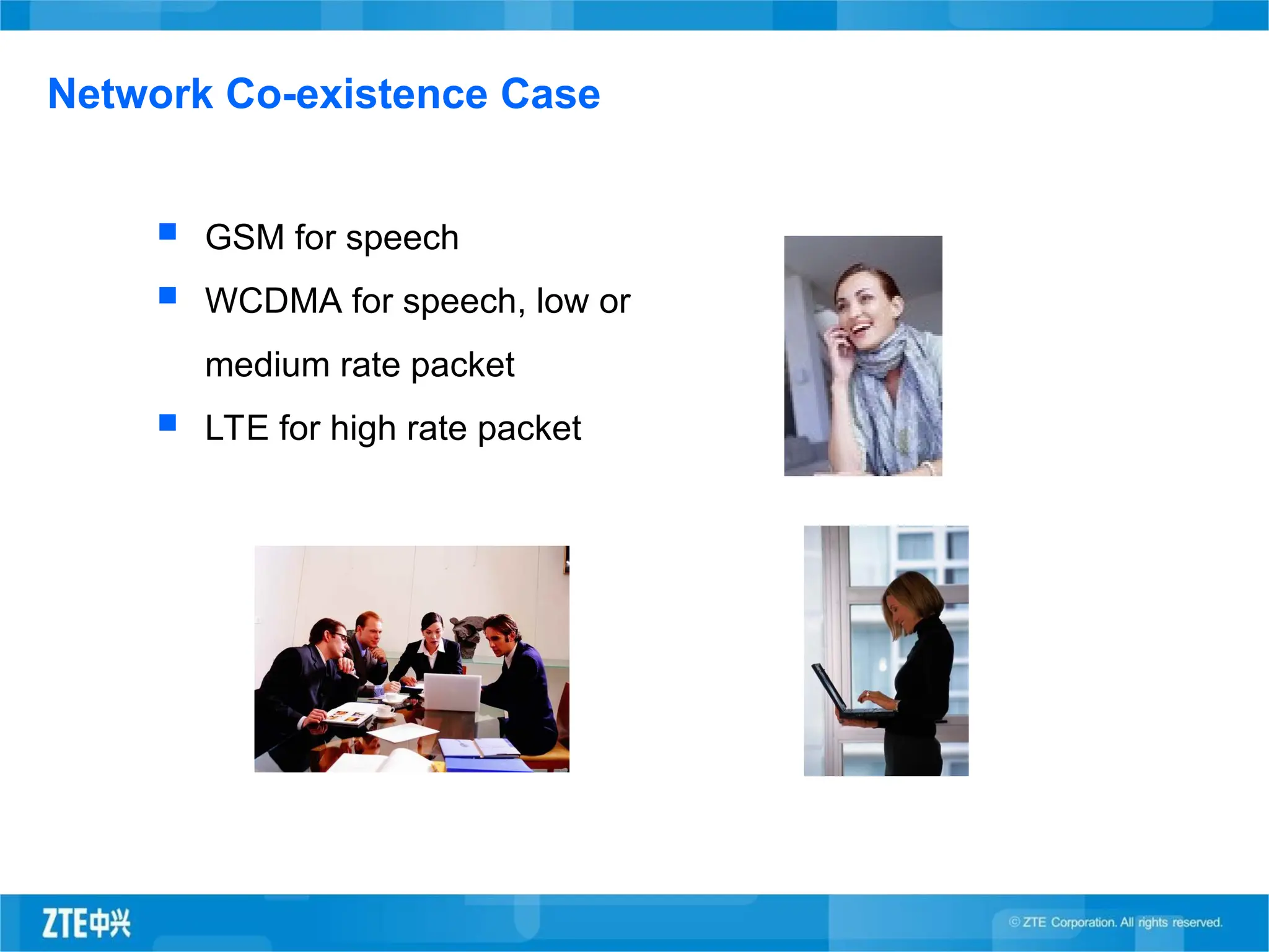
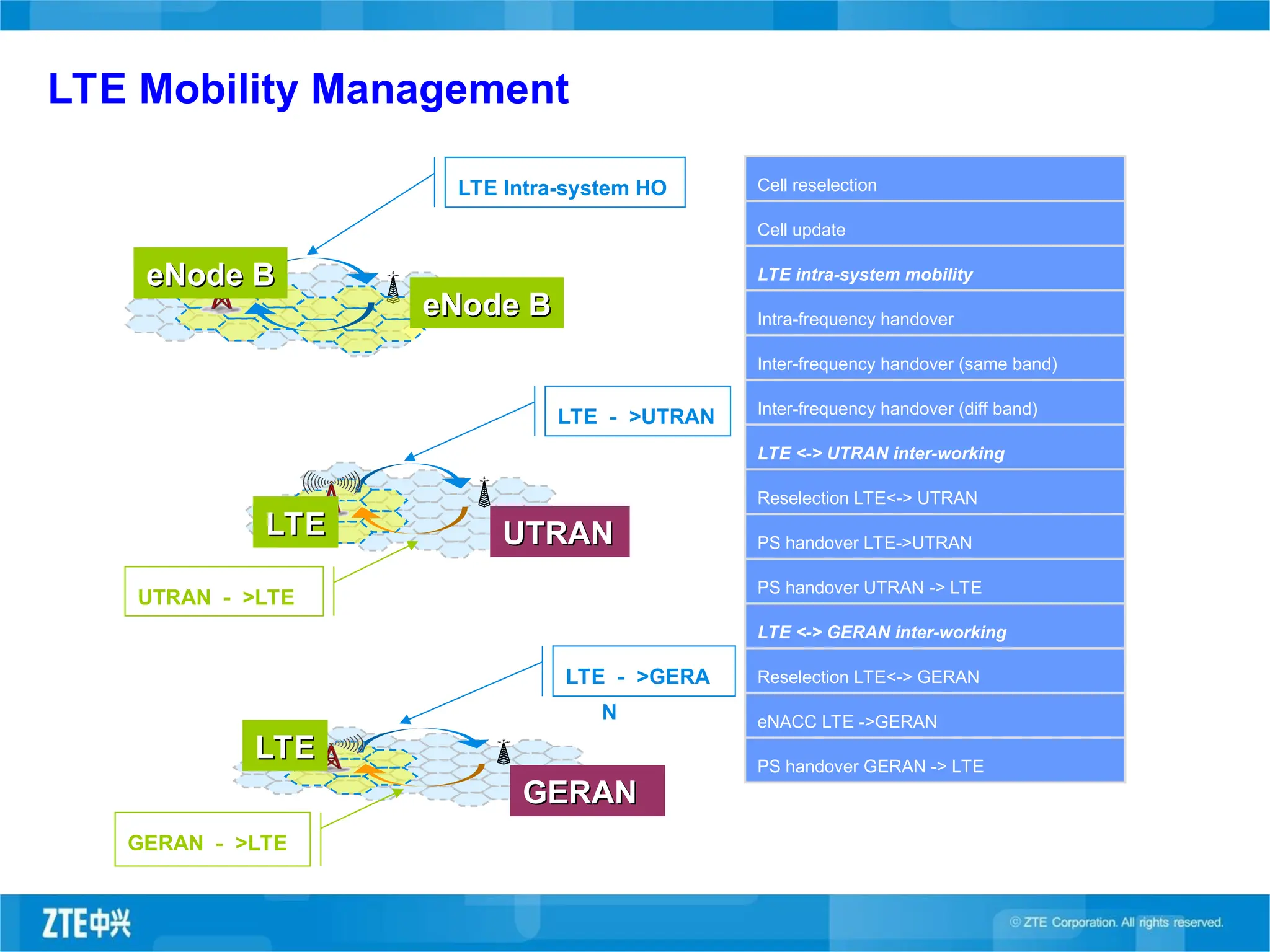
GSM forspeech
WCDMA for speech, low or
medium rate packet
LTE for high rate packet
Network Co-existence Case
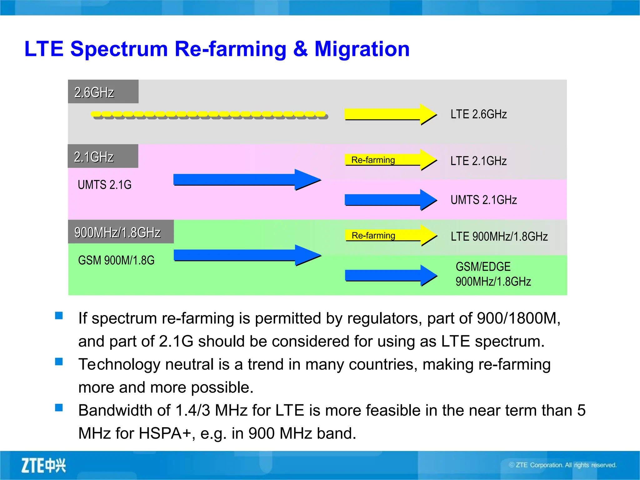
LTE Spectrum Re-farming& Migration
LTE 2.6GHz
UMTS 2.1G
2.1GHz
2.1GHz
2.6GHz
2.6GHz
Re-farming LTE 2.1GHz
UMTS 2.1GHz
If spectrum re-farming is permitted by regulators, part of 900/1800M,
and part of 2.1G should be considered for using as LTE spectrum.
Technology neutral is a trend in many countries, making re-farming
more and more possible.
Bandwidth of 1.4/3 MHz for LTE is more feasible in the near term than 5
MHz for HSPA+, e.g. in 900 MHz band.
GSM 900M/1.8G
900MHz/1.8GHz
900MHz/1.8GHz Re-farming LTE 900MHz/1.8GHz
GSM/EDGE
900MHz/1.8GHz
43.
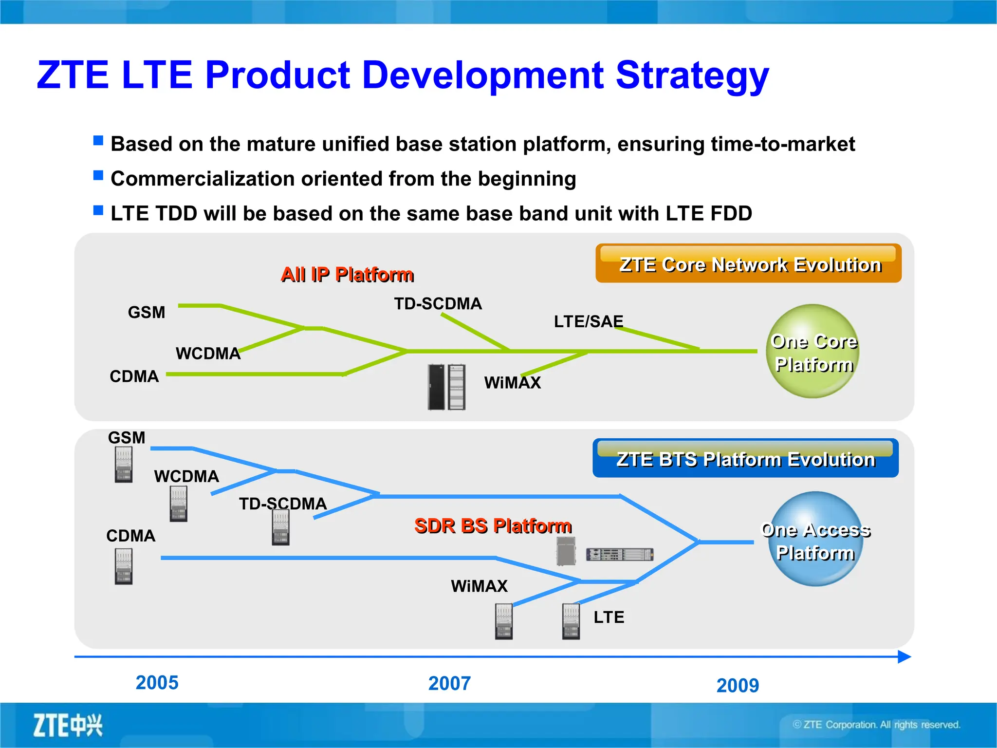
ZTE LTE ProductDevelopment Strategy
2005 2007
SDR BS Platform
2009
GSM
WCDMA
TD-SCDMA
CDMA
WiMAX
GSM
WCDMA
CDMA
TD-SCDMA
All IP Platform
WiMAX
LTE/SAE
LTE
Based on the mature unified base station platform, ensuring time-to-market
Commercialization oriented from the beginning
LTE TDD will be based on the same base band unit with LTE FDD
ZTE BTS Platform Evolution
One Access
Platform
ZTE Core Network Evolution
One Core
Platform
44.
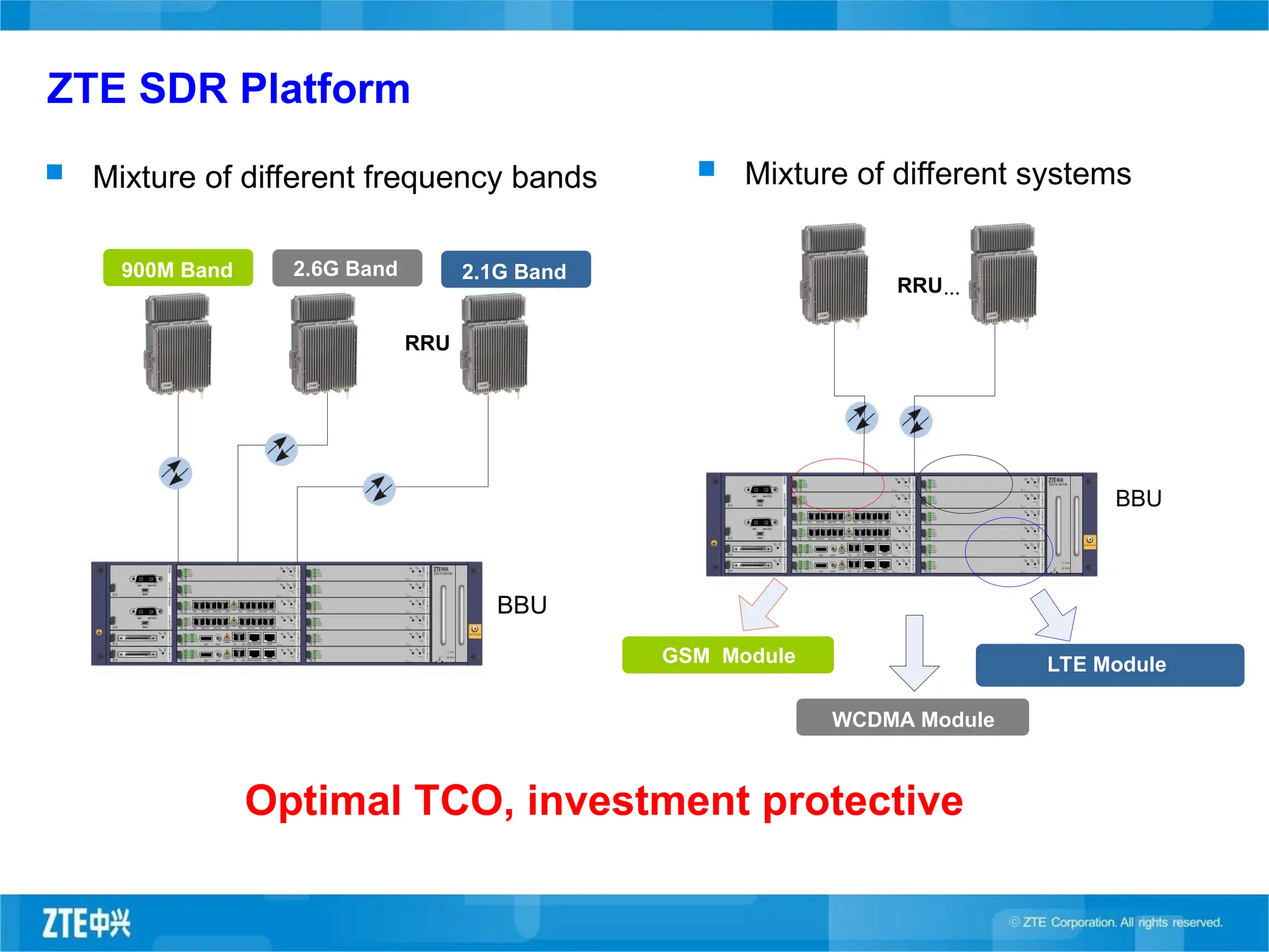
ZTE SDR Platform
Mixture of different frequency bands Mixture of different systems
Optimal TCO, investment protective
Cellular band AWS band 700M band
BBU
RRU
900M Band 2.6G Band 2.1G Band
GSM Module
WCDMA Module
UMB Service Module
BBU
RRU...
LTE Module
45.
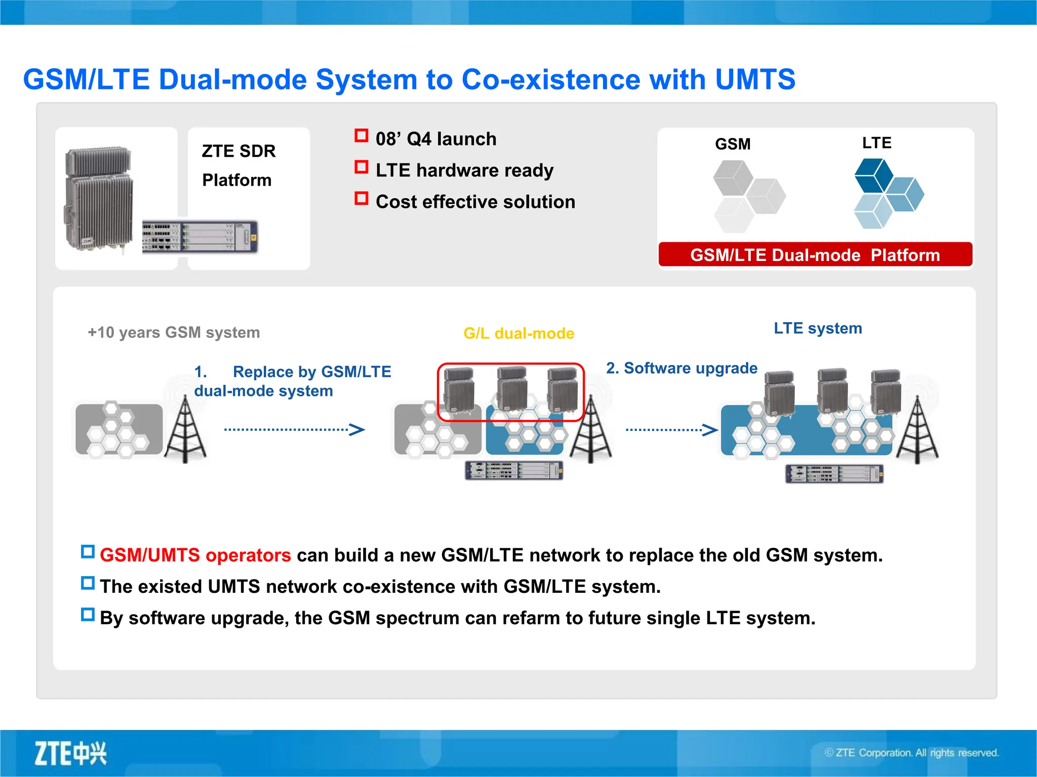
2. Software upgrade
LTEsystem
+10 years GSM system
GSM/UMTS operators can build a new GSM/LTE network to replace the old GSM system.
The existed UMTS network co-existence with GSM/LTE system.
By software upgrade, the GSM spectrum can refarm to future single LTE system.
1. Replace by GSM/LTE
dual-mode system
08’ Q4 launch
LTE hardware ready
Cost effective solution
GSM LTE
GSM/LTE Dual-mode Platform
GSM/LTE Dual-mode System to Co-existence with UMTS
G/L dual-mode
ZTE SDR
Platform
46.
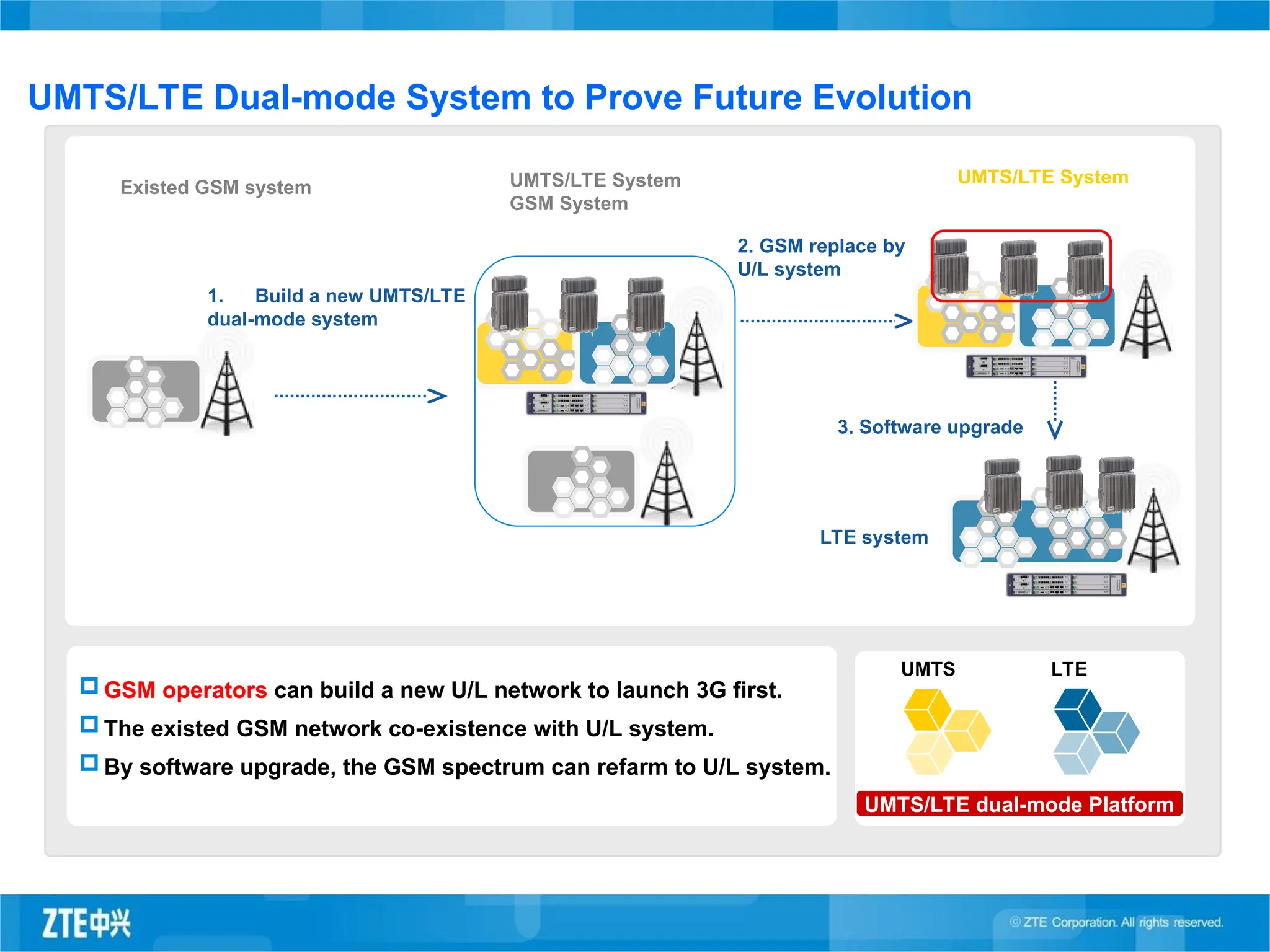
UMTS/LTE System
GSM System
1.Build a new UMTS/LTE
dual-mode system
Existed GSM system
2. GSM replace by
U/L system
UMTS/LTE System
LTE system
3. Software upgrade
GSM operators can build a new U/L network to launch 3G first.
The existed GSM network co-existence with U/L system.
By software upgrade, the GSM spectrum can refarm to U/L system.
UMTS/LTE Dual-mode System to Prove Future Evolution
UMTS LTE
UMTS/LTE dual-mode Platform
47.
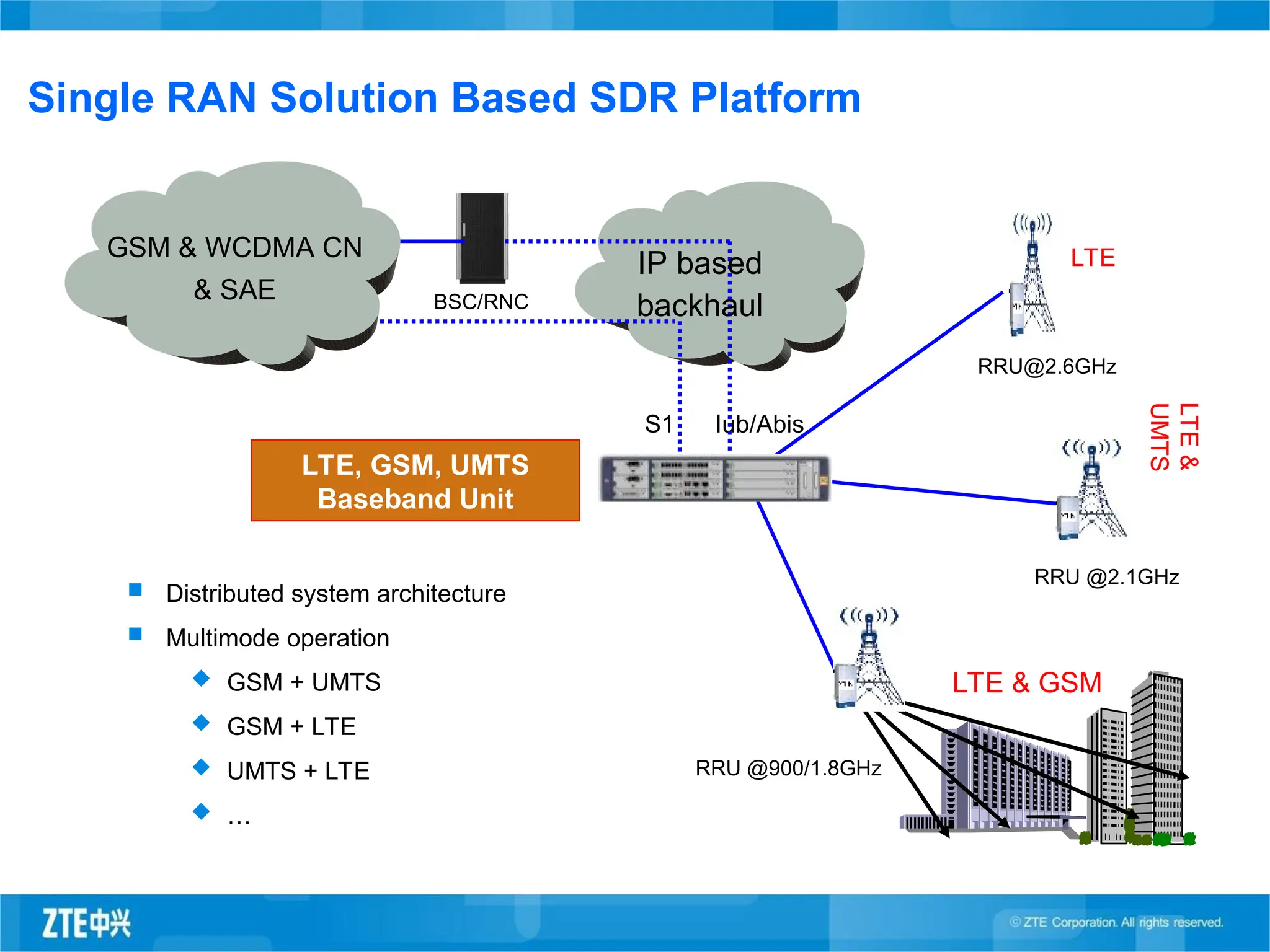
Single RAN SolutionBased SDR Platform
Iub/Abis
RRU @900/1.8GHz
LTE, GSM, UMTS
Baseband Unit
RRU @2.1GHz
BSC/RNC
RRU@2.6GHz
S1
IP based
backhaul
GSM & WCDMA CN
& SAE
LTE
LTE
&
UMTS
LTE & GSM
Distributed system architecture
Multimode operation
GSM + UMTS
GSM + LTE
UMTS + LTE
…
48.
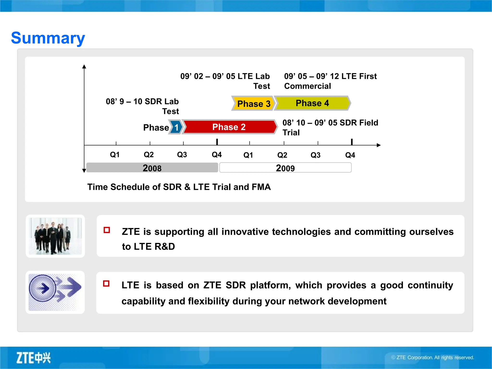
Summary
Time Schedule ofSDR & LTE Trial and FMA
Phase 1 Phase 2
Phase 3 Phase 4
Q1 Q3
Q2 Q4 Q1 Q3
Q2 Q4
08’ 10 – 09’ 05 SDR Field
Trial
09’ 05 – 09’ 12 LTE First
Commercial
08’ 9 – 10 SDR Lab
Test
09’ 02 – 09’ 05 LTE Lab
Test
2008 2009
ZTE is supporting all innovative technologies and committing ourselves
to LTE R&D
LTE is based on ZTE SDR platform, which provides a good continuity
capability and flexibility during your network development
Editor's Notes
#5 Remarks:
1.VF/TIM/Telenor/Telefonica will adopt WCDMA evolution to LTE FDD;
2.CMCC chose TD-SCDMA evolution to LTE TDD;
3.Telstra gave up CDMA 2000 EVDO and choose WCDMA evolution to LTE FDD;
4.Verizon chose EVDO Rev A evolution to LTE FDD;
5.Almost all the top 10 operators will choose LTE evolution.
#6 Remarks:
LTE has many advantages such as highest data rate, highest spectrum efficiency, various spectrum bands choice, etc;
The UMB industry becomes very weak and even Qualcomm decided to give up continuous UMB R&D.
#8
Issues with Migrating from Legacy RAN architecture to Flat RAN Architecture with HSPA+ eNodeBs
HSPA+: 3GPP release 7
HSPA+: 3GPP Flat Architecture 64 QAM and 2*2 MIMO in release 8
ZTEs Recommendations: ZTE proposes that Flat Architecture with HSPA+ is not easy to realize. ZTE propose to move to LTE.
Continue with HSPA+ using release 7 with Legacy Architecture
One reason to go Flat with HSPA+ will be for PS domain but a hybrid network architecture increases the complexitiy of managing the network
MIMO is not recommended with HSPA+ because it will require a change in NodeBs and existing handsets will not support the MIMO feature