Downloaded 87 times
![Page45
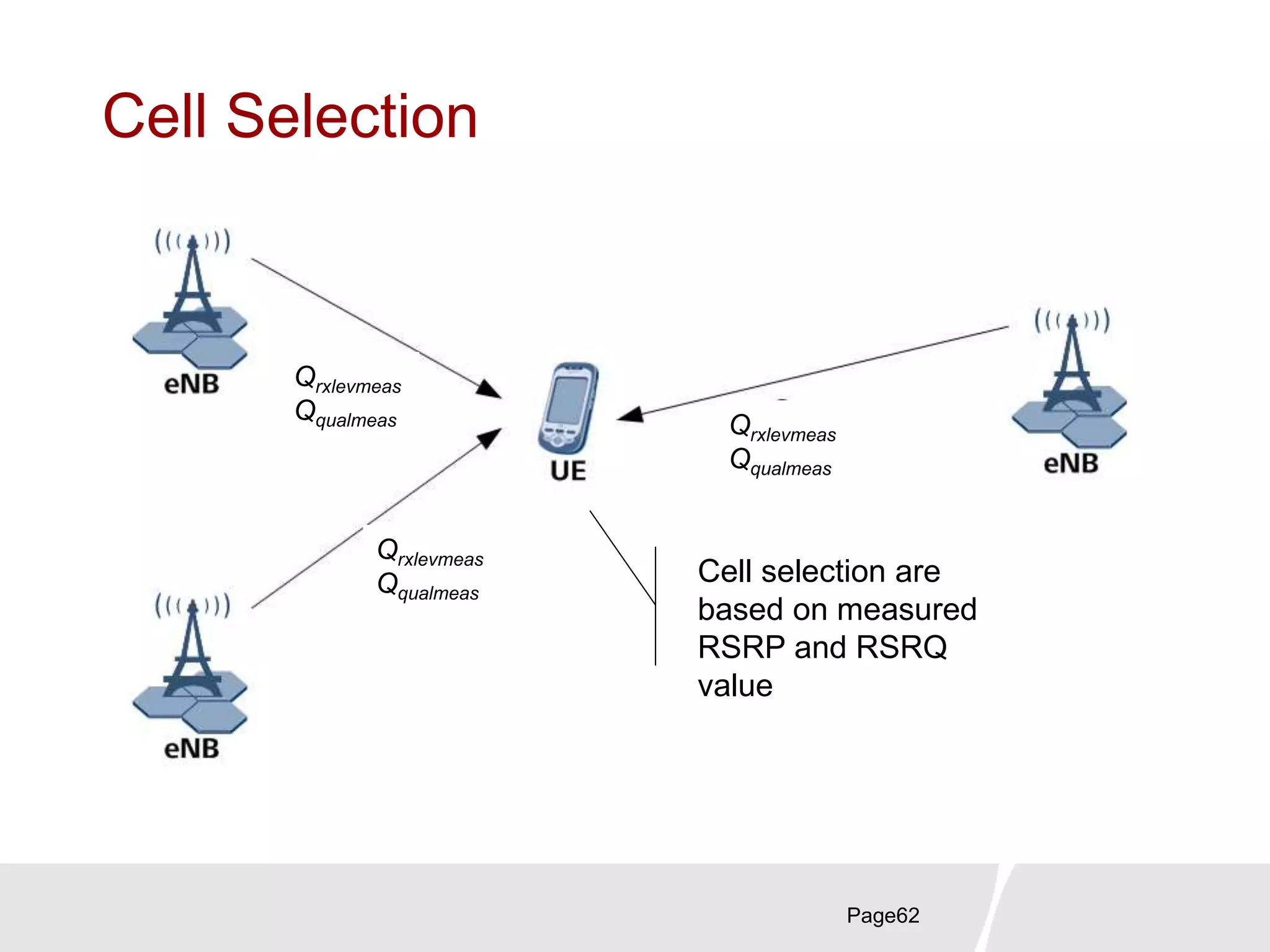
Channel BW and RB
Channel bandwidth BWChannel [MHz] 1.4 3 5 10 15 20
Transmission bandwidth
configuration NRB
6 15 25 50 75 100
Transmission
Bandwidth [RB]
Transmission Bandwidth Configuration [RB]
Channel Bandwidth [MHz]
Resourceblock
Channeledge
Channeledge
DC carrier (downlink only)Active Resource Blocks
For details, please refer to protocol 36.101](https://image.slidesharecdn.com/lteprinciplesoverview-190829135409/75/Lte-principles-overview-45-2048.jpg)
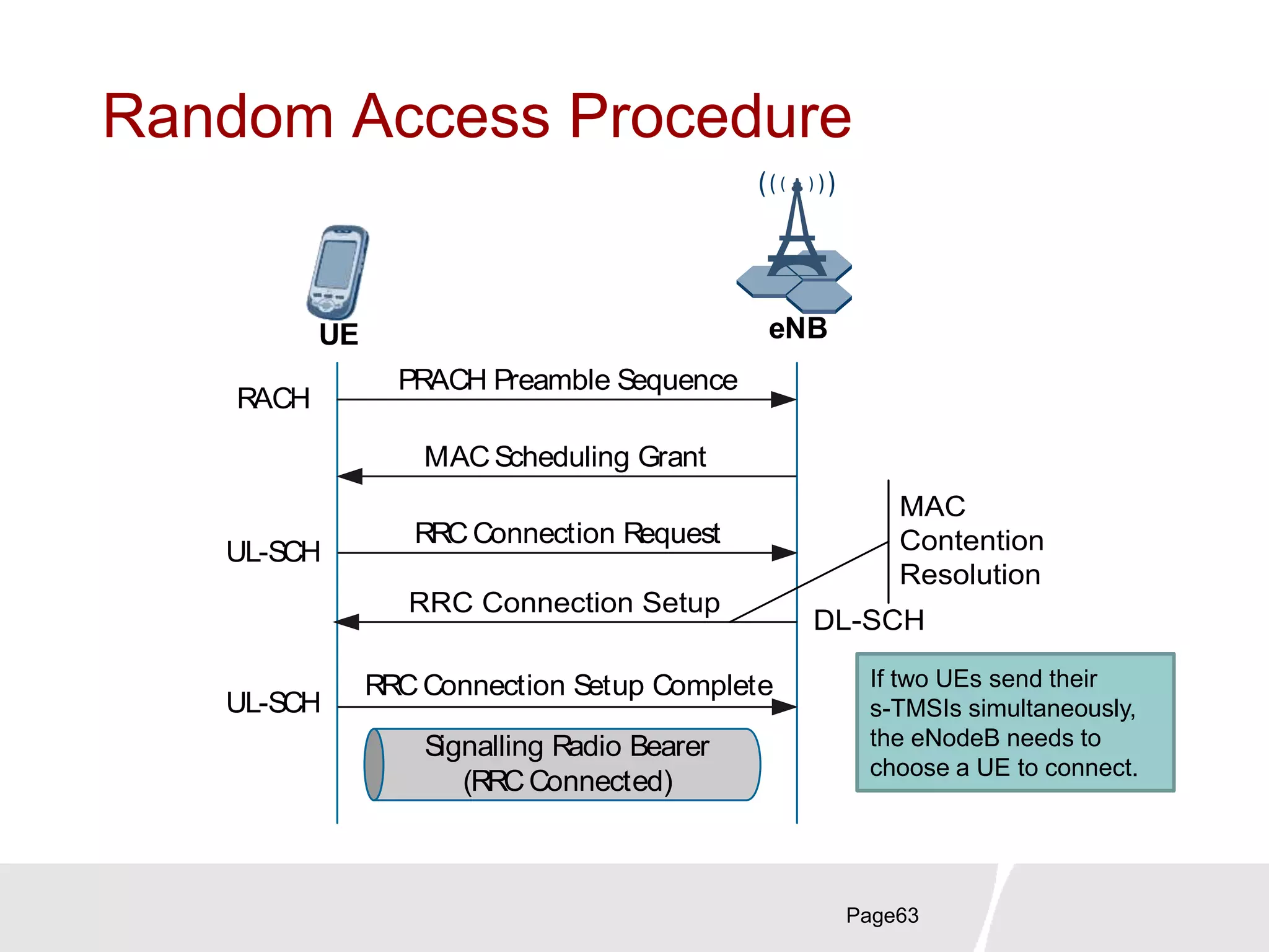
![LTE-A Key Technogies
Page88
Carrier
Aggregation
HetNet
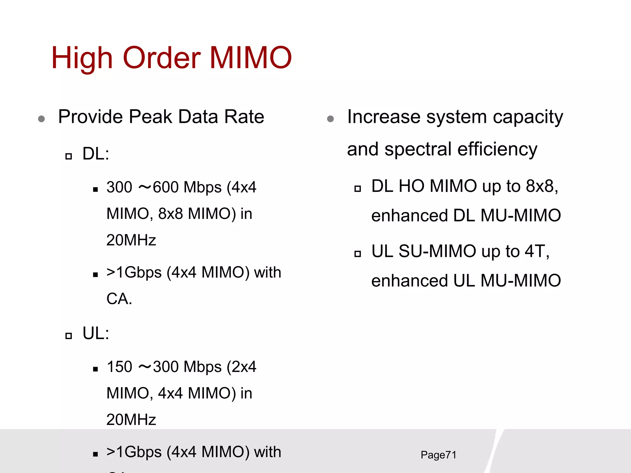
High Order
MIMO
[06-
2012]
Av. DL
3.7bps/Hz
Av. UL
2.0bps/Hz
Coordinate
d Multi-
Point
1. To boost LTE radio capacity
and spectrum efficiency
2. To fulfill ITU-R “IMT-
Advanced” recommendation](https://image.slidesharecdn.com/lteprinciplesoverview-190829135409/75/Lte-principles-overview-87-2048.jpg)


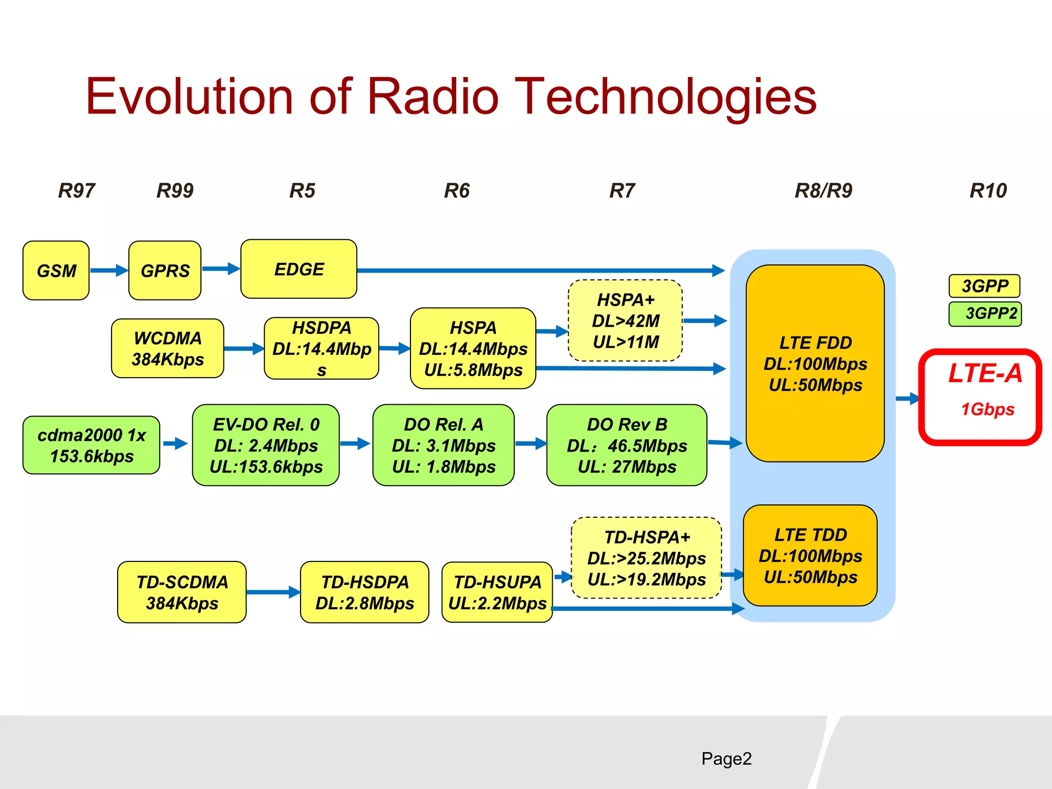
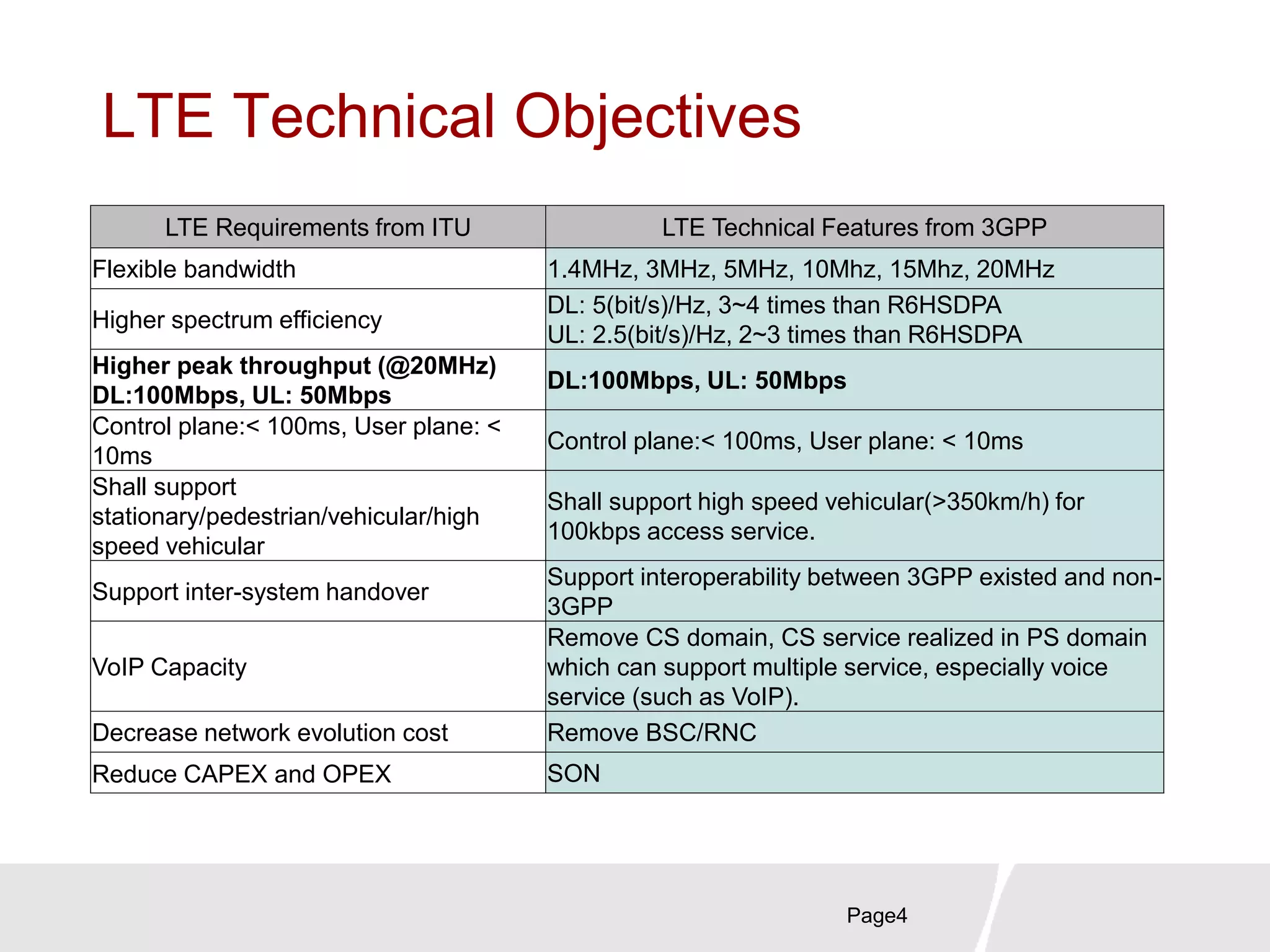
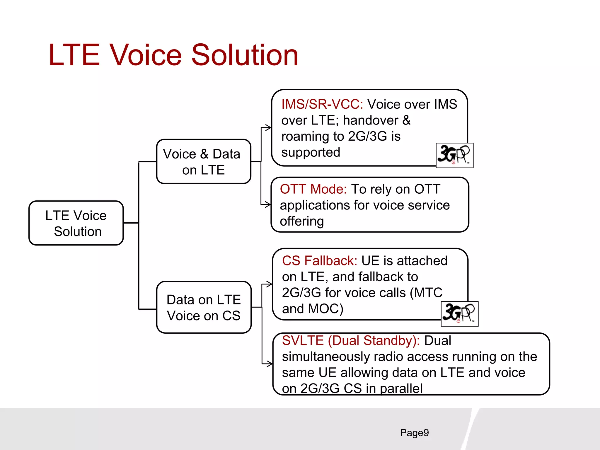
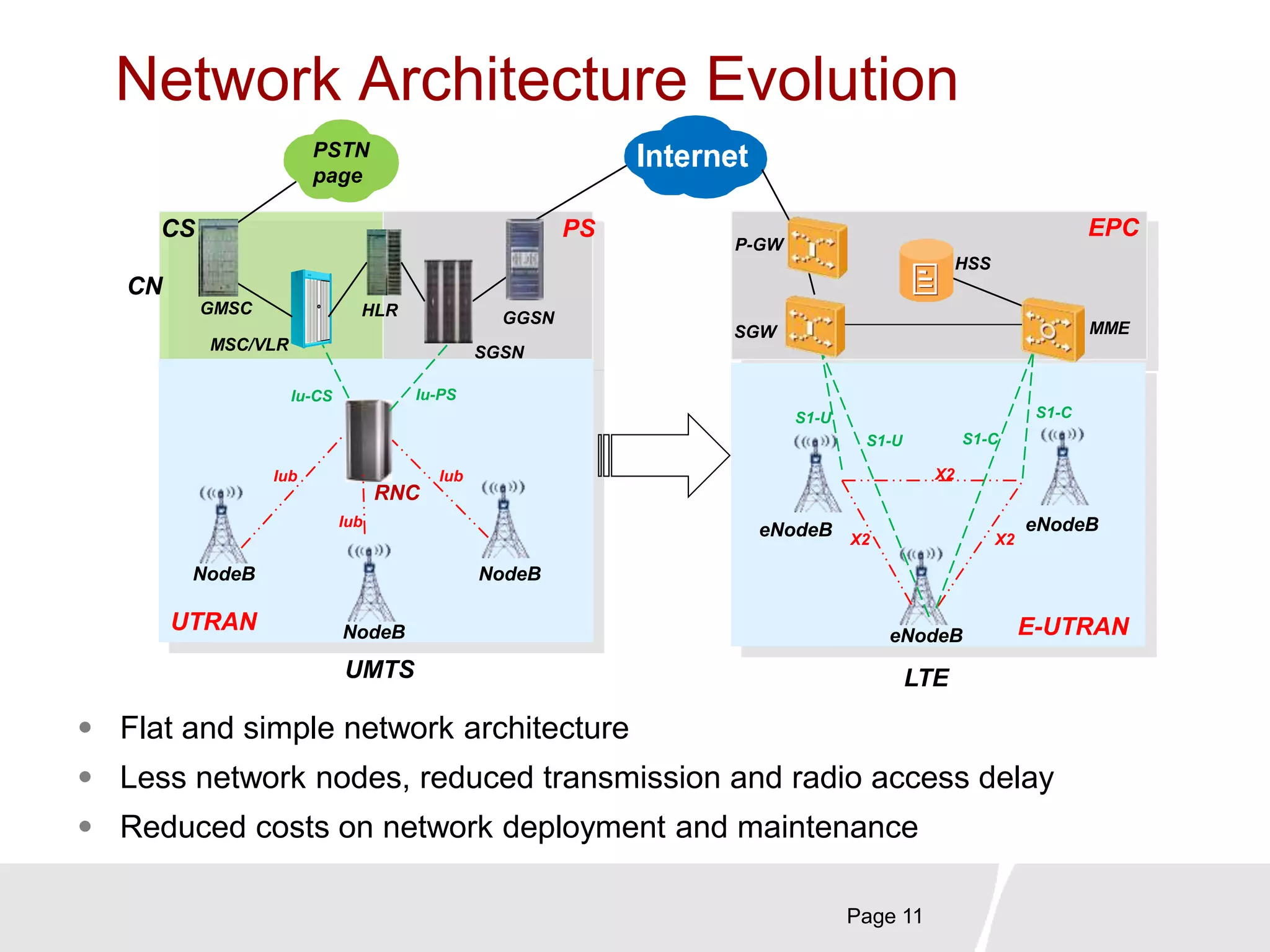
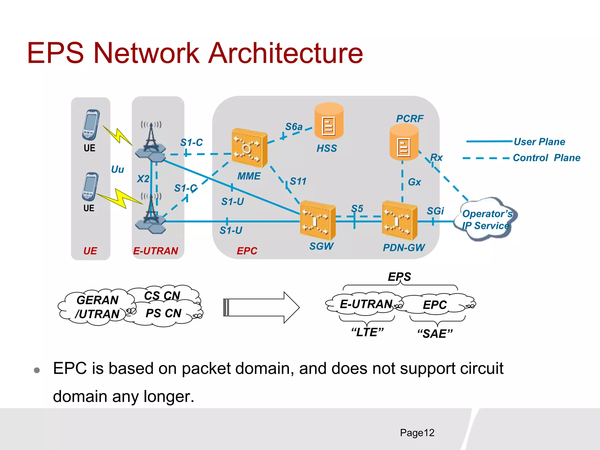
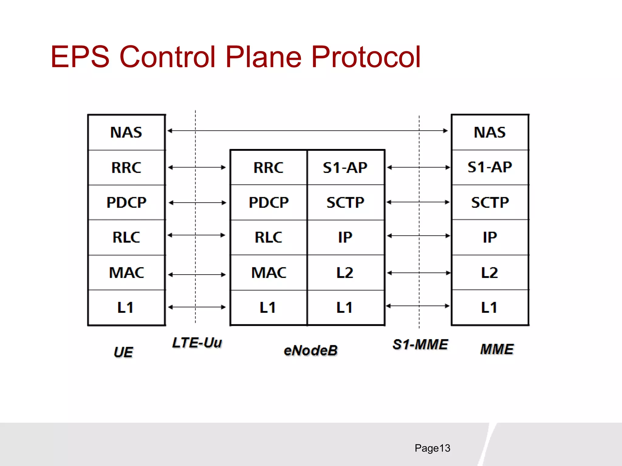
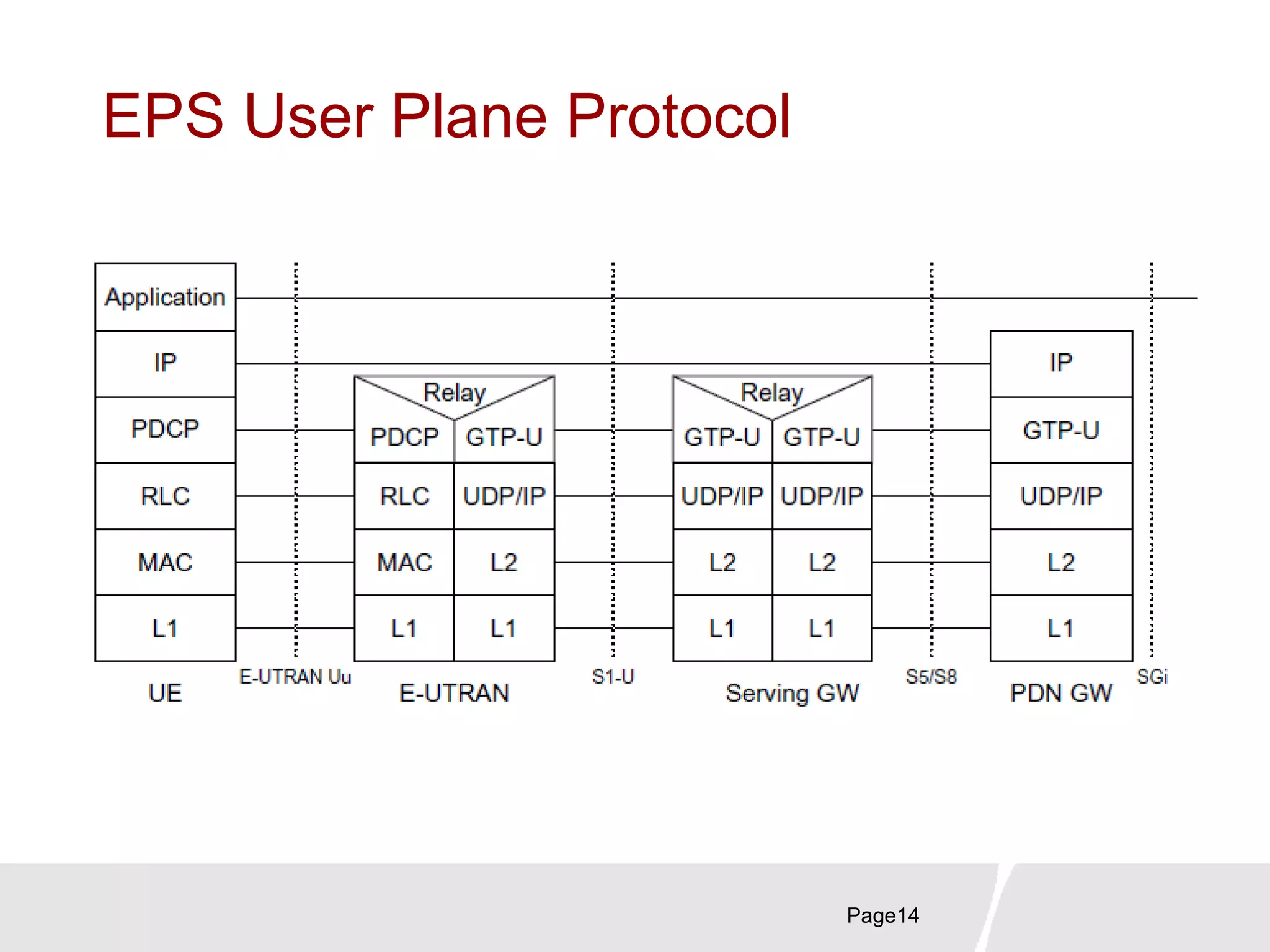
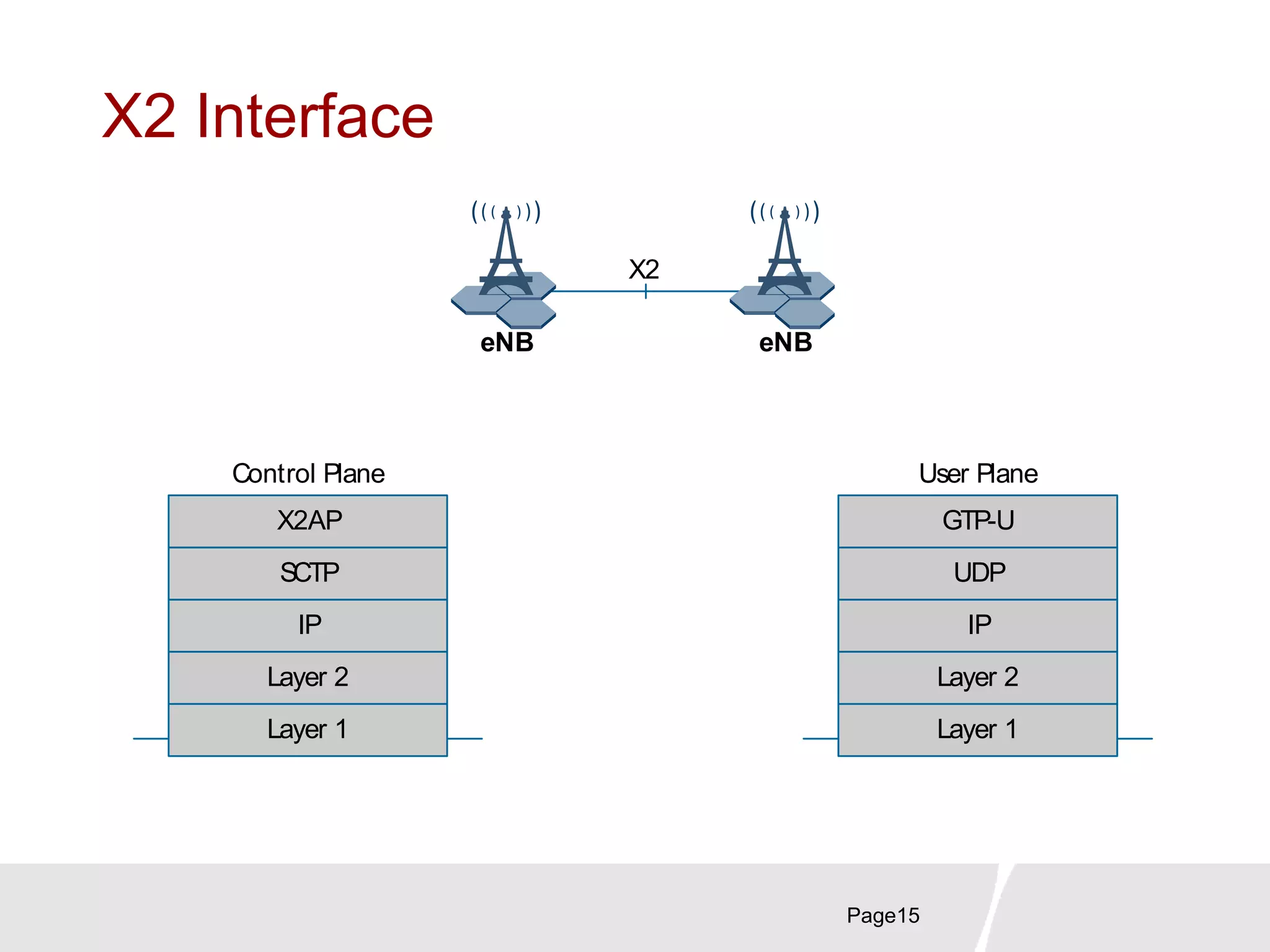
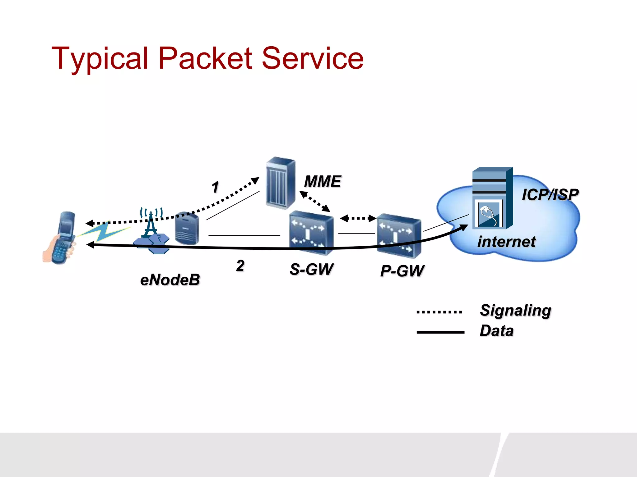
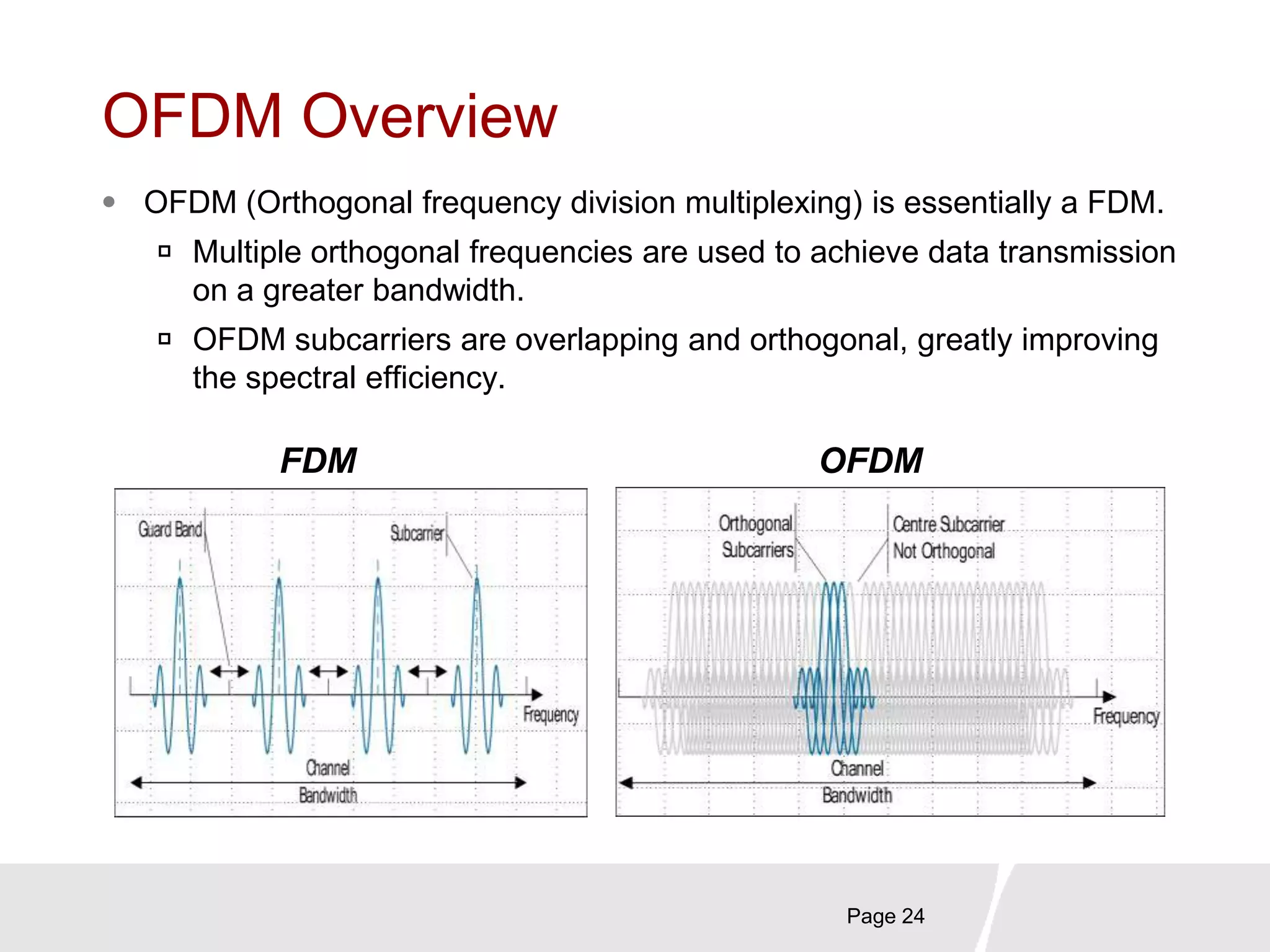
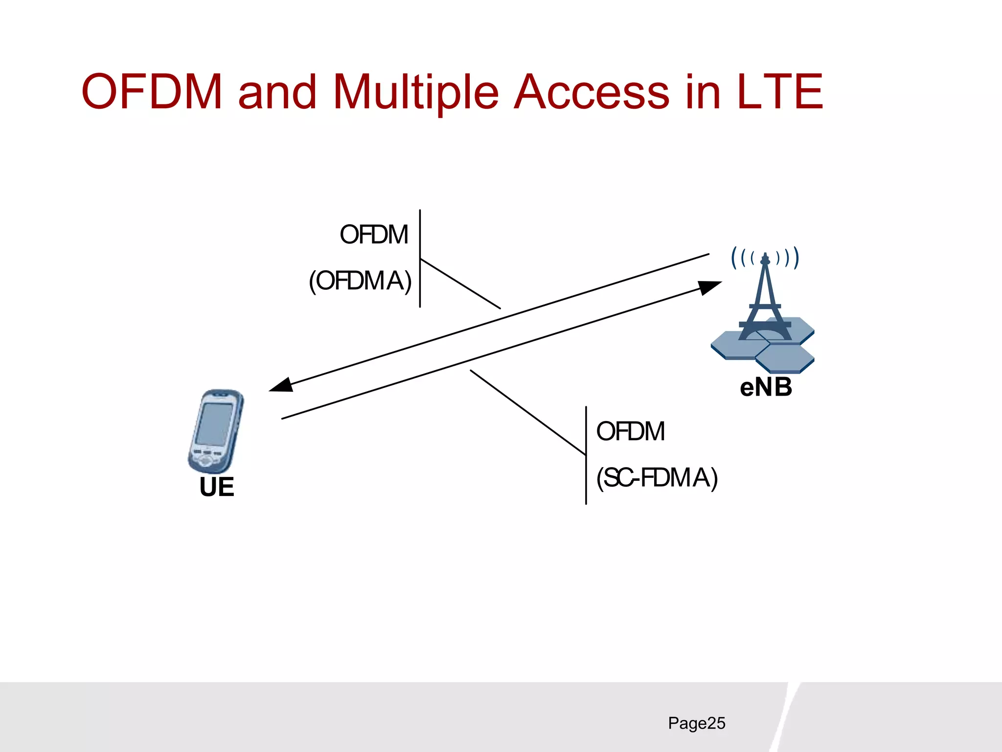
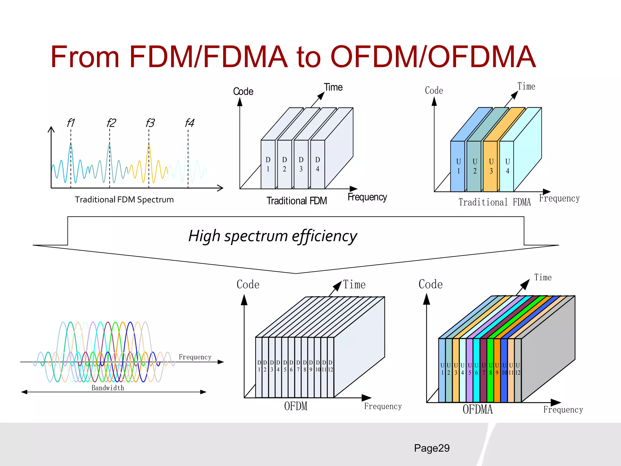
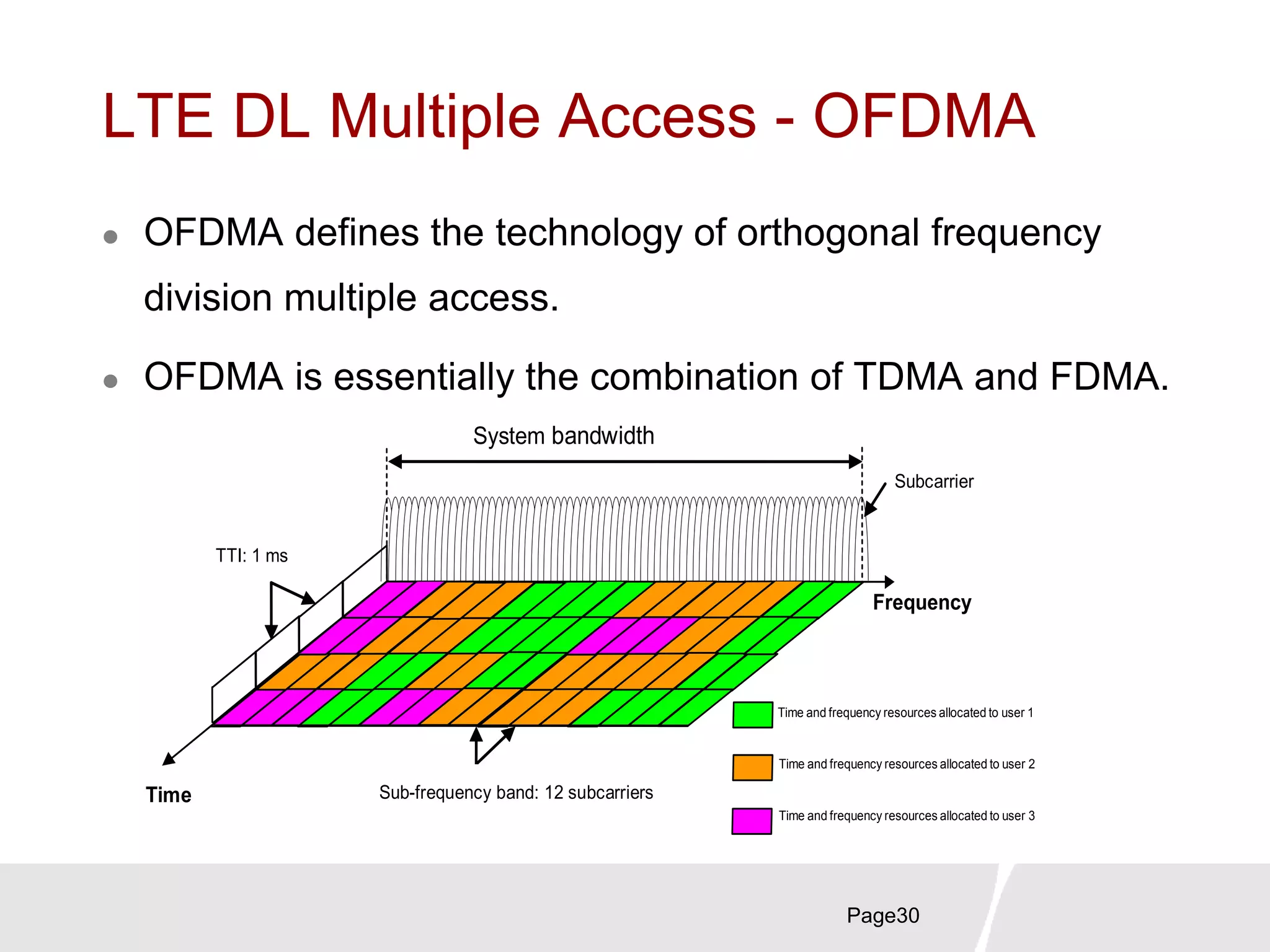
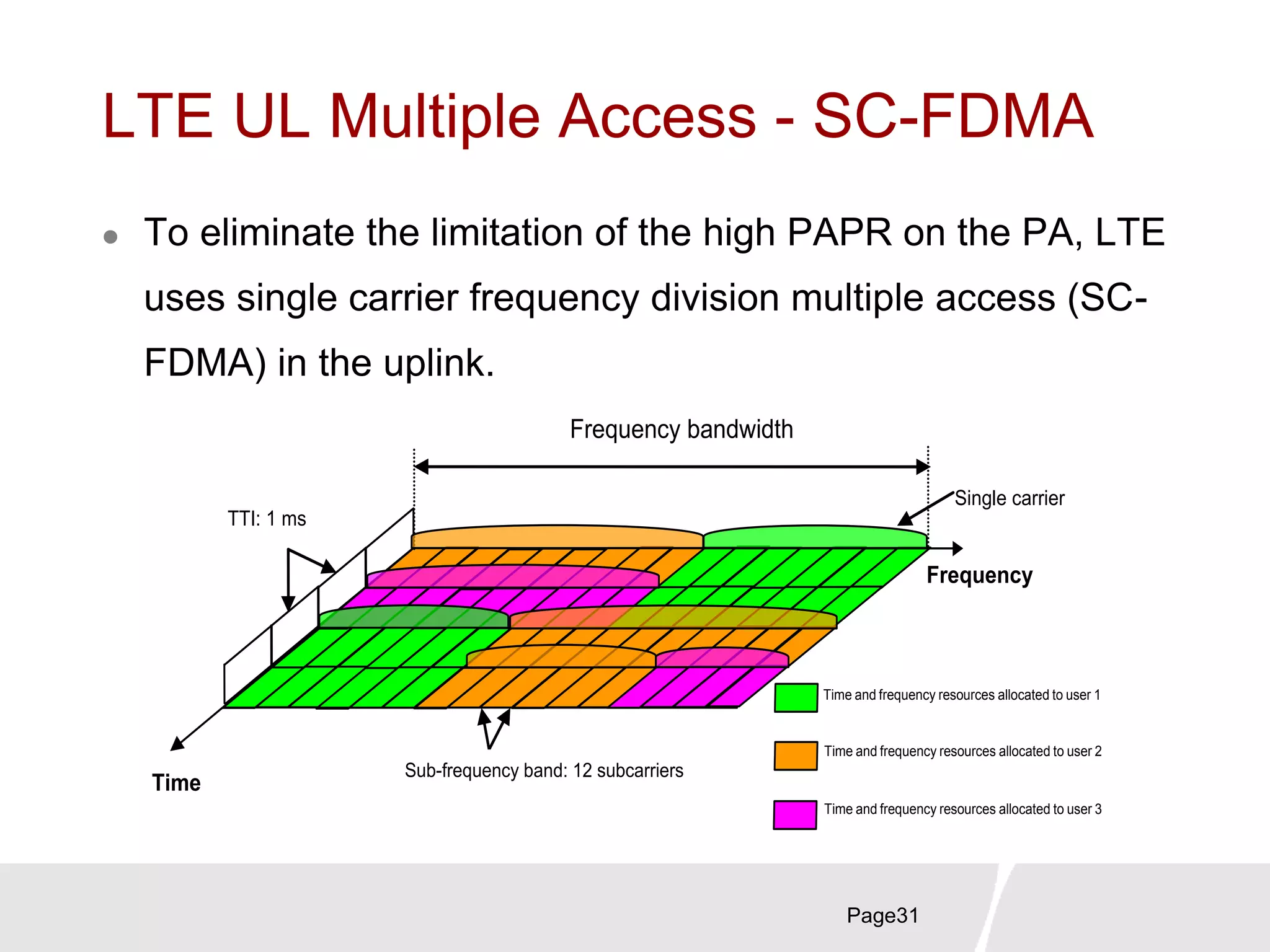
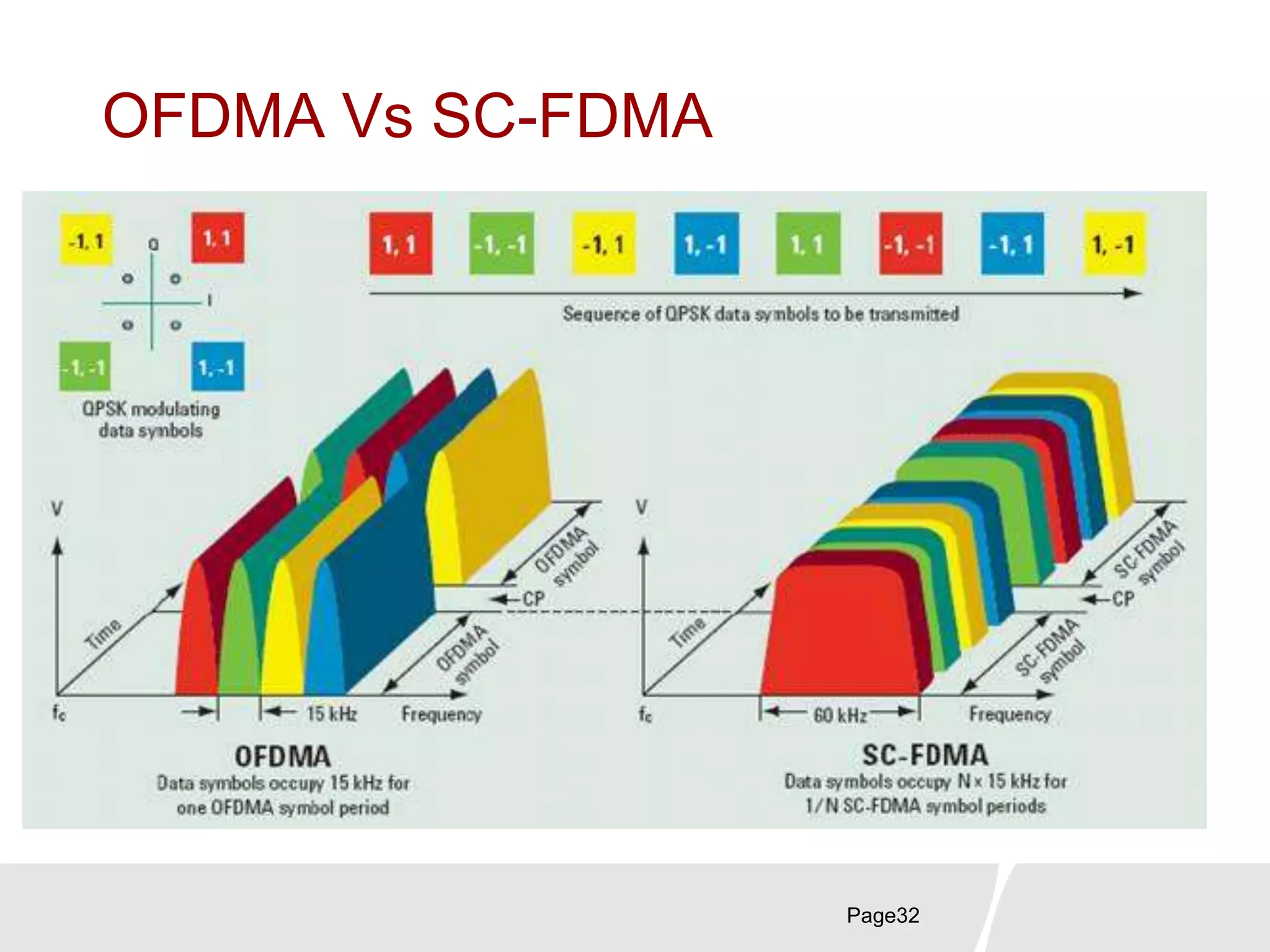
This document provides an overview of LTE technology from Huawei, including: 1. It describes the evolution of radio technologies leading up to LTE, which can achieve downlink speeds of 100Mbps and uplink speeds of 50Mbps. 2. It explains the LTE network architecture, which uses a flat, simplified design compared to previous standards. Key elements include the E-UTRAN, EPC, and interfaces like S1 and X2. 3. It introduces LTE air interface principles like OFDMA for downlink multiple access and SC-FDMA for uplink multiple access, allowing high spectrum efficiency through orthogonal frequency division.


