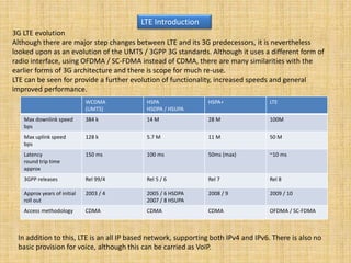
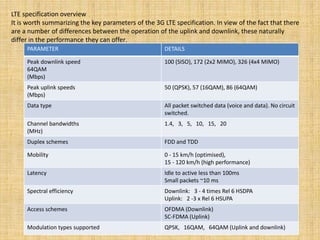
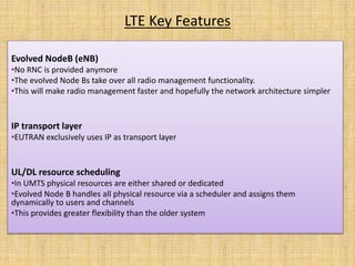
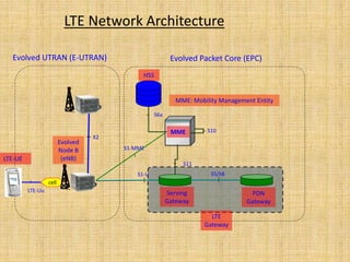
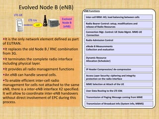
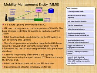
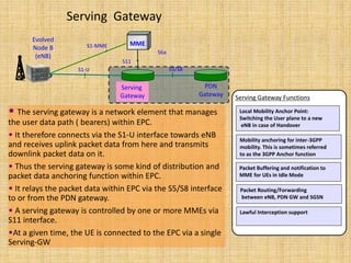
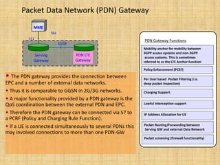
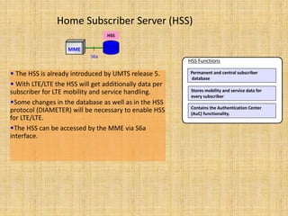
The document discusses the evolution of 3G networks to LTE networks. It describes key technologies such as OFDMA, SC-FDMA, and MIMO that improve spectral efficiency and throughput. The LTE network architecture is presented, including elements such as the E-UTRAN, MME, serving gateway, PDN gateway, and HSS. The interfaces between these elements are also outlined.
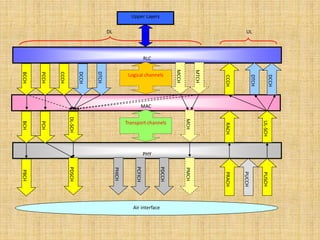
2. 3G LTE evolution
Although there are major step changes between LTE and its 3G predecessors, it is nevertheless
looked upon as an evolution of the UMTS / 3GPP 3G standards. Although it uses a different form of
radio interface, using OFDMA / SC-FDMA instead of CDMA, there are many similarities with the
earlier forms of 3G architecture and there is scope for much re-use.
LTE can be seen for provide a further evolution of functionality, increased speeds and general
improved performance.
LTE Introduction
WCDMA
(UMTS)
HSPA
HSDPA / HSUPA
HSPA+ LTE
Max downlink speed
bps
384 k 14 M 28 M 100M
Max uplink speed
bps
128 k 5.7 M 11 M 50 M
Latency
round trip time
approx
150 ms 100 ms 50ms (max) ~10 ms
3GPP releases Rel 99/4 Rel 5 / 6 Rel 7 Rel 8
Approx years of initial
roll out
2003 / 4 2005 / 6 HSDPA
2007 / 8 HSUPA
2008 / 9 2009 / 10
Access methodology CDMA CDMA CDMA OFDMA / SC-FDMA
In addition to this, LTE is an all IP based network, supporting both IPv4 and IPv6. There is also no
basic provision for voice, although this can be carried as VoIP.
3. 3GPP LTE technologies
LTE has introduced a number of new technologies when compared to the previous cellular
systems. They enable LTE to be able to operate more efficiently with respect to the use of
spectrum, and also to provide the much higher data rates that are being required.
OFDM (Orthogonal Frequency Division Multiplex): OFDM technology has been
incorporated into LTE because it enables high data bandwidths to be transmitted efficiently
while still providing a high degree of resilience to reflections and interference. The access
schemes differ between the uplink and downlink: OFDMA (Orthogonal Frequency Division
Multiple Access is used in the downlink; while SC-FDMA(Single Carrier - Frequency Division
Multiple Access) is used in the uplink. SC-FDMA is used in view of the fact that its peak to
average power ratio is small and the more constant power enables high RF power amplifier
efficiency in the mobile handsets - an important factor for battery power equipment.
MIMO (Multiple Input Multiple Output): One of the main problems that previous
telecommunications systems has encountered is that of multiple signals arising from the
many reflections that are encountered. By using MIMO, these additional signal paths can be
used to advantage and are able to be used to increase the throughput.
4. When using MIMO, it is necessary to use multiple antennas to enable the different paths
to be distinguished. Accordingly schemes using 2 x 2, 4 x 2, or 4 x 4 antenna matrices can
be used. While it is relatively easy to add further antennas to a base station, the same is
not true of mobile handsets, where the dimensions of the user equipment limit the
number of antennas which should be place at least a half wavelength apart.
Architecture Evolution: With the very high data rate and low latency requirements for
3G LTE, it is necessary to evolve the system architecture to enable the improved
performance to be achieved. One change is that a number of the functions previously
handled by the core network have been transferred out to the periphery. Essentially this
provides a much "flatter" form of network architecture. In this way latency times can be
reduced and data can be routed more directly to its destination.
5. LTE specification overview
It is worth summarizing the key parameters of the 3G LTE specification. In view of the fact that there
are a number of differences between the operation of the uplink and downlink, these naturally
differ in the performance they can offer.
PARAMETER DETAILS
Peak downlink speed
64QAM
(Mbps)
100 (SISO), 172 (2x2 MIMO), 326 (4x4 MIMO)
Peak uplink speeds
(Mbps)
50 (QPSK), 57 (16QAM), 86 (64QAM)
Data type All packet switched data (voice and data). No circuit
switched.
Channel bandwidths
(MHz)
1.4, 3, 5, 10, 15, 20
Duplex schemes FDD and TDD
Mobility 0 - 15 km/h (optimised),
15 - 120 km/h (high performance)
Latency Idle to active less than 100ms
Small packets ~10 ms
Spectral efficiency Downlink: 3 - 4 times Rel 6 HSDPA
Uplink: 2 -3 x Rel 6 HSUPA
Access schemes OFDMA (Downlink)
SC-FDMA (Uplink)
Modulation types supported QPSK, 16QAM, 64QAM (Uplink and downlink)
6. LTE Key Features
Evolved NodeB (eNB)
•No RNC is provided anymore
•The evolved Node Bs take over all radio management functionality.
•This will make radio management faster and hopefully the network architecture simpler
IP transport layer
•EUTRAN exclusively uses IP as transport layer
UL/DL resource scheduling
•In UMTS physical resources are either shared or dedicated
•Evolved Node B handles all physical resource via a scheduler and assigns them
dynamically to users and channels
•This provides greater flexibility than the older system
8. Inter-cell RRM: HO, load balancing between cells
Radio Bearer Control: setup, modifications and
release of Radio Resources
Connection Mgt. Control: UE State Mgmt. MME-UE
Connection
Radio Admission Control
eNode B Measurements
Collection and evaluation
Dynamic Resource
Allocation (Scheduler)
eNB Functions
IP Header Compression/ de-compression
Access Layer Security: ciphering and integrity
protection on the radio interface
MME Selection at Attach of the UE
User Data Routing to the LTE GW.
Transmission of Paging Message coming from MME
Transmission of Broadcast Info (System info, MBMS)
Evolved
Node B
(eNB)cell
LTE-Uu
LTE-UE
•It is the only network element defined as part
of EUTRAN.
•It replaces the old Node B / RNC combination
from 3G.
•It terminates the complete radio interface
including physical layer.
•It provides all radio management functions
•An eNB can handle several cells.
•To enable efficient inter-cell radio
management for cells not attached to the same
eNB, there is a inter-eNB interface X2 specified.
It will allow to coordinate inter-eNB handovers
without direct involvement of EPC during this
process.
Evolved Node B (eNB)
9. Evolved
Node B
(eNB)
MME
Serving
Gateway
S1-U
S1-MME
S11
HSS
S6a
MME Functions
Non-Access-Stratum (NAS)
Signalling
Idle State Mobility Handling
Tracking Area updates
Security (Authentication,
Ciphering, Integrity protection)
Trigger and distribution of
Paging Messages to eNB
Roaming Control (S6a interface
to HSS)
Inter-CN Node Signaling
(S10 interface), allows efficient
inter-MME tracking area updates
and attaches
Signaling coordination for
LTE Bearer Setup/Release & HO
Subscriber attach/detach
Control plane NE in EPC
Mobility Management Entity (MME)
• It is a pure signaling entity inside the EPC.
• LTE uses tracking areas to track the position of idle UEs. The
basic principle is identical to location or routing areas from
2G/3G.
• MME handles attaches and detaches to the LTE system, as
well as tracking area updates
• Therefore it possesses an interface towards the HSS (home
subscriber server) which stores the subscription relevant
information and the currently assigned MME in its permanent
data base.
• A second functionality of the MME is the signaling
coordination to setup transport bearers (LTE bearers) through
the EPC for a UE.
• MMEs can be interconnected via the S10 interface
• It generates and allocates temporary ids for UEs
10. Evolved
Node B
(eNB)
MME
Serving
Gateway
S1-U
S1-MME
S5/S8
PDN
Gateway
S11
S6a
Serving Gateway
• The serving gateway is a network element that manages
the user data path ( bearers) within EPC.
• It therefore connects via the S1-U interface towards eNB
and receives uplink packet data from here and transmits
downlink packet data on it.
• Thus the serving gateway is some kind of distribution and
packet data anchoring function within EPC.
• It relays the packet data within EPC via the S5/S8 interface
to or from the PDN gateway.
• A serving gateway is controlled by one or more MMEs via
S11 interface.
•At a given time, the UE is connected to the EPC via a single
Serving-GW
Packet Buffering and notification to
MME for UEs in Idle Mode
Packet Routing/Forwarding
between eNB, PDN GW and SGSN
Lawful Interception support
Serving Gateway Functions
Mobility anchoring for inter-3GPP
mobility. This is sometimes referred
to as the 3GPP Anchor function
Local Mobility Anchor Point:
Switching the User plane to a new
eNB in case of Handover
11. Packet Data Network (PDN) Gateway
• The PDN gateway provides the connection between
EPC and a number of external data networks.
• Thus it is comparable to GGSN in 2G/3G networks.
• A major functionality provided by a PDN gateway is the
QoS coordination between the external PDN and EPC.
• Therefore the PDN gateway can be connected via S7 to
a PCRF (Policy and Charging Rule Function).
• If a UE is connected simultaneously to several PDNs this
may involved connections to more than one PDN-GW
MME
Serving
Gateway
S5/S8
PDN LTE
Gateway
S11
S6a
Policy Enforcement (PCEF)
Per User based Packet Filtering (i.e.
deep packet inspection)
Charging Support
PDN Gateway Functions
IP Address Allocation for UE
Packet Routing/Forwarding between
Serving GW and external Data Network
Mobility anchor for mobility between
3GPP access systems and non-3GPP
access systems. This is sometimes
referred to as the LTE Anchor function
Packet screening (firewall functionality)
Lawful Interception support
12. Home Subscriber Server (HSS)
• The HSS is already introduced by UMTS release 5.
• With LTE/LTE the HSS will get additionally data per
subscriber for LTE mobility and service handling.
•Some changes in the database as well as in the HSS
protocol (DIAMETER) will be necessary to enable HSS
for LTE/LTE.
•The HSS can be accessed by the MME via S6a
interface.
Permanent and central subscriber
database
HSS Functions
Stores mobility and service data for
every subscriber
MME
HSS
S6a
Contains the Authentication Center
(AuC) functionality.
13. LTE UE Categories
Qualcomm first chipset has 50 Mbps downlink and 25 Mbps uplink
• All categories support 20 MHz
• 64QAM mandatory in downlink, but not in uplink (except Class 5)
• 2x2 MIMO mandatory in other classes except Class 1
Class 1 Class 2 Class 3 Class 4 Class 5
10/5 Mbps 50/25 Mbps 100/50 Mbps 150/50 Mbps 300/75 MbpsPeak rate DL/UL
20 MHzRF bandwidth 20 MHz 20 MHz 20 MHz 20 MHz
64QAMModulation DL 64QAM 64QAM 64QAM 64QAM
16QAMModulation UL 16QAM 64QAM16QAM 16QAM
YesRx diversity Yes YesYes Yes
1-4 txBTS tx diversity
OptionalMIMO DL 2x2 4x42x2 2x2
1-4 tx 1-4 tx 1-4 tx 1-4 tx
16. Physical channels: These are transmission channels that carry user data and control
messages.
Transport channels: The physical layer transport channels offer information transfer
to Medium Access Control (MAC) and higher layers.
Logical channels: Provide services for the Medium Access Control (MAC) layer within
the LTE protocol structure.
17. Logical channels
• BCCH – Broadcast Control CH
– System information sent to all UEs
• PCCH – Paging Control CH
– Paging information when addressing UE
• CCCH – Common Control CH
– Access information during call establishment
• DCCH – Dedicated Control CH
– User specific signaling and control
• DTCH – Dedicated Traffic CH
– User data
• MCCH – Multicast Control CH
– Signaling for multi-cast
• MTCH – Multicast Traffic CH
– Multicast data
LTE Channels
18. Transport channels
• BCH – Broadcast CH
– Transport for BCCH
• PCH – Paging CH
– Transport for PCH
• DL-SCH – Downlink Shared CH
– Transport of user data and signaling. Used by
many logical channels
• MCH – Multicast channel
– Used for multicast transmission
• UL-SCH – Uplink Shared CH
– Transport for user data and signaling
• RACH – Random Access CH
– Used for UE’s accessing the network
LTE Channels
19. Physical Channel
• PDSCH – Physical DL Shared CH
– Uni-cast transmission and paging
• PBCH – Physical Broadcast CH
– Broadcast information necessary for accessing the network
• PMCH – Physical Multicast Channel
– Data and signaling for multicast
• PDCCH – Physical Downlink Control CH
– Carries mainly scheduling information
• PHICH – Physical Hybrid ARQ Indicator
– Reports status of Hybrid ARQ
• PCIFIC – Physical Control Format Indicator
– Information required by UE so that PDSCH can be
demodulated (format of PDSCH)
• PUSCH – Physical Uplink Shared Channel
– Uplink user data and signaling
• PUCCH – Physical Uplink Control Channel
– Reports Hybrid ARQ acknowledgements
• PRACH – Physical Random Access Channel
– Used for random access
LTE Channels
21. From a mobility perspective, the UE can be in one of three states.
• LTE_DETACHED
• LTE_IDLE
• LTE_ACTIVE
LTE_DETACHED
LTE_ACTIVE
LTE_IDLE
OFF
Power Up
Registration De-registration
Inactivity New Traffic
Timeout of
Tracking Area
Update/PLMN
Change
22. UE States
LTE_DETACHED
Power On
Registration (Attach)
LTE_ACTIVE
• Allocate C-RNTI, S_TMSI
• Allocate IP addresses
• Authentication
• Establish security context
• Release RRC connection
• Release C-RNTI
• Configure DRX for paging
LTE_IDLE
Release due to
Inactivity
•Establish RRC Connection
•Allocate C-RNTI
New TrafficDeregistration (Detach)
Change PLMN
• Release C-RNTI, S-TMSI
• Release IP addresses
Timeout of Periodic TA
Update
• Release S-TMSI
• Release IP addresses
23. LTE_DETACHED state is typically a transitory state in which the UE is powered-on but is in
the process of searching and registering with the network.
LTE_ACTIVE state, the UE is registered with the network and has an RRC connection with
the eNB. In LTE_ACTIVE state, the network knows the cell to which the UE belongs and
can transmit/receive data from the UE.
LTE_IDLE state is a power-conservation state for the UE, where typically the UE is not
transmitting or receiving packets. In LTE_IDLE state, no context about the UE is stored in
the eNB. In this state, the location of the UE is only known at the MME and only at the
granularity of a tracking area (TA) that consists of multiple eNBs. The MME knows the TA
in which the UE last registered and paging is necessary to locate the UE to a cell.
Editor's Notes
The radio interface is composed of different layers in order to set up, reconfigure and release the radio bearer services.
The protocol layer is composed of physical layer (layer 1), data link layer (layer2), and the network layer (layer3).
In the E-UTRAN layer 2 is divided into two sub-layers: Medium Access Control (MAC) and Radio Link Control (RLC) protocol.
Layer 3 consists of two protocols, called Radio Resource Control (RRC) and Packet Data Convergence Protocol (PDCP).
The top to down arrows represent downlink (DL) channels from eNB to UE..
Down to top arrows are uplink channel (UL) from UE to eNB.
Most of common and dedicated channels transmitted from RLC to the physical layer share the same transport channel. There are no dedicated channels in transport and physical layer.
Some physical channels are existing solely in the physical layer itself, such as PHICH, PCFICH and PDCCH.