Download as PDF, PPTX


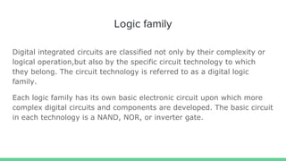


The document explains logic families in digital integrated circuits, which are classified by their technology and include types like TTL, CMOS, and ECL. It details characteristics of ideal logic families, such as low power and high speed, along with concepts of fan-in, fan-out, and propagation delay that are crucial for circuit functionality. The document also highlights that older families like diode logic and resistor transistor logic are now obsolete, while TTL, CMOS, and ECL are still widely used.