Downloaded 232 times


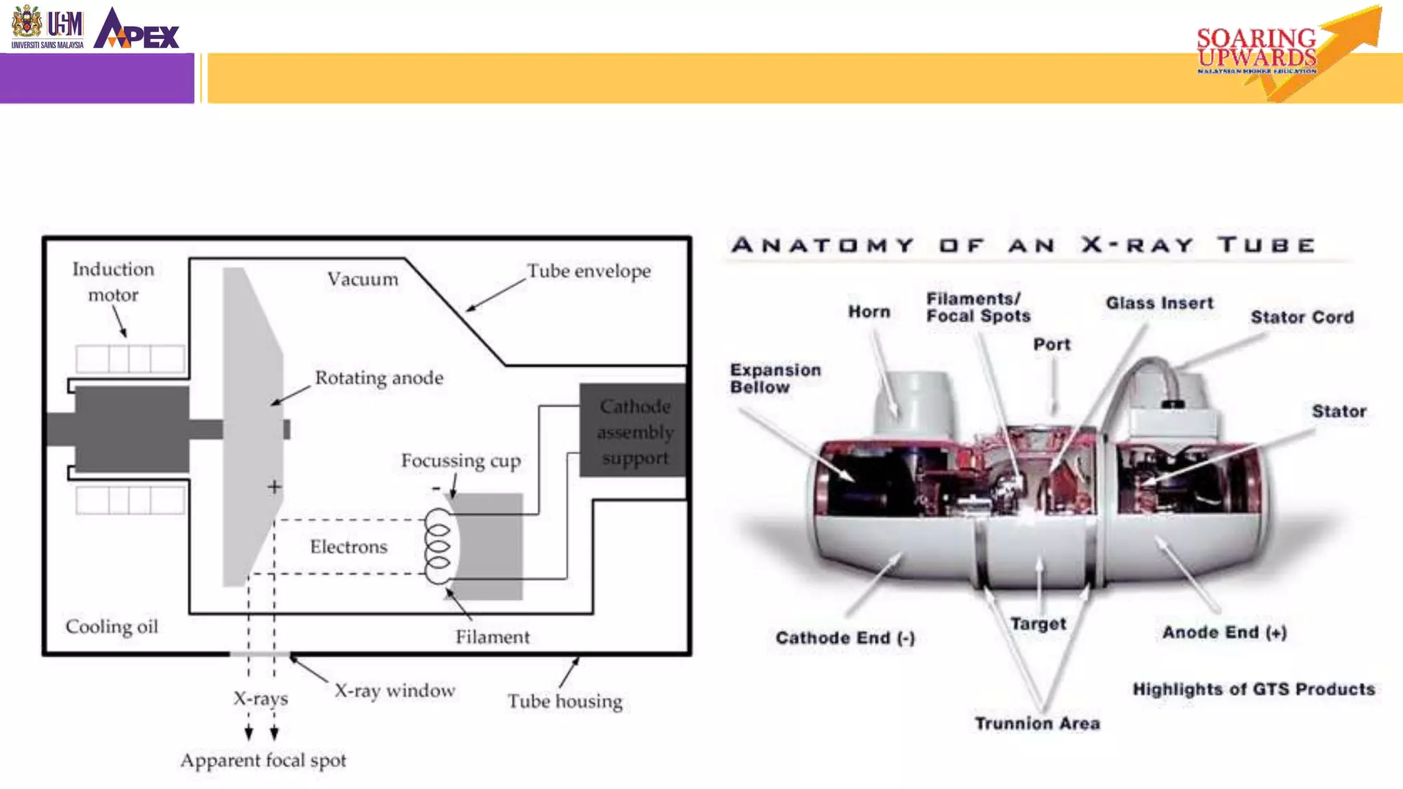


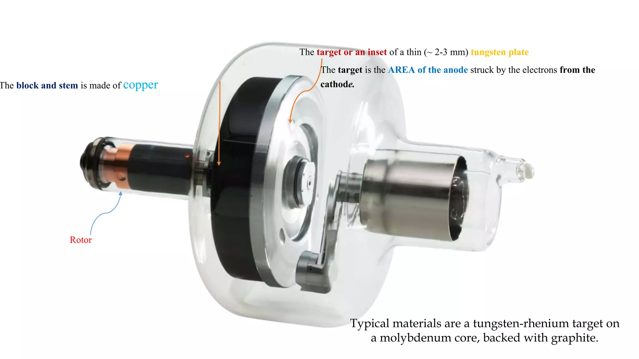

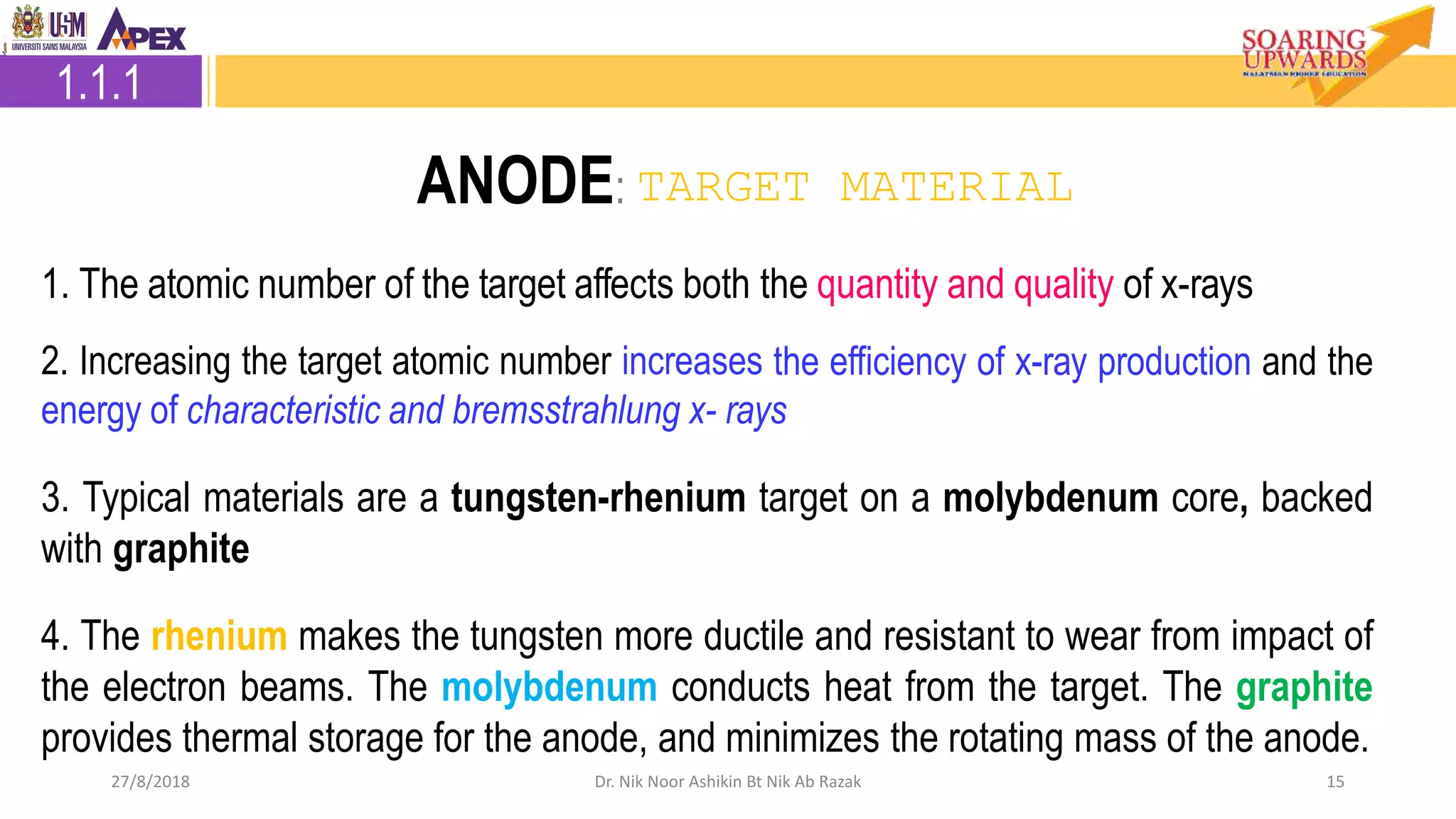
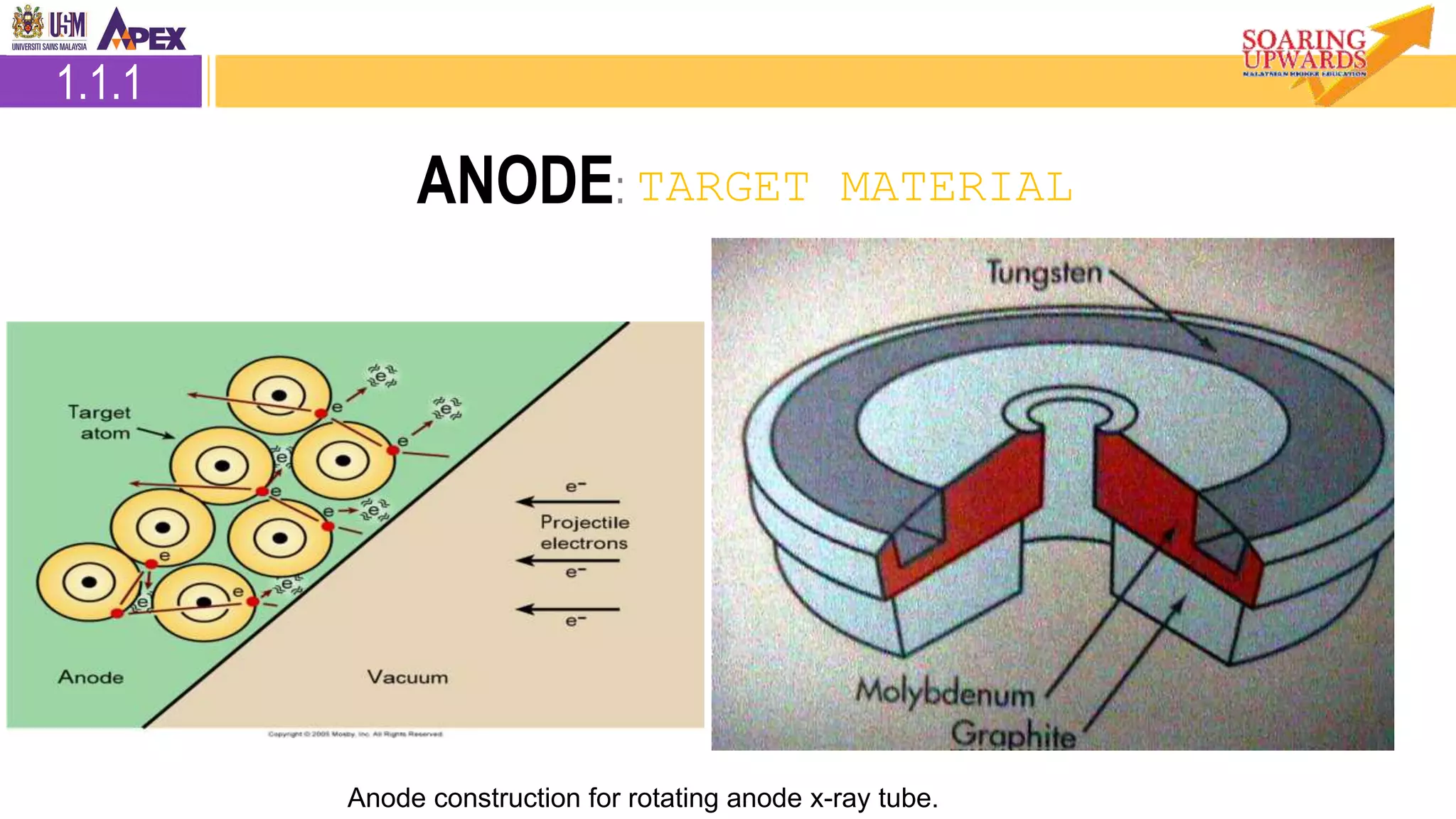

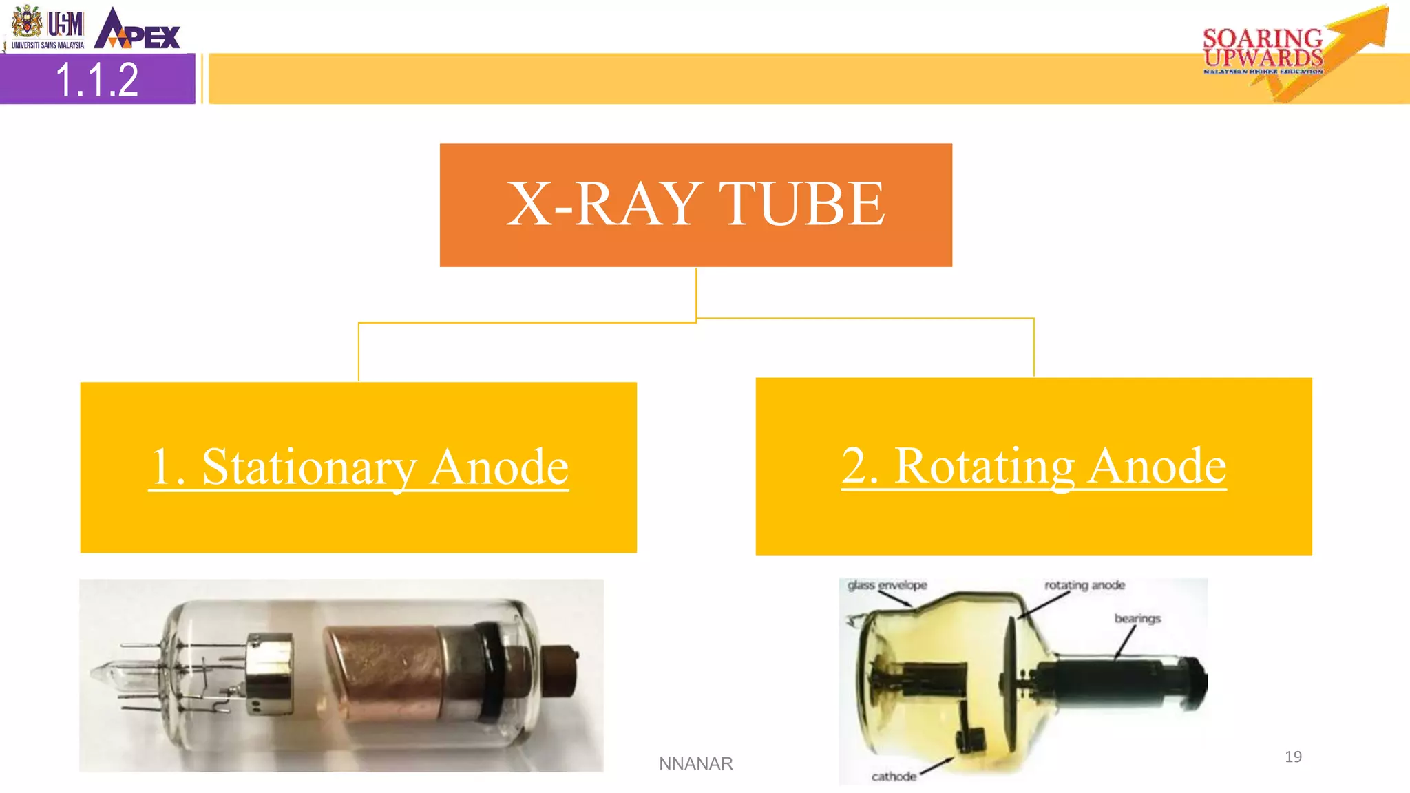

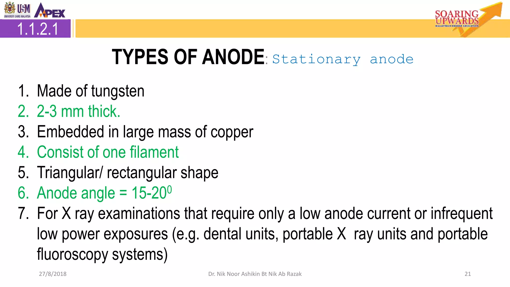
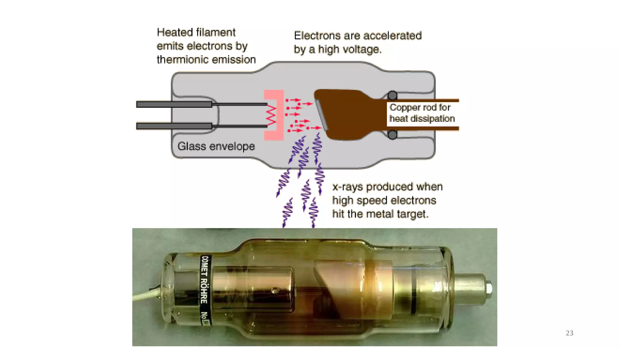

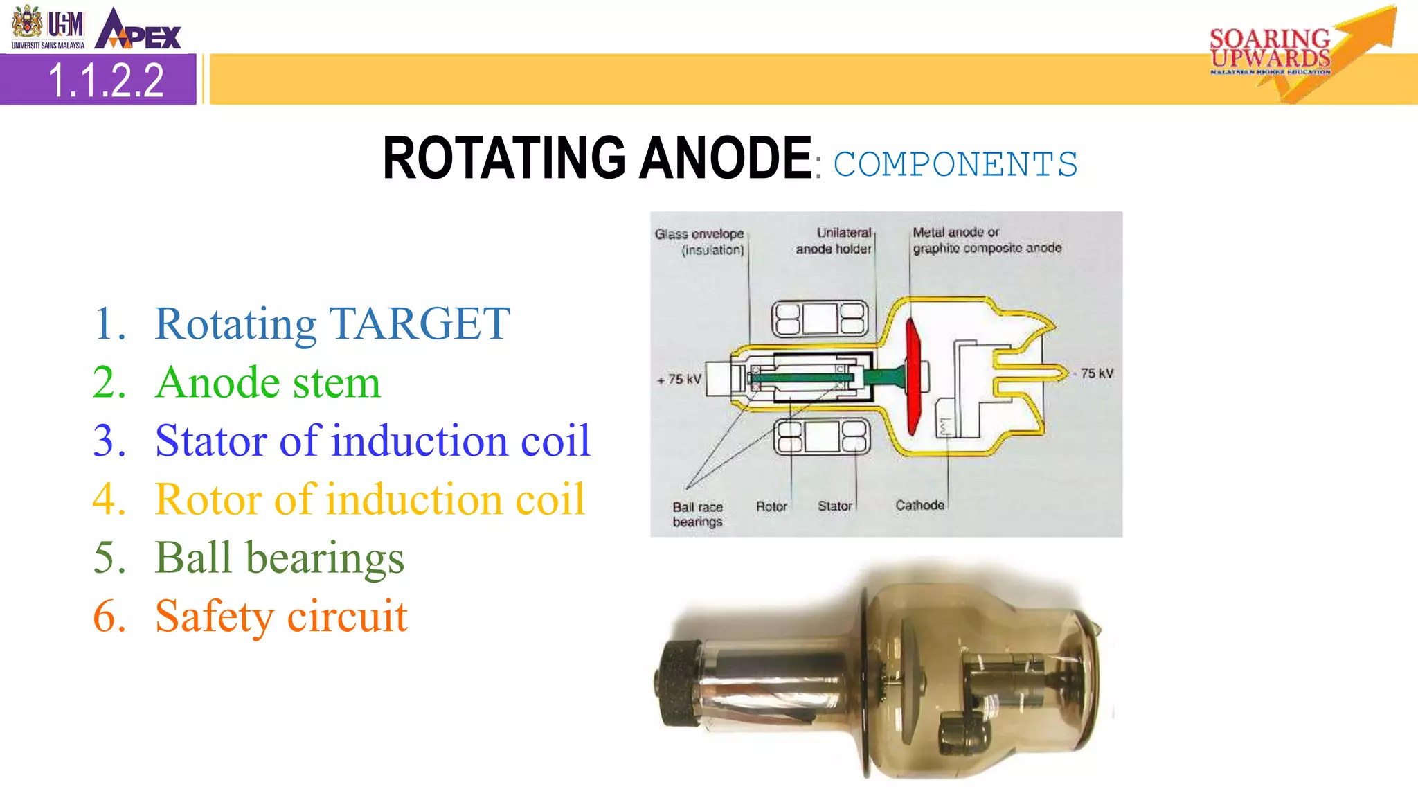

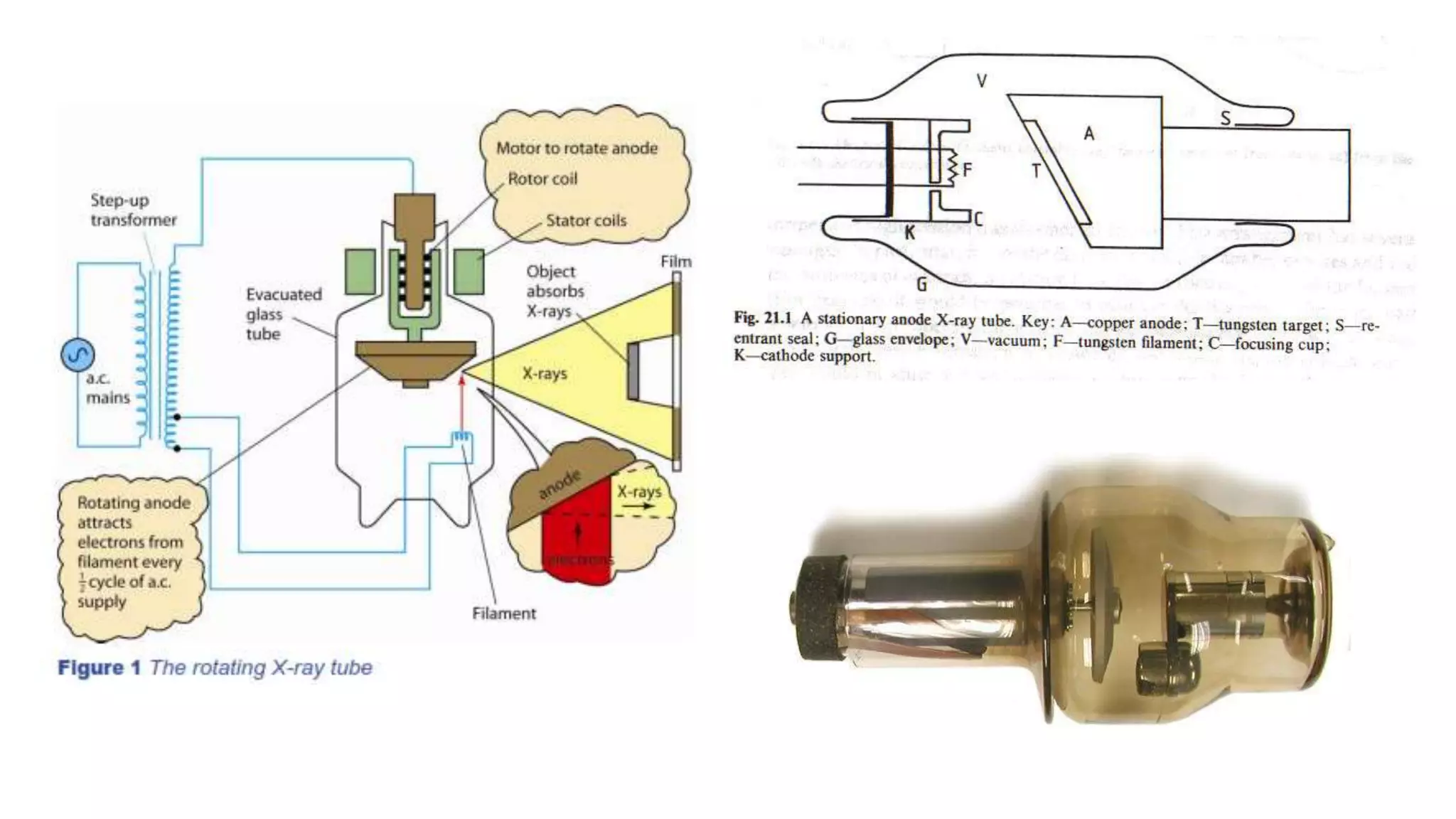
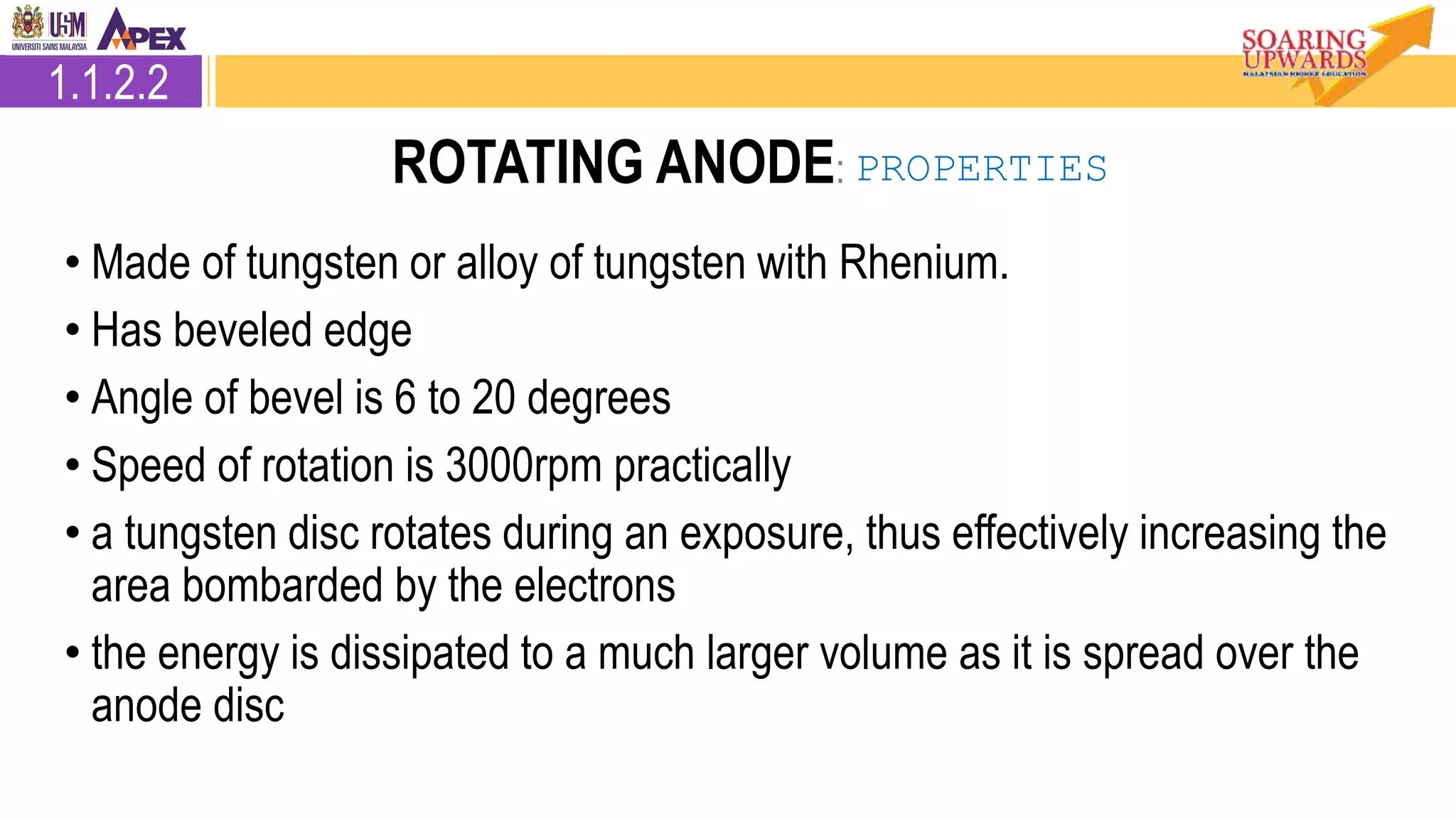
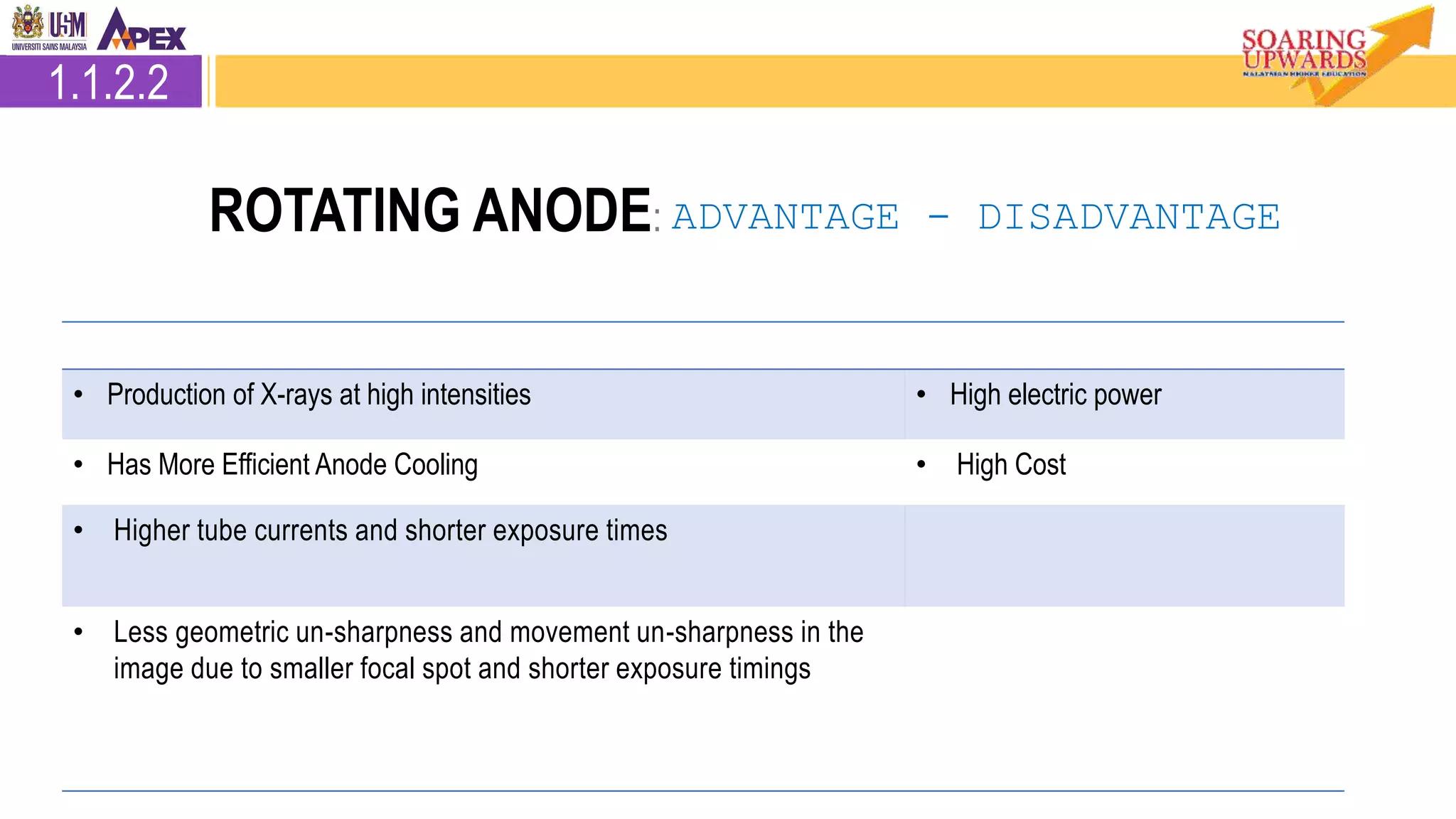

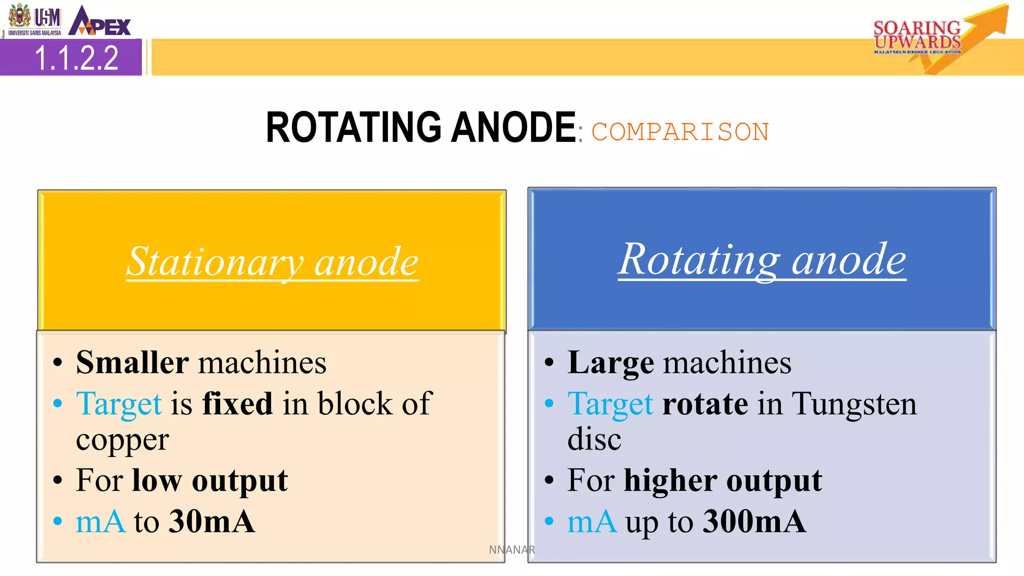

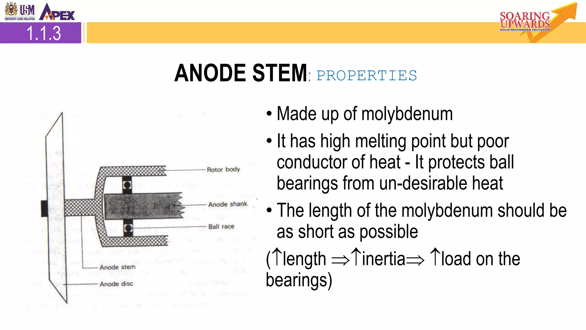


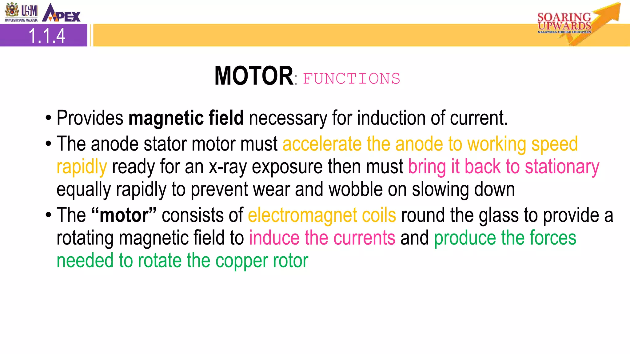

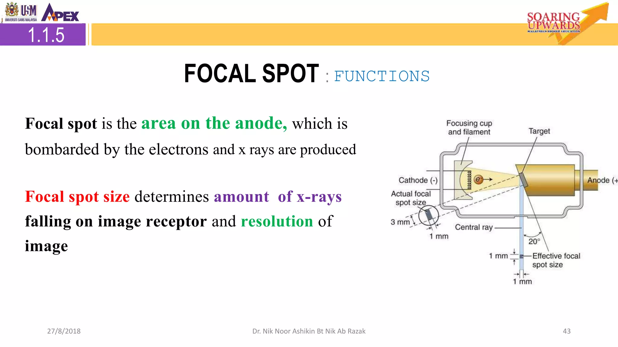


This document discusses the components and functioning of an X-ray tube. It describes the main parts of an X-ray tube including the anode, cathode, glass envelope and housing. It focuses on the anode in detail, explaining the target material, types of anodes (stationary and rotating), and other anode components like the stem, bearings, rotor and motor system, and focal spot. The functions and properties of each part are provided to explain how an X-ray tube works to produce X-ray radiation for medical applications.