Downloaded 257 times
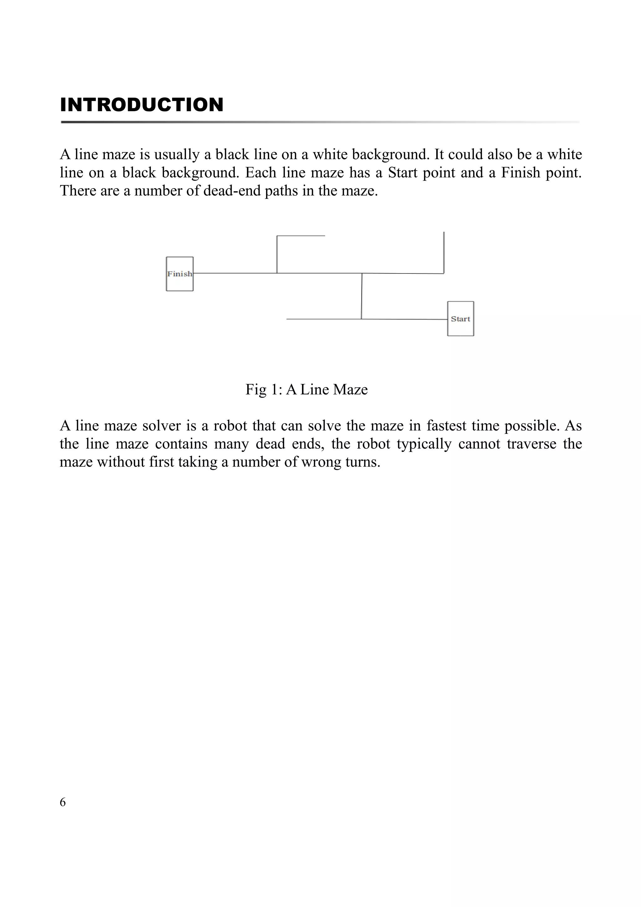
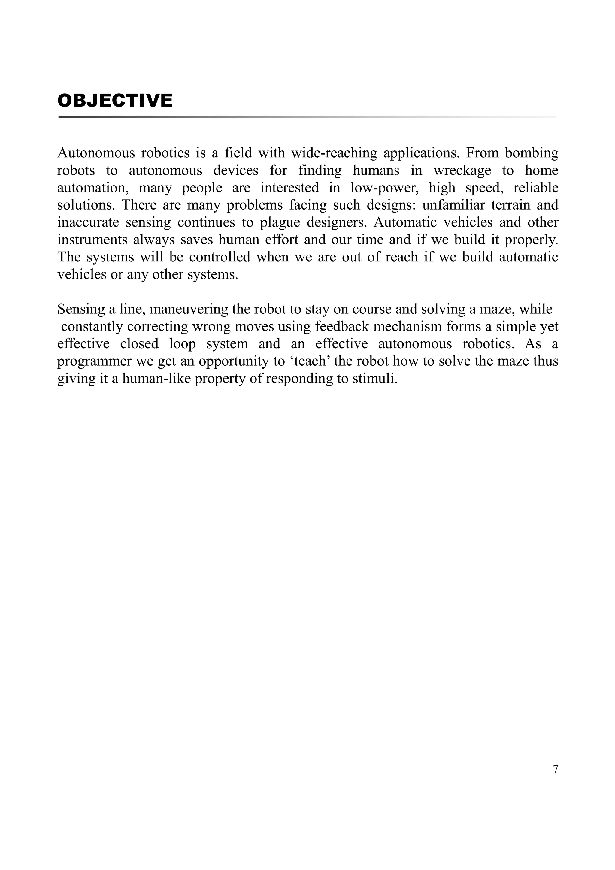
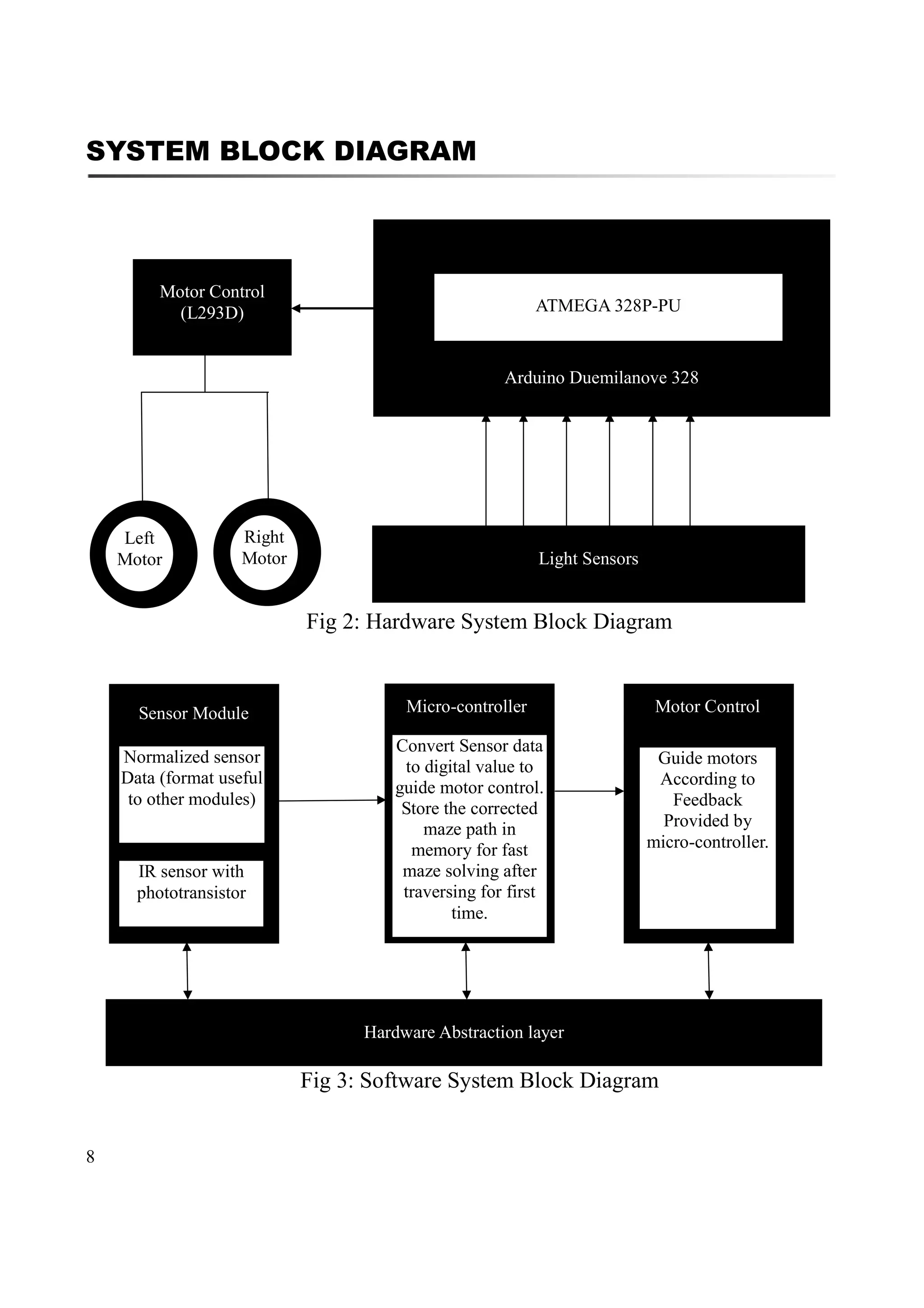
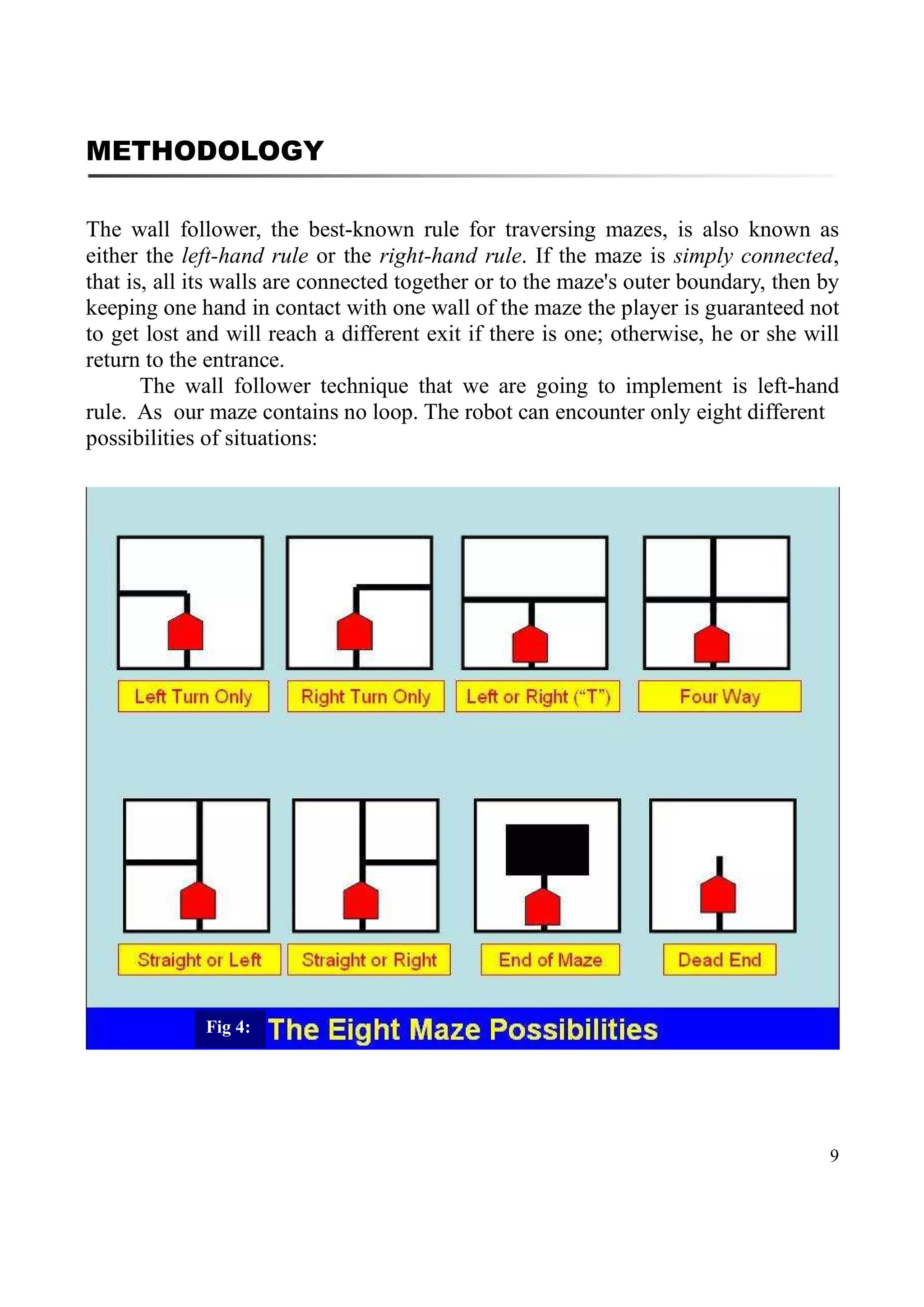
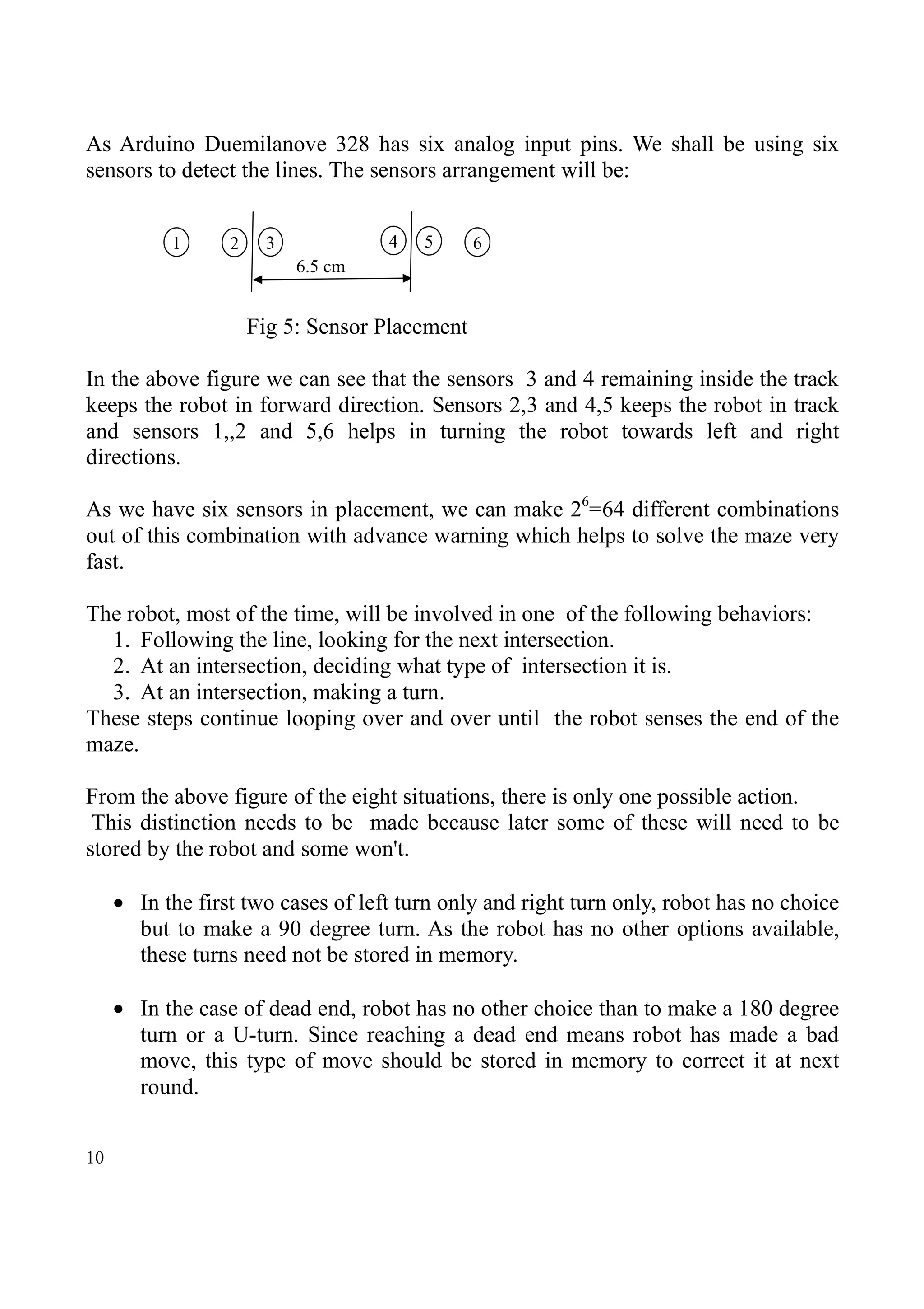

The document describes a proposal for a line maze solver robot project. It includes an introduction to line mazes, the objectives of the project to build an autonomous robot that can solve a line maze, and the key components and methodology. The robot will use 6 light sensors to detect the black line on a white surface and make decisions at intersections. It will use an Arduino microcontroller to process sensor input and control the motors. The first run will record wrong turns to avoid on the second run when it can solve the maze quickly.