Downloaded 129 times


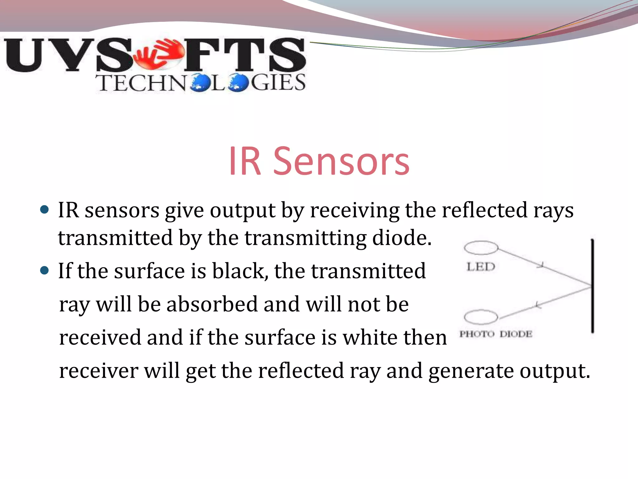
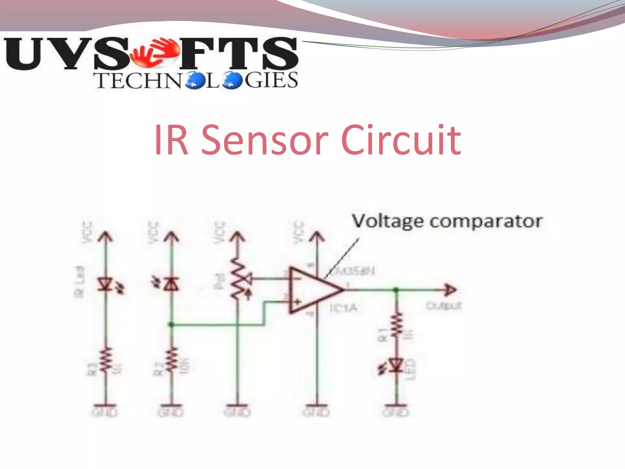
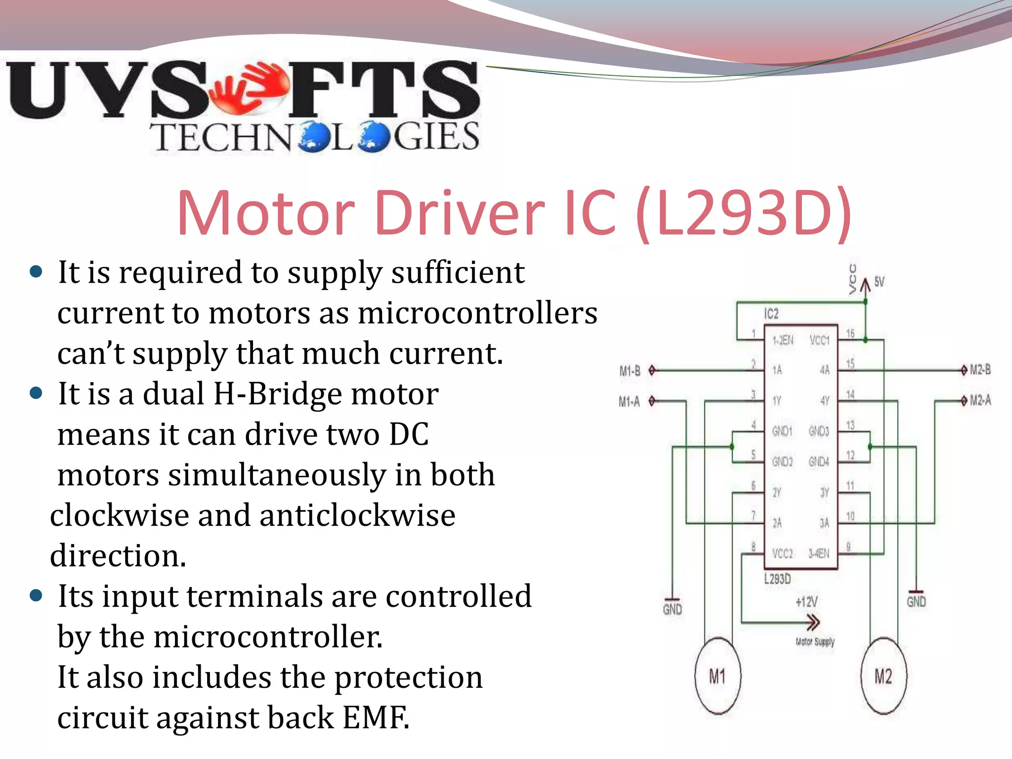
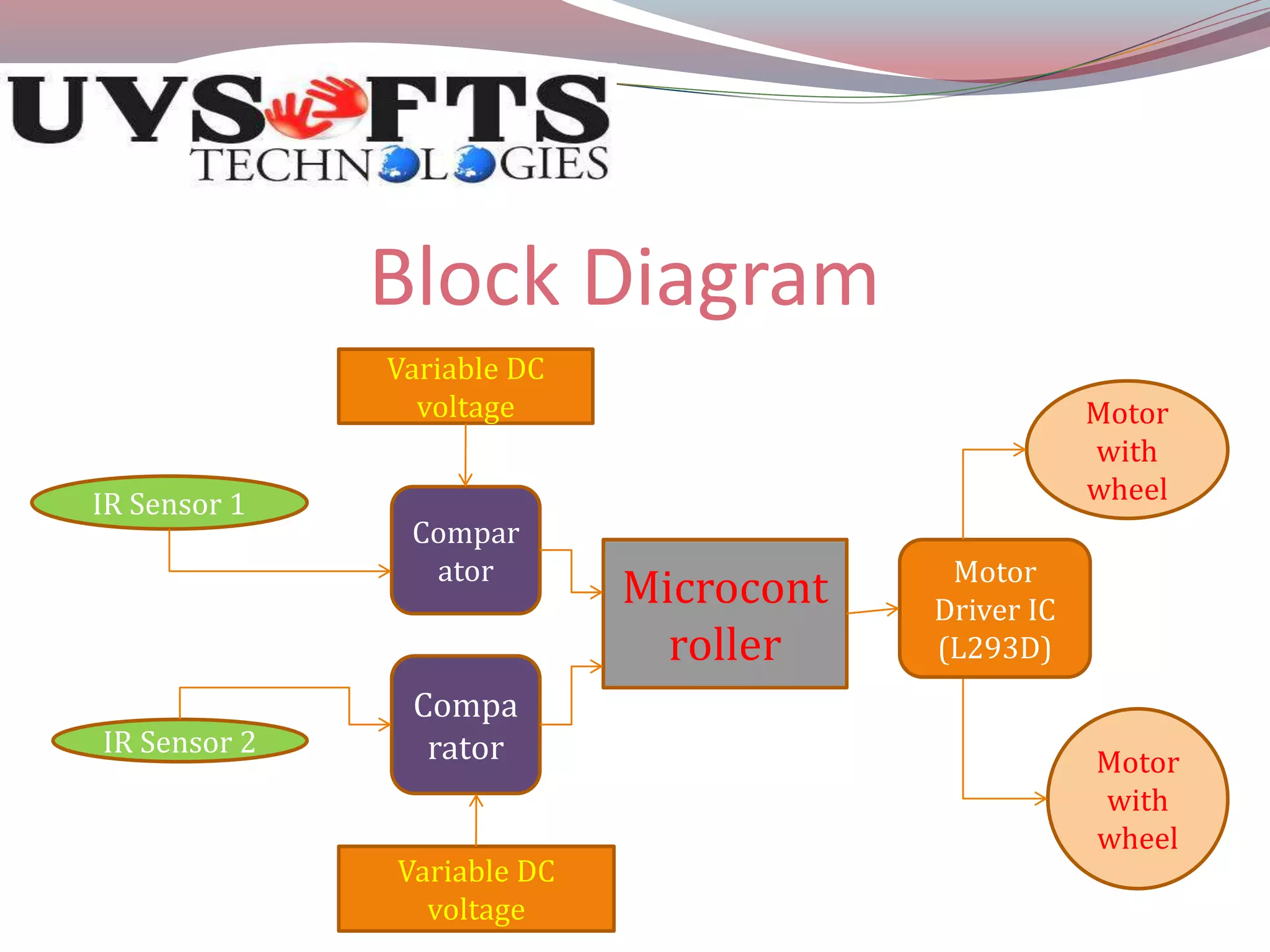
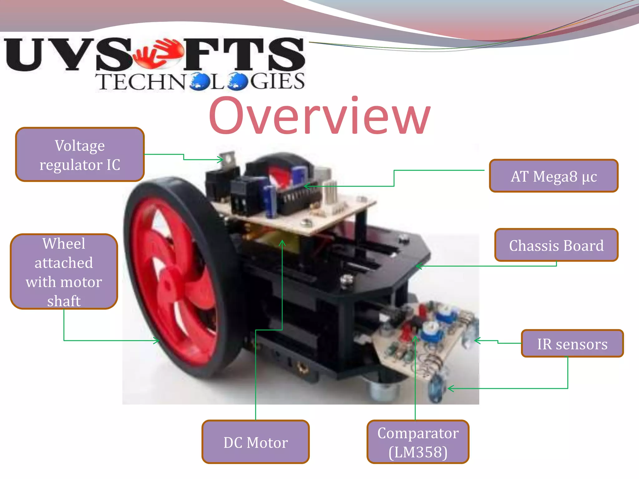
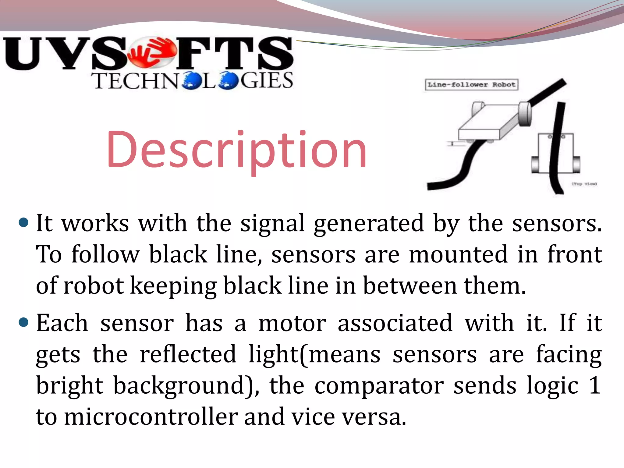
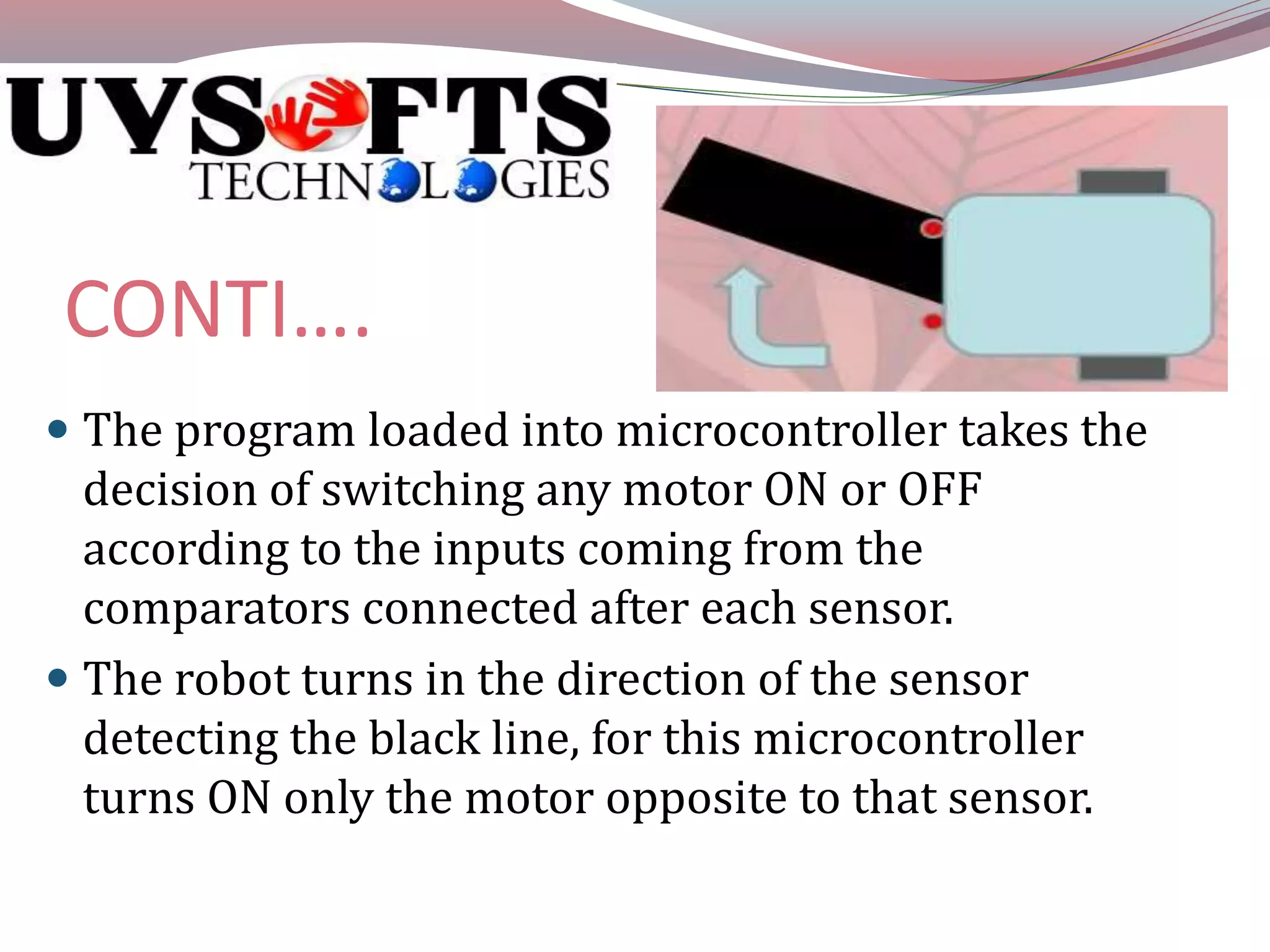


This document describes the design of a line-following robot that uses an ATMega8 microcontroller. The robot uses IR sensors to detect a black or white line and follow it, taking turns automatically. It includes IR sensors, a comparator IC, motor driver IC, DC motors, and a microcontroller board to process sensor input and control the motors accordingly to follow the line. The robot is able to detect the line with the IR sensors, send the sensor signals to the microcontroller via comparators, and have the microcontroller turn the appropriate motor on or off to steer the robot along the line.