Obstacle detection Robot using Ultrasonic Sensor and Arduino UNO
•Download as PPTX, PDF•
15 likes•13,910 views

This document describes how to build an obstacle detection robot using an Arduino UNO, ultrasonic sensor, and motor driver module. It explains the components used, including the Arduino, ultrasonic sensor to detect obstacles from 2-400cm away, and an L298N motor driver module to control DC motors. It provides details on connecting the components, programming the ultrasonic sensor to trigger and receive echo signals to determine distances, and controlling the motor's direction depending on detected obstacles to help the robot navigate. Code and more details are available at the provided GitHub link.

Recommended
More Related Content
What's hot
What's hot (20)
Viewers also liked
Viewers also liked (11)
Similar to Obstacle detection Robot using Ultrasonic Sensor and Arduino UNO
Similar to Obstacle detection Robot using Ultrasonic Sensor and Arduino UNO (20)
More from Sanjay Kumar
More from Sanjay Kumar (19)
Recently uploaded
Recently uploaded (20)
Obstacle detection Robot using Ultrasonic Sensor and Arduino UNO
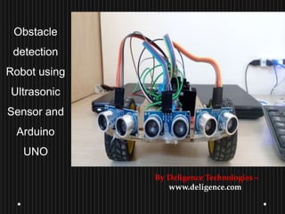
- 1. Obstacle detection Robot using Ultrasonic Sensor and Arduino UNO By Deligence Technologies – www.deligence.com
- 3. Components Used in this Project – Arduino UNO Ultrasonic Sensor (HC-SR04) Motor Driver Module (L298D) Controlling DC Motors Project Description Video Presentation
- 4. 1. Arduino UNO : Arduino/Genuino Uno is a microcontroller board based on the ATmega328P (datasheet). It has 14 digital input/output pins (of which 6 can be used as PWM outputs), 6 analog inputs, a 16 MHz quartz crystal, a USB connection, a power jack, an ICSP header and a reset button.
- 5. 2. Ultrasonic Sensor (HC-SR04) : Ultrasonic range sensor(HC - SR04) provides 2cm - 400cm distance measurement function, the ranging accuracy can reach to 3mm. The modules includes ultrasonic transmitters, receiver and control circuit.
- 6. 3. Motor Driver Module (L298D) : The L298N H-bridge module can be used with motors that have a voltage of between 5 and 35V DC. With the module used in this tutorial, there is also an onboard 5V regulator, so if your supply voltage is up to 12V you can also source 5V from the board.
- 7. 1. DC motor 1 “+” or stepper motor A+ 2. DC motor 1 “-” or stepper motor A- 3. 12V jumper – remove this if using a supply voltage greater than 12V DC. This enables power to the onboard 5V regulator 4. Connect your motor supply voltage here, maximum of 35V DC. Remove 12V jumper if >12V DC 5. GND 6. 5V output if 12V jumper in place, ideal for powering your Arduino (etc) 7. DC motor 1 enable jumper. Leave this in place when using a stepper motor. Connect to PWM output for DC motor speed control. 8. IN1 9. IN2 10. IN3 11. IN4 12. DC motor 2 enable jumper. Leave this in place when using a stepper motor. Connect to PWM output for DC motor speed control. 13. DC motor 2 “+” or stepper motor B+ 14. DC motor 2 “-” or stepper motor B-
- 8. 4. Controlling DC Motors : To control one or two DC motors is quite easy with the L298N H-bridge module. First connect each motor to the A and B connections on the L298N module. If you’re using two motors for a robot (etc) ensure that the polarity of the motors is the same on both inputs. Otherwise you may need to swap them over when you set both motors to forward and one goes backwards! Next, connect your power supply – the positive to pin 4 on the module and negative/GND to pin 5. If you supply is up to 12V you can leave in the 12V jumper (point 3 in the image above) and 5V will be available from pin 6 on the module. This can be fed to your Arduino’s 5V pin to power it from the motors’ power supply. Don’t forget to connect Arduino GND to pin 5 on the module as well to complete the circuit. Now you will need six digital output pins on your Arduino, two of which need to be PWM (pulse-width modulation) pins. PWM pins are denoted by the tilde (“~”) next to the pin number, for example:
- 9. Finally, connect the Arduino digital output pins to the driver module. In our example we have two DC motors, so digital pins D9, D8, D7 and D6 will be connected to pins IN1, IN2, IN3 and IN4 respectively. Then connect D10 to module pin 7 (remove the jumper first) and D5 to module pin 12 (again, remove the jumper). The motor direction is controlled by sending a HIGH or LOW signal to the drive for each motor (or channel). For example for motor one, a HIGH to IN1 and a LOW to IN2 will cause it to turn in one direction, and a LOW and HIGH will cause it to turn in the other direction. However the motors will not turn until a HIGH is set to the enable pin (7 for motor one, 12 for motor two). And they can be turned off with a LOW to the same pin(s). However if you need to control the speed of the motors, the PWM signal from the digital pin connected to the enable pin can take care of it.
- 11. Here we are going to implement a bot which is going to detect obstacle and according to that, it going to change its direction. For this we Require - • Arduino UNO • Ultrasonic Sensor • L298d • Dc gear Motor Now first we are going to connect all ultrasonic sensor with our Arduino board. Then according to program our all ultrasonic sensor going generate a trigger signal which is going to receive by our echo pin of Ultrasonic Sensor. Then we are going to run an algorithm according which we are going to manipulate our desire distance for obstacle detection then we are going to control our motor rotation direction for movement of our bot.
- 12. 50CM(Front),15CM (Each Side) You can check it's code & detailed description at - https://github.com/DeligenceTechnologies/Obstacle-detection-Robot-using- Ultrasonic-Sensor-and-Arduino-UNO . You can contact us at info [@] deligence.com in case you have any query. You can also contact us at sales [@] deligence.com in case of any Development requirement.
- 13. Deligence Technologies - your growing technology partner! www.deligence.com/contact-us Email : info@deligence.com Phone : +91 9910130340