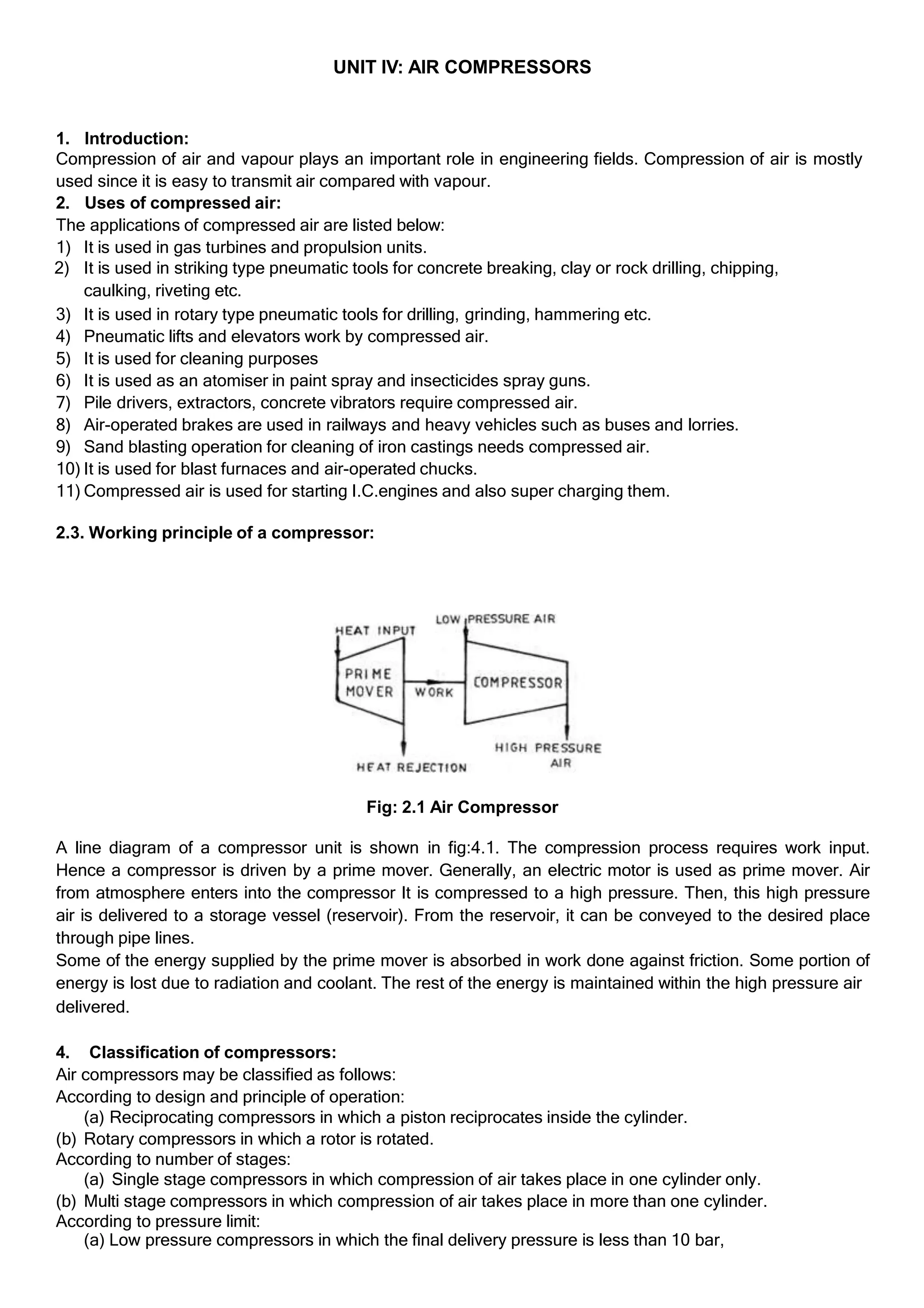
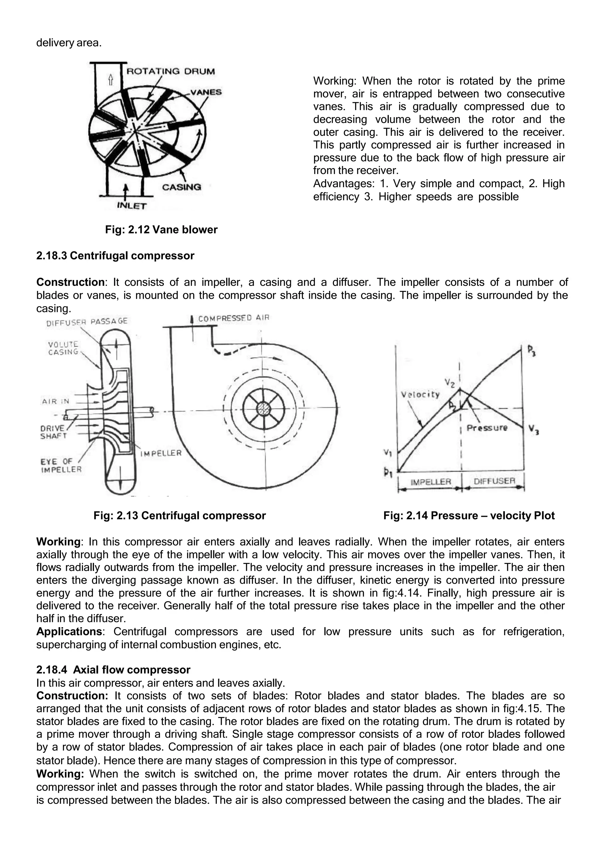
The document discusses air compressors, emphasizing their importance in engineering, various applications, and working principles. It classifies air compressors based on design, pressure limits, capacity, and cooling methods, detailing single-stage and multi-stage types. Furthermore, it explores compression processes, power requirements, efficiency metrics, and the effects of clearance volume on compressor performance.

![Let,
p1 = Pressure of the air (kN/m2
), before compression
V 1 = Volume of the air (m3
), before compression
T1 =Temperature of the air (K), before compression
p2, V2 and T2 be the corresponding values after compression.
m - Mass of air induced or delivered by the cycle (kg).
N - Speed in RPM.
2.7.1Polytropic Compression
Fig:2.4 Polytropic compression
(Compression follows pVn
= Constant)
Let n= Index of polytropic compression
Net work done on air/cycle is given by
W = Area 1-2-3-4-1
= Work done during compression (1-2) + Work done during air delivery (2-3) - Work done during
suction (4-1).
W =
𝑝 𝑣 −𝑝 𝑣
2 2 1 1
𝑛−1
+ 𝑝 𝑣 − 𝑝 𝑣
2 2 1 1
𝑝2𝑣2− 𝑝1+(𝑛−1)𝑝2𝑣2− (𝑛−1)𝑝1𝑣1
W =
𝑛−1
𝑛𝑝2𝑣2− 𝑛𝑝1𝑣1
𝑛−1
𝑛
𝑛−1
= = ( ) 𝑝2𝑣2 − 𝑝1𝑣1
We know that, p1V1 = m RT1 & p2V2 = m RT2
𝒏
𝒏−𝟏
Therefore, W = m R (T2 - T1)
𝒏
𝒏−𝟏 𝑻𝟏
W = m R T1 [𝑻𝟐
− 𝟏]
𝑝2
𝑇1 𝑝1
For polytropic process, 𝑇2
= ( )
𝑛−1
𝑛
𝑛
𝑛−1 𝑝1
𝑛−1
𝑝2 𝑛
Therefore, W = m R T1 [( ) − 1] kJ/cycle
𝑛
𝑛−1 𝑝1
𝑛−1
𝑝2 𝑛
W = p1 V1 [( ) − 1] kJ/cycle
Indicated power (or) Power required, P = W x N , kW for single acting reciprocating compressor;](https://image.slidesharecdn.com/aircompressors-240502062927-0e2251a6/75/UNIT-IV-Air-Compressors-and-its-Performance-4-2048.jpg)
![= W x 2N, kW for double acting reciprocating compressor.
2.7.2 Isentropic compression
Compression follows, p𝑽𝛾= Constant
Let 𝛾 = Index of isentropic compression
Net work done on air/cycle is given by
W = Area 1-2-3-4-1
= Work done during compression (1-2) + Work done during air delivery (2-3) - Work done during
suction (4-1).
W =
𝑝 𝑣 −𝑝 𝑣
2 2 1 1
𝛾−1
+ 𝑝 𝑣 − 𝑝 𝑣
2 2 1 1
W = 𝑝2𝑣2− 𝑝1+(𝛾−1)𝑝2𝑣2− (𝛾−1)𝑝1𝑣1
𝛾−1
=𝛾𝑝2𝑣2− 𝛾𝑝1𝑣1 𝛾
𝛾−1 𝛾−1
= ( ) 𝑝 𝑣 − 𝑝 𝑣
2 2 1 1
We know that, p1V1 = m RT1 & p2V2 = m RT2
𝜸
𝜸−𝟏
W = m R (T2 - T1)
𝜸
𝜸−𝟏 𝑻𝟏
W = m R T1 [𝑻𝟐
− 𝟏]
𝑇1 𝑝1
For isentropic process, 𝑇2
= ( )
𝛾−1
𝑝2 𝛾
𝜸
1
𝜸−𝟏 𝑝1
𝛾−1
𝑝2 𝛾
Therefore, W = m R T [( ) − 1] kJ/cycle
𝜸
1 1
𝜸−𝟏 𝑝1
W = p V [(
𝑝2
)
𝛾
− 1] kJ/cycle
𝛾−1
2.7.3 Isothermal Compression
Compression follows, pV= Constant
Fig: 2.5 Isothermal Compression
Isothermal Work input, W = Area 1-2-3-4-1 = area under 1-2 + area under 2-3 - area under 4-1
𝑉1
𝑉2
W = 𝑝 𝑉 𝑙𝑛 ( ) + 𝑝 𝑉 − 𝑝 𝑉
1 1 2 2 1 1
But 𝑝1𝑉1 = 𝑝2𝑉2
𝑉1
𝑉2
W= 𝑝1𝑉1 𝑙𝑛 ( ) 𝑎𝑛𝑑 =
𝑉1 𝑝2
𝑉2 𝑝1](https://image.slidesharecdn.com/aircompressors-240502062927-0e2251a6/75/UNIT-IV-Air-Compressors-and-its-Performance-5-2048.jpg)

![𝑛
𝑛−1
1 1
𝑝1
𝑝2 𝑛
W = p V [( ) 𝑛−1
4
𝑝3
𝑝4
Fig: 2.6 p-V diagram with clearance volume
2.11.3 Work input considering clearance volume:
Assuming the expansion (3-4) and compression (1-2) follow the law p Vn
= C,
Work input per cycle is given by,
W = Area (1-2-3-6-5-4-1)- Area (3-6-5-4 -3)
W = Workdone during compression - Work done during expansion
𝑛−1 𝑛−1
𝑛 𝑛
− 1] - p V4 [( ) − 1]
𝑛
𝑛−1
1 1
𝑝1
But, p3 = p2 and p4 = p1
therefore
𝑛−1
𝑝2 𝑛
W = p V [( )
𝑛
𝑛−1
1
𝑝2
𝑝1
𝑛−1
𝑛
− 1] - p V4 [( ) − 1]
𝑛
𝑛−1
1 1 4
𝑝2
𝑝1
𝑛−1
𝑛
W = p (V – V ) [( ) − 1] kJ/cycle
V1-V4 is called as effective suction volume.
2.12 Volumetric efficiency:
The clearance volume in a compressor reduces the intake capacity of the cylinder. This leads to a term
called volumetric efficiency.
The volumetric efficiency is denned as the volume of free air sucked into the compressor per cycle to the
stroke volume of the cylinder,the volume measured at the intake pressure and temperature or at standard
atmospheric conditions,(ps =101.325 kN/m2
and Ts = 288K)
Volumetric efficiency, ηvol =
Volume of free air taken in per cycle
Stroke volume of the cylinder
= Swept volume (𝑉1 – 𝑉3)
Effective suction volume
= (𝑉1 − 𝑉4)
=
𝑉1−𝑉4
𝑉𝑠](https://image.slidesharecdn.com/aircompressors-240502062927-0e2251a6/75/UNIT-IV-Air-Compressors-and-its-Performance-7-2048.jpg)
![Clearance ratio: Clearance ratio is defined as, the ratio of clearance volume to swept volume. It is denoted
by the letter C.
𝑆𝑤𝑒𝑝𝑡 𝑣𝑜𝑙𝑢𝑚𝑒 𝑉𝑠
Clearance ratio,C = 𝐶𝑙𝑒𝑎𝑟𝑎𝑛𝑐𝑒 𝑣𝑜𝑙𝑢𝑚𝑒
= 𝑉𝑐
=
𝑉𝑐
𝑉1−𝑉3
Pressure ratio, Rp = 𝐷𝑒𝑙𝑖𝑣𝑒𝑟𝑦 𝑝𝑟𝑒𝑠𝑠𝑢𝑟𝑒
= 𝑝2
= 𝑝3
𝑆𝑢𝑐𝑡𝑖𝑜𝑛 𝑝𝑟𝑒𝑠𝑠𝑢𝑟𝑒 𝑝1 𝑝4
2.12.1 Expression for Volumetric efficiency
Let the compression and expansion follows the law, pVn
=Constant.
𝑆𝑤𝑒𝑝𝑡 𝑣𝑜𝑙𝑢𝑚𝑒 𝑉𝑠
Clearance ratio, C = 𝐶𝑙𝑒𝑎𝑟𝑎𝑛𝑐𝑒 𝑣𝑜𝑙𝑢𝑚𝑒
= 𝑉𝑐
=
𝑉3
𝑉1−𝑉3
1 3
V -V =
𝑉3
𝐶
-------------(1)
𝐶
V1 = 𝑉3
+ V3
1
1
𝐶
V = V3 ( + 1) --------------------- (2)
We know that, Pressure ratio, Rp = 𝐷𝑒𝑙𝑖𝑣𝑒𝑟𝑦 𝑝𝑟𝑒𝑠𝑠𝑢𝑟𝑒
= 𝑝2
= 𝑝3
𝑆𝑢𝑐𝑡𝑖𝑜𝑛 𝑝𝑟𝑒𝑠𝑠𝑢𝑟𝑒 𝑝1 𝑝4
By polytropic expansion process 3-4:
𝑝3
= 𝑉4
𝑝4 𝑉3
( )
𝑛
𝑝
𝑉4
= ( 3
)
𝑉3 𝑝4
1/𝑛 1
= (𝑅𝑝)𝑛
1
Therefore, 𝑉4 = V3(𝑅𝑝)𝑛
----------------- (3)
vol
Volumetric efficiency, η =
Effective suction volume
Swept volume
(𝑉1− 𝑉4)
=
(𝑉1– 𝑉3)
------------ (4)
Using equations 1,2 and 3 in 4,
vol
η =
1
𝑉3(𝐶
+1)−𝑉3[𝑅𝑝 ]
1/𝑛
𝑉3
𝐶
=
1 1/𝑛
𝑉3 (𝐶
+1)−[𝑅𝑝 ]
1
𝑉3(𝐶
)
=
1
𝐶 𝑝
( +1)−[𝑅 ]
1/𝑛
1
(𝐶
)
1
𝐶
1/𝑛
= C[( + 1) − [𝑅𝑝] ]
ηvol
1/𝑛 𝑝
𝑝1
= 1+ C - C[𝑅𝑝 ] = 1+ C – C[ 2
]
1/𝑛
2.13 Multi-stage air compressor:
In a multi stage air compressor, compression of air takes place in more than one cylinder. Multi
stage air compressor is used in places where high pressure air is required. Fig. shows the general
arrangement of a two-stage air compressor. It consists of a low pressure (L.P) cylinder, an intercooler and
a high pressure (H.P) cylinder. Both the pistons (in L.P and H.P cylinders) are driven by a single prime
mover through a common shaft.
Atmospheric air at pressure p1 taken into the low pressure cylinder is compressed to a high
pressure (p2). This pressure is intermediate between intake pressure (p1) and delivery pressure p3).
Hence this is known as intermediate pressure.
The air from low pressure cylinder is then passed into an intercooler. In the intercooler, the air is
cooled at constant pressure by circulating cold water. The cooled air from the intercooler is then taken into
the high pressure cylinder. In the high pressure cylinder, air is further compressed to the final delivery
pressure (p3) and supplied to the air receiver tank.](https://image.slidesharecdn.com/aircompressors-240502062927-0e2251a6/75/UNIT-IV-Air-Compressors-and-its-Performance-8-2048.jpg)
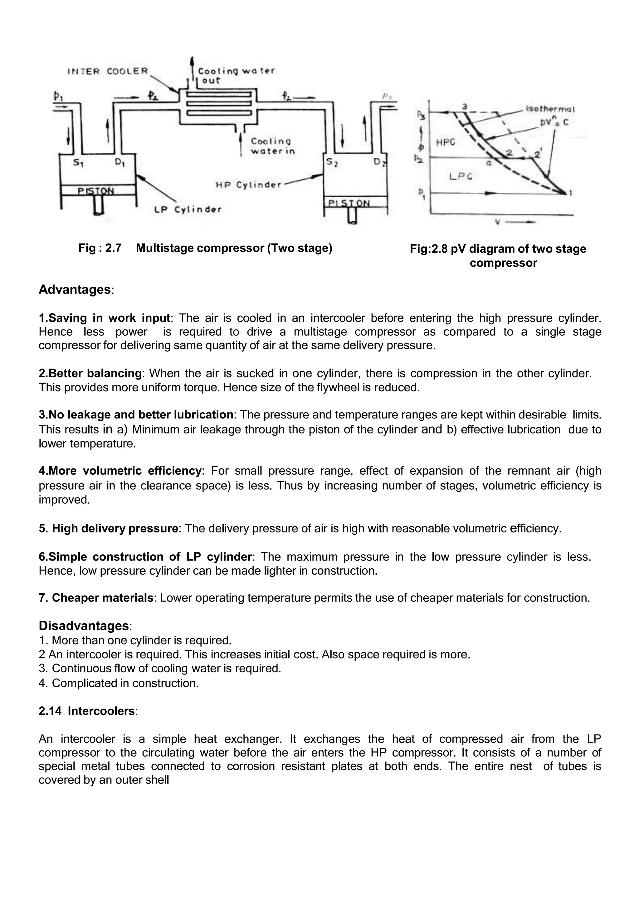
![Working: Cold water enters the bottom of the
intercooler through water inlet (1) and flows into the
bottom tubes. Then they pass through the top tubes
and leaves through the water outlet (2) at the top. Air
from LP compressor enters through the air inlet (3)
of the intercooler and passes over the tubes. While
passing over the tubes, the air is cooled (by the cold
water circulated through the tubes). This cold air
leaves the intercooler through the air outlet (4). Baffle
plates are provided in the intercooler to change the
direction of air. This provides a better heat transfer
from air to the circulating water.
Fig:2.9 Intercooler
2.15 Work input required in multistage compressor:
The following assumptions are made for calculating
the work input in multistage compression.
1.Pressure during suction and delivery remains
constant in each stage.
2.Intercooling takes place at constant pressure in
each stage.
3. The compression process is same for each stage.
4.The mass of air handled by LP cylinder and HP
cylinder is same.
5. There is no clearance volume in each cylinder.
6 There is no pressure drop between the two stages,
i.e., exhaust pressure of one stage is equal to the
suction pressure of the next stage. Fig:2.10 Two Stage compression
Work required to drive the multi-stage compressor can be calculated from the area of the p - V diagram .
Let, p1,V1 and T1 be the condition of air entering the LP cylinder.
P2, V2 and T2 be the condition of air entering the HP cylinder.
p3 be the final delivery pressure of air.
Then,
Total work input = Work input for LP compressor + Work input for HP compressor.
𝑛
1 1
𝑛−1 𝑝1
𝑛−1
𝑝2 𝑛
W = p V [( ) − 1] +
𝑛
𝑛−1
1 1
𝑝2
𝑛−1
𝑝3 𝑛
p V [( ) − 1] kJ/cycle
𝑛
1
𝑛−1 𝑝1
𝑛−1
𝑝2 𝑛
W = m R T [( ) − 1] +
𝑛
𝑛−1
2
𝑝2
𝑛−1
𝑝3 𝑛
m R T [( ) − 1] kJ/cycle
If intercooling is perfect, T2 = T1, therefore,
𝑛
𝑛−1
𝑝2
𝑝1
𝑛−1
𝑛
W = m R T1[( ) − 1] +
𝑛
𝑛−1
𝑝3
𝑝2
𝑛−1
𝑛
m R T1[( ) − 1] kJ/cycle
𝑛
𝑛−1 𝑝1 𝑝2
𝑛−1 𝑛−1
W = m R T1[(𝑝2
) 𝑛
+ (𝑝3
) 𝑛
− 2] kJ/cycle](https://image.slidesharecdn.com/aircompressors-240502062927-0e2251a6/75/UNIT-IV-Air-Compressors-and-its-Performance-10-2048.jpg)
![Or
𝑛 𝑝2
1
𝑛−1
𝑛
𝑝2
𝑛−1
𝑝3 𝑛
W = p1V1 [( ) + ( ) − 2] kJ/cycle
𝑛−1 𝑝
1
𝑛 𝑝2 𝑝3
𝑝2
2.16 Condition for maximum efficiency (or)
Condition for minimum work input (or)
To prove that for minimum work input the intermediate pressure of a two-stage compressor with
perfect intercooling is the geometric mean of the intake pressure and delivery pressure (or)
To prove 𝒑𝟐 = √𝒑𝟏 𝒑𝟑
Work input for a two-stage air compressor with perfect intercooling is given by,
𝑛−1 𝑛−1
𝑛 𝑛
W = p1V1 [( ) + ( ) − 2] kJ/cycle
𝑛−1 𝑝
If the initial pressure (p1) and final pressure (p3) are fixed, the value of intermediate pressure (p2) can be
determined by differentiating the above equation of work input in terms of p2 and equating it to zero.
𝑛
1 1
𝑛−1 𝑛
Let, 𝑝 𝑉 = 𝑘 (𝑐𝑜𝑛𝑠𝑡𝑎𝑛𝑡) and
𝑛−1
= 𝑎
then,
𝑝
𝑝1
𝑝
𝑝2
𝑎 𝑎
W = 𝑘 [( 2) + ( 3) − 2]
or
W = 𝑘(𝑝𝑎 𝑝−𝑎 + 𝑝𝑎 𝑝−𝑎 − 2) -------------------- (1)
2 1 3 2
Differentiating the above equation (1) with respect to p2 and equating it to zero,
𝑑𝑊
𝑑𝑝2
2 1
= 𝑘 𝑎 𝑝 𝑝 + 𝑘 (–𝑎)𝑝 𝑝
3 2
𝑎−1 −𝑎 𝑎 −𝑎−1
= 0
𝑝𝑎
1
1
2
𝑝2𝑝𝑎 3
𝑝𝑎 𝑝2
𝑘 𝑎 2
− 𝑘 𝑎 𝑝𝑎 = 0
or
𝑘 𝑎 𝑝𝑎
1
𝑝2 𝑝𝑎
2
= 3
𝑘 𝑎 𝑝𝑎
2
𝑝2 𝑝𝑎
𝑝2
𝑝1
( )
𝑝3
𝑝2
𝑎
= ( )
𝑎
𝑜𝑟
𝑝2
= 𝑝3
𝑝1 𝑝2
2
=> 𝑝2 = 𝑝1𝑝3
𝑜𝑟
intermediate pressure, 𝐩𝟐 = √𝐩𝟏𝐩𝟑
Thus for maximum efficiency the intermediate pressure is the geometric mean of the initial and final
pressures.](https://image.slidesharecdn.com/aircompressors-240502062927-0e2251a6/75/UNIT-IV-Air-Compressors-and-its-Performance-11-2048.jpg)
![2.17 Minimum work input for multistage compression with perfect intercooling:
Work input for a two-stage compressor with perfect intercooling is given by
𝑝1
𝑛 𝑝2 𝑝3
𝑝2
𝑛−1 𝑛−1
𝑛 𝑛
W = p1V1 [( ) + ( ) − 2] ------------------------ (1)
𝑛−1
𝑝1 𝑝2
𝑝2 𝑝3
Work input will be minimum if = ------------------------------ (2)
2
𝑝2 = 𝑝1 𝑝3
1
Dividing both sides by 𝑝2 ,
𝑝1
2
( 2
) = 3
𝑝1
𝑝 𝑝 𝑝2 𝑝3
𝑝1 𝑝1
1/2
= ( ) -------------------------------- (3)
𝑝3 𝑝2 𝑝3
𝑝2 𝑝1 𝑝1
1/2
From (2), = = ( ) --------------------------------------- (4)
Substituting the equation (4) in equation (1), work input for a two stage compressor,
𝑛 𝑝3
𝑝1
𝑊𝑚𝑖𝑛 = 𝑛−1
p1V1 [( )
½ 𝑛
[ ]
𝑝3
𝑝1
+ ( )
𝑛−1 𝑛−1
½ 𝑛
[ ]
− 2]
=
𝑛
𝑛 − 1 1 1
𝑝3
𝑝1
𝑛−1
2𝑛
p V [2 ( ) − 2]
𝑚𝑖𝑛
𝑊 =
2𝑛
𝑛 − 1 1 1
𝑝3
𝑝1
𝑛−1
2𝑛
p V [( ) − 1]
𝑜𝑟
2𝑛 𝑝3
𝑝1
𝑛−1
2𝑛
𝑊𝑚𝑖𝑛 =
𝑛 − 1
𝑚RT1 [( ) − 1]
For a three stage compressor,
𝑊𝑚𝑖𝑛 =
3𝑛
𝑛 − 1 1 1
𝑝4
𝑝1
𝑛−1
3𝑛
p V [( ) − 1]
𝑜𝑟
3𝑛 𝑝4
𝑛−1
3𝑛
𝑊𝑚𝑖𝑛 =
𝑛 − 1
𝑚RT1 [( ) − 1]
𝑥𝑛 𝑝𝑥+1
𝑝1
Generally, the minimum work input for a multistage reciprocating air compressor with 𝑥 number of stages
is given by,
𝑛−1
𝑥𝑛
𝑊𝑚𝑖𝑛 =
𝑛 − 1
𝑝1V1 [(
𝑝
) − 1]
1
Minimum work input required for a two stage reciprocating air compressor with perfect intercooling is given
by,](https://image.slidesharecdn.com/aircompressors-240502062927-0e2251a6/75/UNIT-IV-Air-Compressors-and-its-Performance-12-2048.jpg)
![2𝑛 𝑝3
𝑝1
𝑛−1
2𝑛
𝑊𝑚𝑖𝑛 =
𝑛 − 1
𝑝1V1 [( ) − 1] 𝑘𝐽
𝑝
𝑝1
But,from equation (4), ( 3
)
1/2 𝑝
= 2
𝑝1
Therefore,
𝟐𝒏
𝒏−𝟏
𝒑𝟐 𝒏
𝑾𝒎𝒊𝒏 =
𝒏 − 𝟏
𝒑𝟏𝐕𝟏 [( ) − 𝟏] 𝒌𝑱
𝒑𝟏
So, for maximum efficiency ie., for minimum work input, the work required for each stage is same.
For maximum efficiency, the following conditions must be satisfied:
1. The air is cooled to the initial temperature between the stages (Perfect cooling between stages).
𝑝1 𝑝2 𝑝3
𝑝2 𝑝3 𝑝4
2. In each stage, the pressure ratio is same.( = = = ⋯)
3. The work input for each stage is same.
2.18 Rotary compressors:
Rotary compressors have a rotor to develop pressure. They are classified as
(1) Positive displacement compressors and (2) Non positive displacement (Dynamic) compressors
In positive displacement compressors, the air is trapped in between two sets of engaging surfaces. The
pressure rise is obtained by the back flow of air (as in the case of Roots blower) or both by squeezing
action and back flow of air (as in the case of vane blower). Example: (1) Roots blower, (2) Vane blower,
(3) Screw compressor.
In dynamic compressors, there is a continuous steady flow of air. The air is not positively contained within
certain boundaries. Energy is transferred from the rotor of the compressor to the air. The pressure
rise is primarily due to dynamic effects.
Example: (1) Centrifugal compressor, (2) Axial flow compressor.
2.18.1 Roots blower:
The Roots blower is a development of the gear pump.
Construction: It consists of two lobed rotors placed
in separate parallel axis of a casing as shown in
fig:4.11. The two rotors are driven by a pair of gears
(which are driven by the prime mover) and they
revolve in opposite directions. The lobes of the rotor
are of cycloid shape to ensure correct mating. A
small clearance of 0.1 mm to 0.2 mm is provided
between the lobe and casing. This reduces the wear
of moving parts.
Fig: 2.11 Roots blower
Working: When the rotor is driven by the gear, air is
trapped between the lobes and the casing. the
trapped air moves along the casing and discharged
into the receiver. There is no increase in pressure
since the flow area from entry to exit remains
constant. But, when the outlet is opened, there is a
back flow of high pressure air in the receiver. This creates the rise in pressure of the air delivered. These
types of blowers are used in automobiles for supercharging.
2.18.2 Vane blower:
Construction: A vane blower consists of (1) a rotor, (2) vanes mounted on the rotor, (3) inlet and outlet ports
and (4) casing. The rotor is placed eccentrically in the outer casing. Concentric vanes (usually 6 to 8 nos.)
are mounted on the rotor. The vanes are made of fiber or carbon. Inlet suction area is greater than outlet](https://image.slidesharecdn.com/aircompressors-240502062927-0e2251a6/75/UNIT-IV-Air-Compressors-and-its-Performance-13-2048.jpg)

![1. A Single cylinder, single acting air compressor has cylinder diameter 160mm and stroke length
300mm. It draws air into its cylinder at pressure of 100kpa at 27°C. The air is then compressed to a
pressure of 650kpa. If the compressor runs at a speed of 2 rev/sec, Determine.
i) Mass of air compressed per cycle
ii) Work required per cycle
iii)Power required to derive the compressor in KW
Assume the compression process follows PV = constant.
Given data:
D = 160mm = 0.16m
L = 300mm = 0.3m
P1= 100kpa
T1= 27°C= 27+ 273= 300K
P2= 650kpa
N= 2rev/sec = 120rpm
PVﻻ
= C =ﻻ 1.4
Solution:
Work done during Isothermal Compression (PV = C)
W = mRT1ln [P2/ P1]
W = P1V1 ln [P2/ P1] [PV = mRT]
We know that,
Vs=(π/4)D2
L=(π/4) *(0.16)2
*0.3
Vs=6.03X10⁻³
m3
= V1 [clearance volume is neglected]
Vs=6.03X10⁻³
m3
Substituting V1 in work done equation
W=100 X 6.03 X10-3
X ln [650/100]
W= 1.13kJ
Power = [W*N/60] = 1.13*120/60
P = 2026kW
We know that,
P1V1= mRT1
m = P1V1/R T1 = [(100*6.03x10-3
)/(0.287*300)]
m = 0.007kg
Result:
i. m = 0.007kg
ii. W=1.13kJ
iii. P = 2.26 kW
2. A Single cylinder, single acting reciprocating air compressor with a bore of 12cm and stroke of
16cm runs at 410rpm. At the beginning of compression, the pressure and temperature in the cylinder
are 0.98bar and 40°C. the delivery pressure is 6bar. The index of compression is 1.32. the clearance is
6% of stroke volume. Determine the volume of air delivered referred to 1bar and 20°C. what is the
power required?
Given data:
D = 12cm = 0.12m
L= 16cm = 0.16m
N = 410rpm
P1= 0.98 bar= 98kpa
T1= 40°C = 313K
P2= 6bar = 600kpa
N = 1.32
Vc=6%=0.06Vs](https://image.slidesharecdn.com/aircompressors-240502062927-0e2251a6/75/UNIT-IV-Air-Compressors-and-its-Performance-16-2048.jpg)
![Po=1bar=100kpa
To=20°C=293K
Solution:
We know that,
Vs=(π/4)D2
L =(π/4) *(12)2
*16
Vs= 0.0018m3
We know that,
V1=Vc+Vs
V1= 0.06Vs+Vs
V1=1.06x0.0018
V1=1.908x10⁻³
m3
Work done on the single stage compressor with clearance volume
W= [n/n-1] P1 V1 [(P2/ P1)(n-1/n)
-1]
We know that,
3 3 4 4
P V n
= P V n
[V4/ V3]n
=[ P3/ P4]
[V4/ V3]n
=[ P2/ P1]
[V4/ Vc ]n
=[ P2/ P1]
[V4/ Vc]=[ P2/ P1]1/n
V4 = Vc x[ P2/ P1]1/n
=0.06xVs[600/98]1/1.32
=0.06x0.0018x[600/98]1/1.32
V4=4.26x10⁻⁴
m3
We know that,
Va =V1- V4 = 1.908x10⁻³
- 4.26x10⁻⁴
Va = 0.00148 m3
Substituting Va value in work done equation
W=[1.32/1.32-1]x98x0.00148[(600/98)1.32-1/1.32
-1]
W = 0.329 kJ
Power = WxN/60 = (0.329x410)/60
P = 2.25 kW
We know that,
PoVo/To = P2Vd/T2
Vo = To/Po x P2Vd/T2
We know that,
T2/T1=[ P2/P1]n-1/n
T2=T1x[ P2/P1]n-1/n
T2=313x[ 600/98]1.32-1/1.32
T2=485.6K
[V2/V1]n
= P1/P2
V2/V1=[ P1/P2]1
/n
V2 = V1 [P1/P2]1
/n
V2 = 1.908x10⁻³
[ 98/600]1
/1.32
V2 = 0.00048 m3
We know that,
Vd=V2- V3= V2- Vc=0.00048-(0.06x0.0018)
Vd = 0.000372m3
Sub, To, Po, P2,T2, Vd values in ..(1)
Vo= (293/100)x (600/485.6)x0.000372
Vo = 0.0013 m3
Result:
P = 2.25 kW](https://image.slidesharecdn.com/aircompressors-240502062927-0e2251a6/75/UNIT-IV-Air-Compressors-and-its-Performance-17-2048.jpg)
![Vo = 0.0013 m3
3.A single stage reciprocating compressor receives air at 25m3
/min at 1 bar, 15°C and discharges it at
15 bar. Assume the value of n for compression as 1.35 and volumetric efficiency as 0.75. determine i)
theoretical power required ii) piston displacement per min ii) maximum air temperature. [Dec 2003]
Given data:
Va =24m3/min
P2 =15 bar =1500kpa
P1 = 1 bar =100kpa
N = 1.35
T1 = 15°C
η vol = 0.75
Solution :
work done on the single stage compressor with clearance volume,
W = n/n-1P1 Va [ ( P2/P1) n-1/n
-1]
W = 9816.04 KJ/min = 163.6Kj/s
P = 163.6 KW
We know that ,
η vol= Va/ Vs
0.75 = 25/ Vs
Vs= 33.33 m3/min
We know that,
T2/T1=[ P2/P1]n-1/n
T2= T1 x[ P2/P1]n-1/n
T2= 288 x[ 1500/100]1.35-1/1.35
T2= 581.17K
Result:
P = 163.6 KW
Vs= 33.33 m3/min
T2= 581.17K
4.A single stage reciprocating air compressor takes 1 m3
of air per minute at 1bar and 15°C and
delivers it at 7bar. The law of compression is PV1.3
== constant. Calculate the indicated power neglect
clearance. If the speed of compressor is 300rpm and stroke to bore ratio is 1.5, calculate the cylinder
dimensions. Find the power required if the mechanical efficiency of compressor is 85% and motor
transmission efficiency is 90%
Given data:
V1=1 m3
/min
P1= 1bar=100kpa
T1=15°C=288K
P2=7bar = 700kpa
N=300rpm
L/D=1.5
η mech=85%
motor efficiency= 90%
PV1.3
= C
Solution:
We know that, Work done during polytropic compression
W = (n/n-1)P1 Va [ ( P2/P1) n-1/n
-1]
W = (1.3/1.3-1)x100x1x[ ( 700/100) 1.3-1/1.3
-1]
= 244.6kJ/min](https://image.slidesharecdn.com/aircompressors-240502062927-0e2251a6/75/UNIT-IV-Air-Compressors-and-its-Performance-18-2048.jpg)
![Indicated Power = 4.07kW
We know that,
Stroke volume, Vs= V1= (π/4)D2
L
1/300=(π/4)xD2
x1.5D
1/300=(π/4)x1.5D3
D = 0.141m
L= 1.5x0.141
L = 0.212m
We know that,
η mech= (Indicated power/ Power input)
Power input = 4.07/0.85
Power input = 4.79kW
Motor efficiency = power input/ motor power
Motor power = 4.79/ 0.90
Motor power = 5.32kW
Result:
Indicated power = 4.07kW
Power input = 4.79kW
Motor power = 5.32kW
5. The free air delivered of a single cylinder single stage reciprocating air compressor 2.5 m3
/min. The
ambient air is at STP conditions and delivery pressure is 7bar. The clearance volume is 5% of the
stroke volume and law of compression and expansion is PV1.25
=C. if L= 1.2D and the compressor runs
at 150rpm, determine the size of the cylinders.
Given data:
Va = 2.5 m3
/min= 0.04166 m3
/sec
For STP condition, the pressure and temperature are
V1=1 m3
/min
P1= 1.013bar=101.3kpa
T1=15°C=288K
P2=7bar = 700kpa
N=150rpm
L=1.2D
Vc=5%Vs = 0.05Vs
PV1.25
= C
n = 1.25
Solution:
The mass of free air delivered per second is given by
ma=PV/RT =(1.013x105
x0.04166)/(287x288)=0.051kg/sec
We know that,
Work done, W = (n/n-1)PVa [ ( P2/P1) n-1/n
-1]
W = maRT(n/n-1) [ ( P2/P1) n-1/n
-1]
W = 0.054x0.287x288x (1.25/1.25-1) [ ( 700/101.3) 1.25-1/1.25
-1]
W = 9.95kW
We know that,
Indicated power, IP =PmLAN/1000
Pm = (n/n-1) P1xη vol[ ( P2/P1) n-1/n
-1]
But, η vol=1+C-C (P2/P1) 1/n
Where C = Vc/Vs
η vol=1+ (Vc/Vs) – (Vc/Vs) (P2/P1) 1/n
η vol=1+ (0.05) – (0.05) (700/101.3) 1/1.25
η vol= 0.815](https://image.slidesharecdn.com/aircompressors-240502062927-0e2251a6/75/UNIT-IV-Air-Compressors-and-its-Performance-19-2048.jpg)
![Substituting Pm value in eqn (2)
Pm = (1.25/1.25-1) x1 x 0.815 x [ ( 700/101.3) 1.25-1/1.25
-1]
Pm =1.923bar
Substituting Pm value in eqn (1)
Indicated Power IP (or) work out put
1.95 = [1.923x105
x 1.2 D x (π/4)D2
x 150/60] / 1000
D = 0.28m
Result:
L = 1.2 D = 1.2x 0.28 = 0.336m
D = 0.28 m
L = 0.336m
6.A single stage double acting compressor has a free air delivery (FAD) of 14m3
/min measured at
1.013bar and 15°C. the pressure and temperature in the cylinder during induction are 0.95bar and
32°C respectively. The delivery pressure is 7bar and index of compression and expansion, n=1.3. the
clearance volume is 5% of the swept volume. Calculate the indicated power required and the
volumetric efficiency.
Given data:
V0=14m3
/min = 0.233 m3
/sec
P1= 0.95bar=95kpa
P2= 7bar = 700kpa
T1=32°C=305K
T0=15°C=288K
P0=1.013bar = 101.3kpa
Vc=5%Vs=0.05Vs Vc/Vs= 0.05
n = 1.3
Solution:
Volumetric efficiency, η vol=1+C-C (P2/P1) 1/n
η vol=1+ (Vc/Vs) – (Vc/Vs) (P2/P1) 1/n
η vol=1+ (0.05) – (0.05) (700/95) 1/1.3
η vol= 0.818 = 81.8 %
We know that,
Po Vo/To = P1 V1 / T1
101.3x0.233/288 = 95x Va /305
Va = 0.263m3
/sec
Work done or power,
P = (n/n-1)P1 Va [ ( P2/P1) n-1/n
-1]
P = (1.3/1.3-1)x95x0.263 [ ( 700/95) 1.3-1/1.3
-1]
P = 63.39 kW
Result:
η vol= 81.8 %
Indicated power P = 63.39 kW
7.A single cylinder single acting reciprocating compressor takes in 6m3
/min of air at 1bar and 15°C
and compresses into 6 bar. Calculate the saving in the power required when the compression process
in changed from adiabatic compression to isothermal compression
Given data:
V1=6 m3
/min
P1 =1 bar = 100kpa
T1= 15° C = 288K](https://image.slidesharecdn.com/aircompressors-240502062927-0e2251a6/75/UNIT-IV-Air-Compressors-and-its-Performance-20-2048.jpg)
![P2= 6bar =600kpa
Solution:
Work done during isothermal compression (pv=c)
W= P1 V1ln[P2/ P1]
= 100*6*ln[600/100]
W = 1075.5kJ/min
Power , P = 17.91kW
Work done during adiabatic process
W= [γ/γ-1] P1 V1 [(P2/ P1)(γ-1/γ)
-1]
W= [1.4/1.4-1] *100*6* [(600/ 100)(1.4-1/1.4)
-1]
W= 1403.87 kJ/min
P = 23.39kW
Saving power = 23.39-17.91
Saving power = 5.48 kW
8.Air is to be compressed in a single stage reciprocating compressor from 1.013bar and 15°C to 7bar.
Calculate the indicated power required for a free air delivery of 0.3 m3
/min, when the compression
process is i) Isentropic ii) polytropic with (n=1.45)
Given data:
P1=1.013bar =101.3kpa
T1=15°C = 288K
P2=7bar=700kpa
Vo=0.3m3
/min
n=1.25
solution:
we know that, PoVo/To = P1V1/T1
V1= [PoVo/To ] X [T1/P1] ………………. (1)
We know that, at atmospheric condition the pressure and temperature are
Po = 101.3kpa
To = 298 K
Substituting To,Po,Vo, P1, V1 values in eqn (1)
V1 =[(101.3x0.3)/298]x[288/101.3]
V1=0.289m3
/min
Work done duringisentropic Compression
W= [γ/γ-1] P1 V1 [(P2/ P1)(γ-1/γ)
-1]
W= [1.4/1.4-1] *101.3*0.289* [(700/ 101.3)(1.4-1/1.4)
-1]
W= 75.53kJ/min
W= 1.25kJ/s
PIso=1.25kW
Work done during polytropic compression
W= [n/n-1] P1 V1 [(P2/ P1)(n-1/n)
-1]
W= [1.25/1.25-1] x101.3x 0.289x [(700/ 101.3)(1.25-1/1.25)
-1]
W = 69.08kJ/min
Ppoly=1.15kW
Result:
PIso=1.25kW Ppoly=1.15kW
9.Air enters a single stage double acting air compressor at 100kpa and 29°C. the compression ratio is
6:1. The speed of compression in 550rpm. The volume rate measured at suction condition is 5 m3/min.](https://image.slidesharecdn.com/aircompressors-240502062927-0e2251a6/75/UNIT-IV-Air-Compressors-and-its-Performance-21-2048.jpg)
![find the motor power required if the mechanical efficiency is 90%. If the volumetric efficiency is 80%.
Find swept volume of cylinder.
Given data:
P1=100kpa
T1=29°C =302K
N=550rpm
V1=5 m3/min
Compression ratio = 6:1
n = 1.3
η vol=80%
η max=90%
Solution:
Compression ratio =(total cylinder volume)/(clearance volume)= V1/ Vc
V1/ Vc =6
5/ Vc =6
Vc=0.833 m3/min
We know that,
V1= Vc+ Vs
5= 0.833+ Vs
Vs=4.167 m3/kg
Work done on the single stage compressor with clearance volume
W = (n/n-1)P1 Va [ ( P2/P1) n-1/n
-1] ………(1)
Volumetric efficiency, η vol=1+C-C (P2/P1) 1/n
C= Vc/ Vs
η vol=1+ (Vc/ Vs )- (Vc/ Vs ) (P2/P1) 1/n
η vol=1+ (0.833/ 4.167 )- (0.833/ 4.167 ) (P2/100) 1/1.3
P2= 247.03kpa
We know that,
η vol= Va/ Vs
0.8 = Va/ 4.167
Va=3.33 m3
/min
Applying Va, P2 values in eqn (1)
W = [1.3/1.3-1]x100x3.3 [ ( 247.03/100) 1.3-1/1.3
-1]
W = 334.87kJ/min
W = 5.58kW
We know that,
Mech. efficiency =(power output of compressor)/(power supplied to compressor)
0.9 = (5.58)/ (power supplied to compressor)
Power Supplied To Compressor =6.2kW
Result:
Vs=4.167 m3/kg
Power Supplied To Compressor =6.2kW
10. A single stage single acting compressor delivers 15m3
of free air per minute from 1bar to 8 bar.
The speed of compressor is 300rpm. Assuming that compression and expansion follow the law PV1.3
=
constant and clearance is 1/16 th of swept volume, find the diameter and stroke of the compressor.
[Nov
Take L/D=1.5, the temperature and pressure of air at the suction are same as atmospheric air
2004]
Given data:
V0=15 m3
/min
P1= 1bar=100kpa](https://image.slidesharecdn.com/aircompressors-240502062927-0e2251a6/75/UNIT-IV-Air-Compressors-and-its-Performance-22-2048.jpg)
![P2=8bar = 800kpa
N=300rpm
L=1.5D
PV1.3
= C
n = 1.3
L/D = 1.5
Solution:
We know that the volumetric efficiency
η vol=1 – (Vc/Vs)[(P2/P1) 1/n
-1]
η vol=1 – (1/16)[(8/1) 1/1.3
-1]
η vol= 0.753 = 75.3%
We know that, free air delivered
Va = Vs x η vol x 300
15 = Vs x 0.753 x300
Vs = 0.0664 m3
Stroke volume = 0.0664 m3
We know that,
Vs = (π/4)D2
L = 0.0664
(π/4)D2
x 1.5D = 0.0664
D = 0.3834 m
We know that,
L/D = 1.5
L =1.5 x 0.3834
L = 0.5751m](https://image.slidesharecdn.com/aircompressors-240502062927-0e2251a6/75/UNIT-IV-Air-Compressors-and-its-Performance-23-2048.jpg)


![SBP- Air compressor [Compatibility Mode].pdf](https://cdn.slidesharecdn.com/ss_thumbnails/sbp-aircompressorcompatibilitymode-241227102120-b6a67cde-thumbnail.jpg?width=640&height=640&fit=bounds)