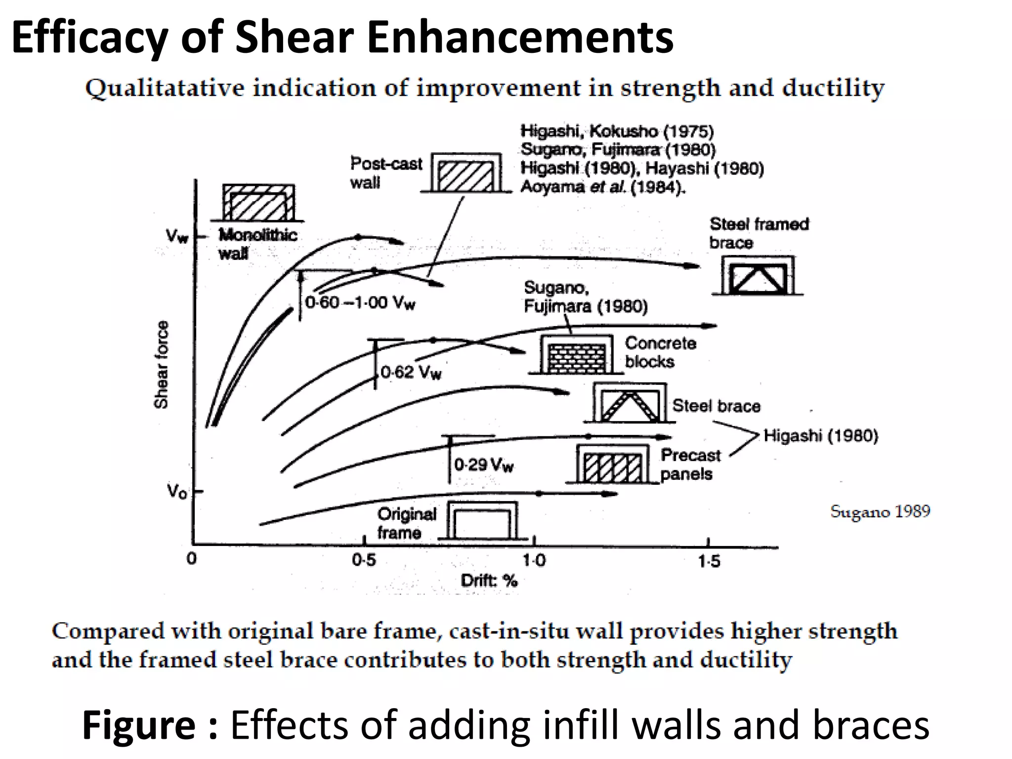
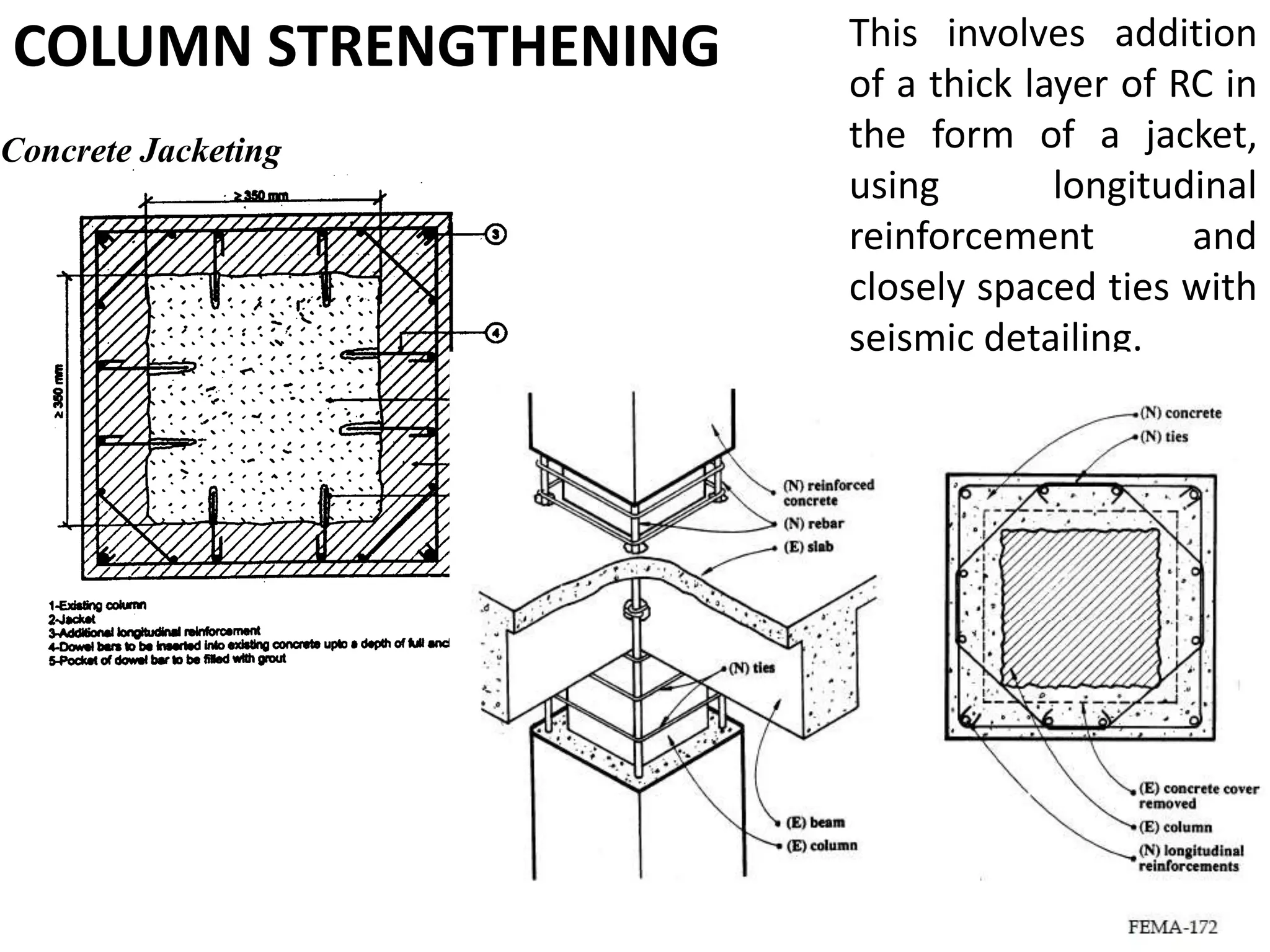
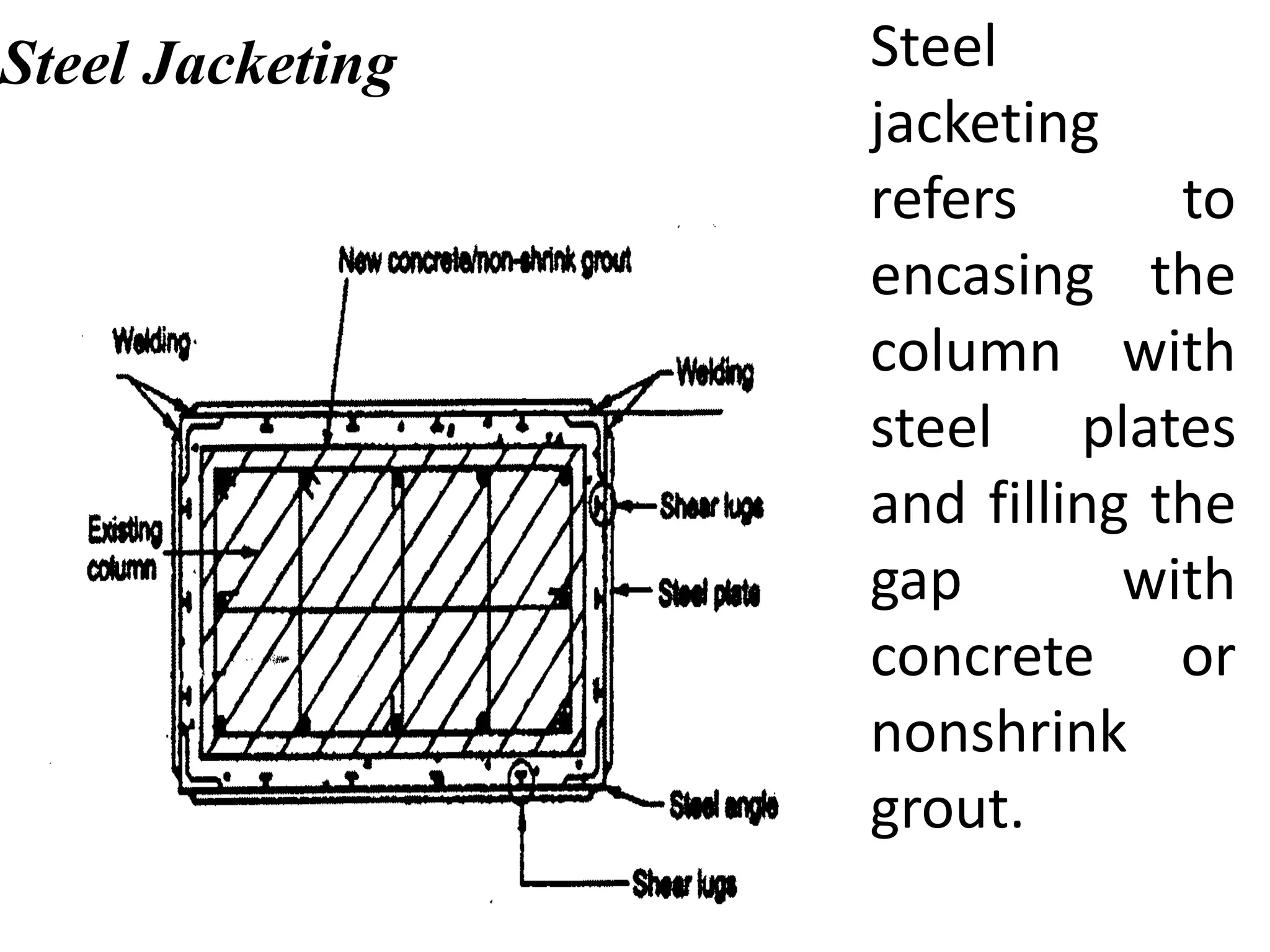
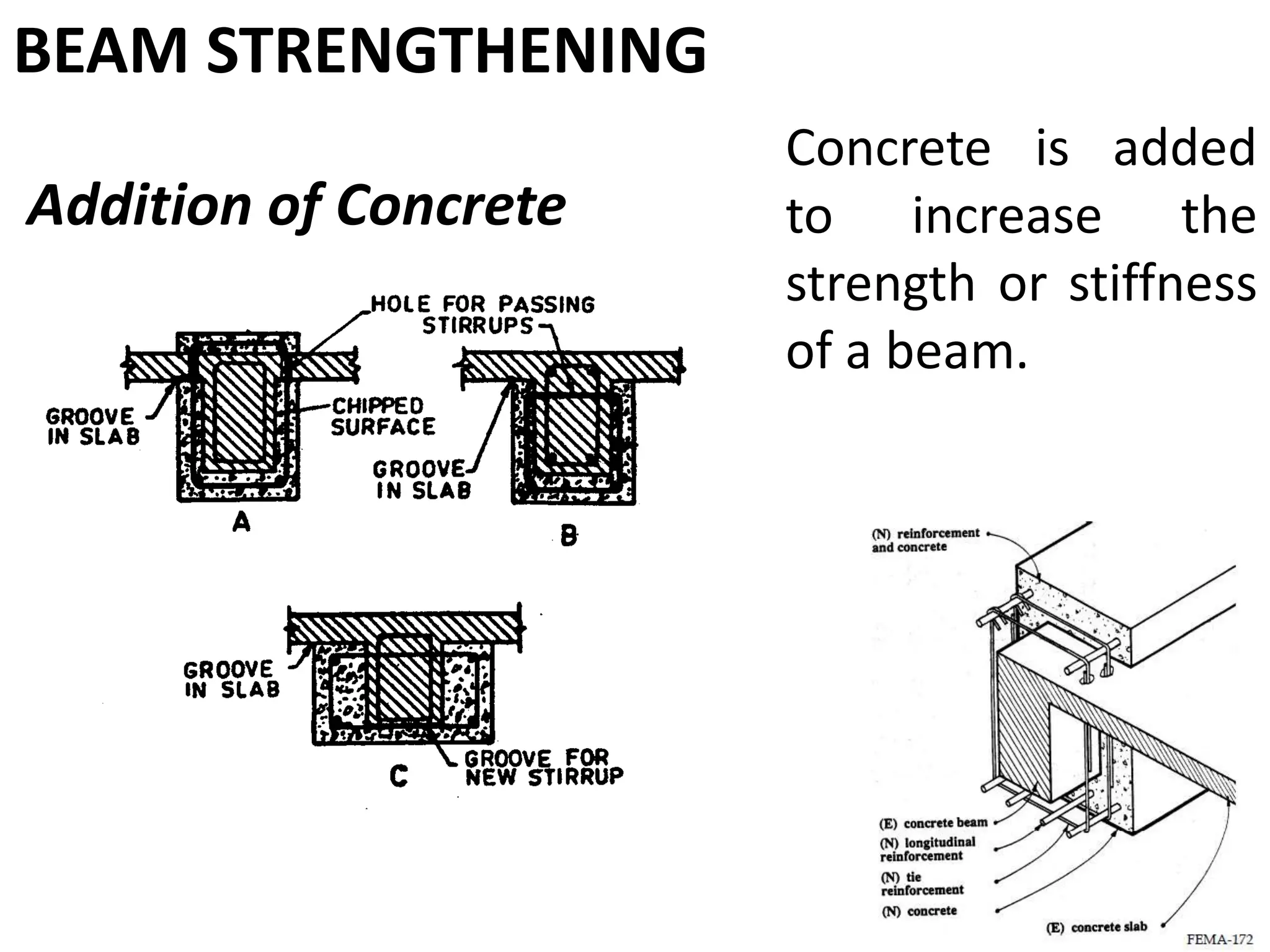
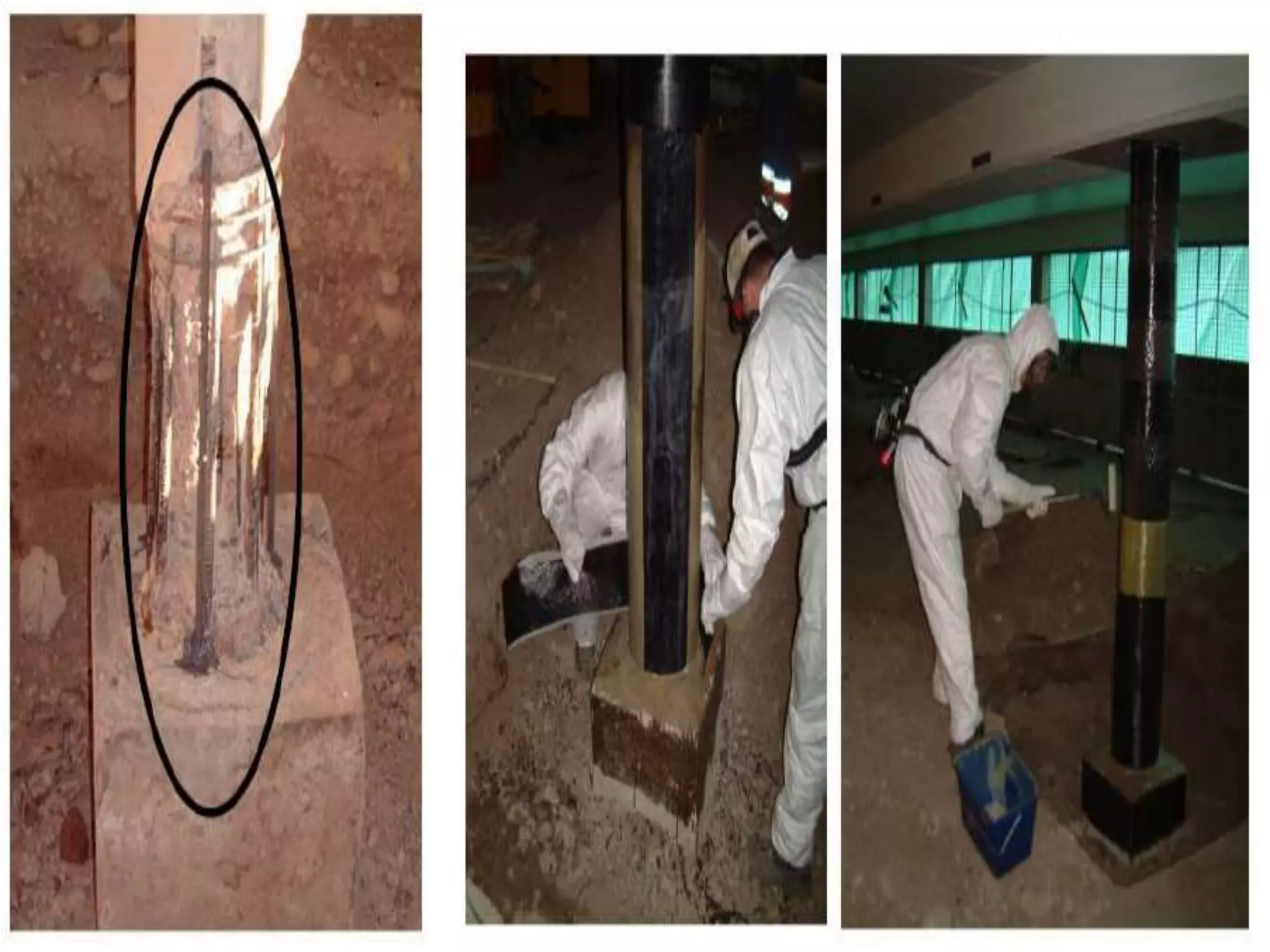
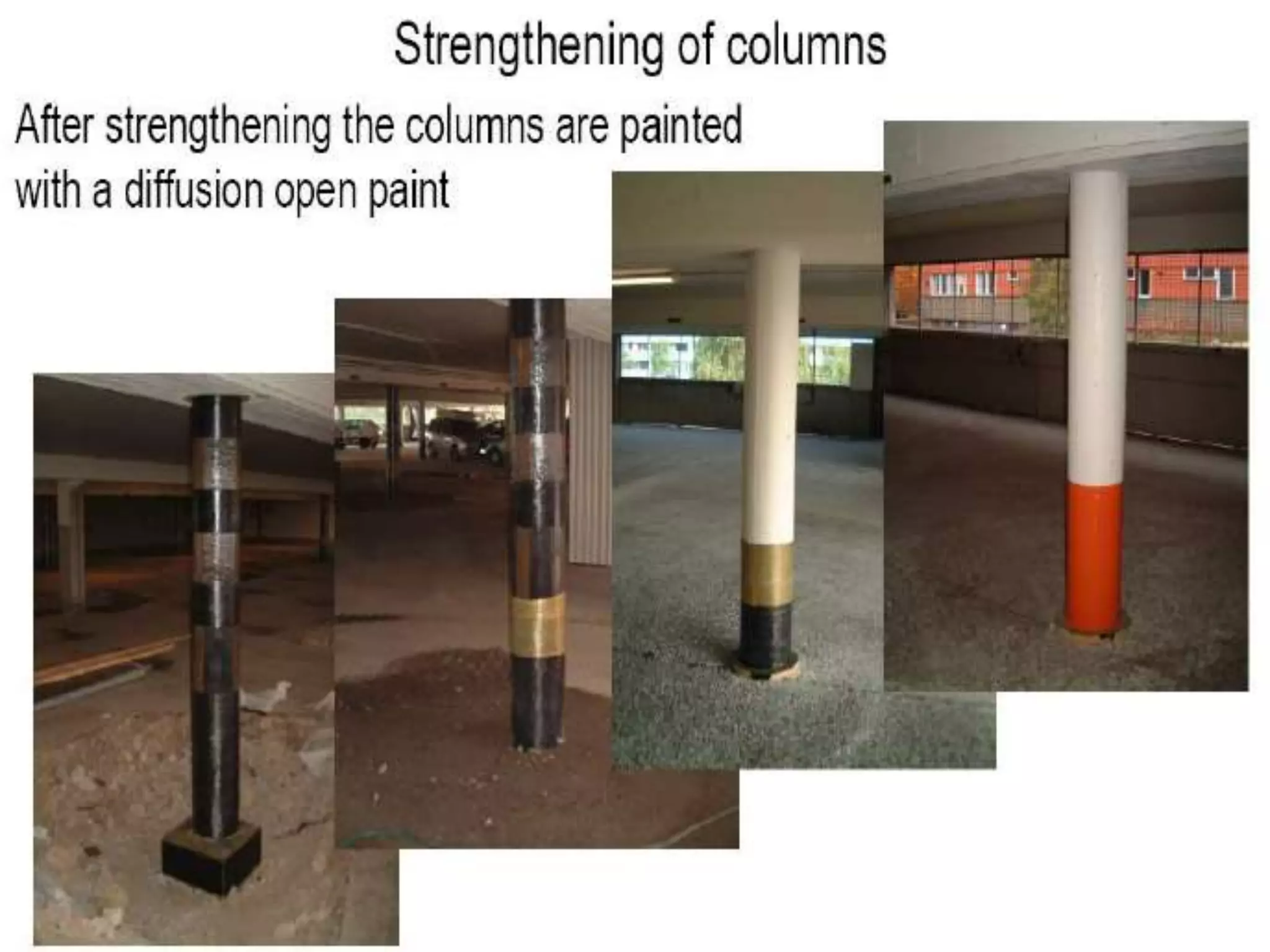
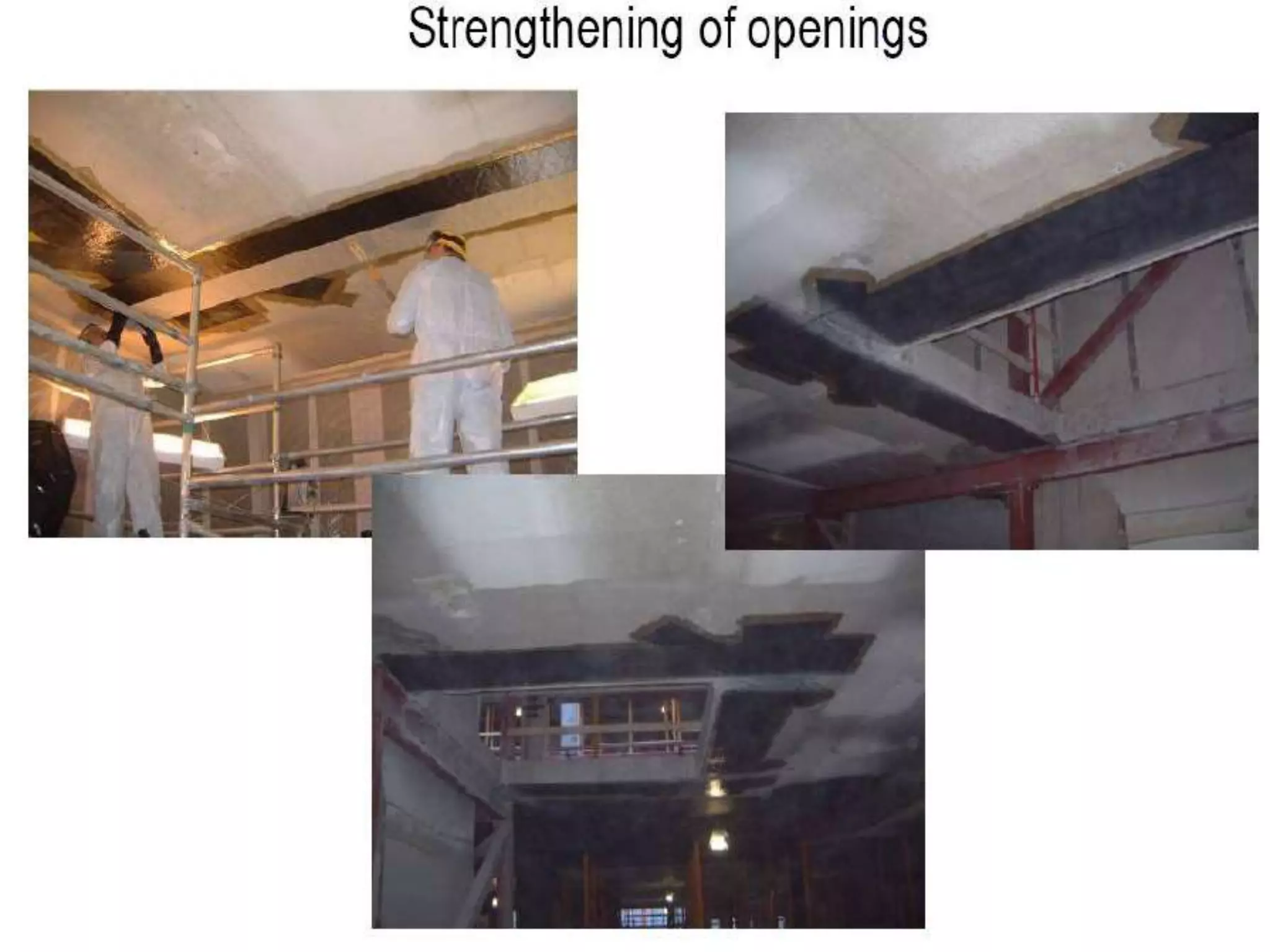
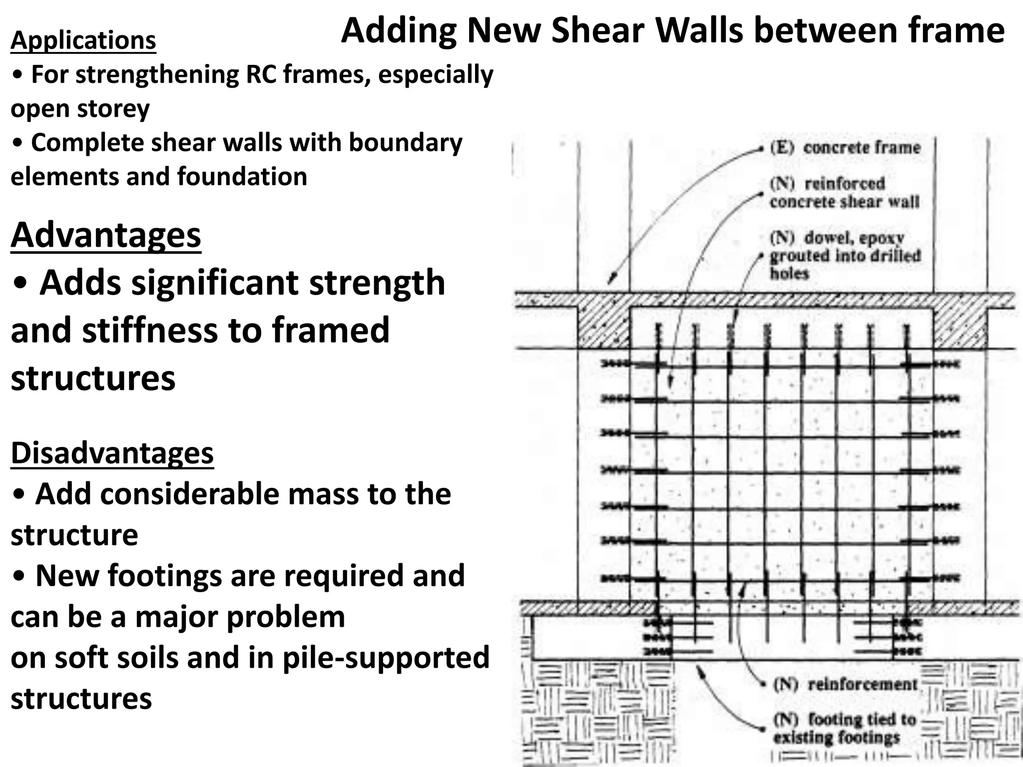
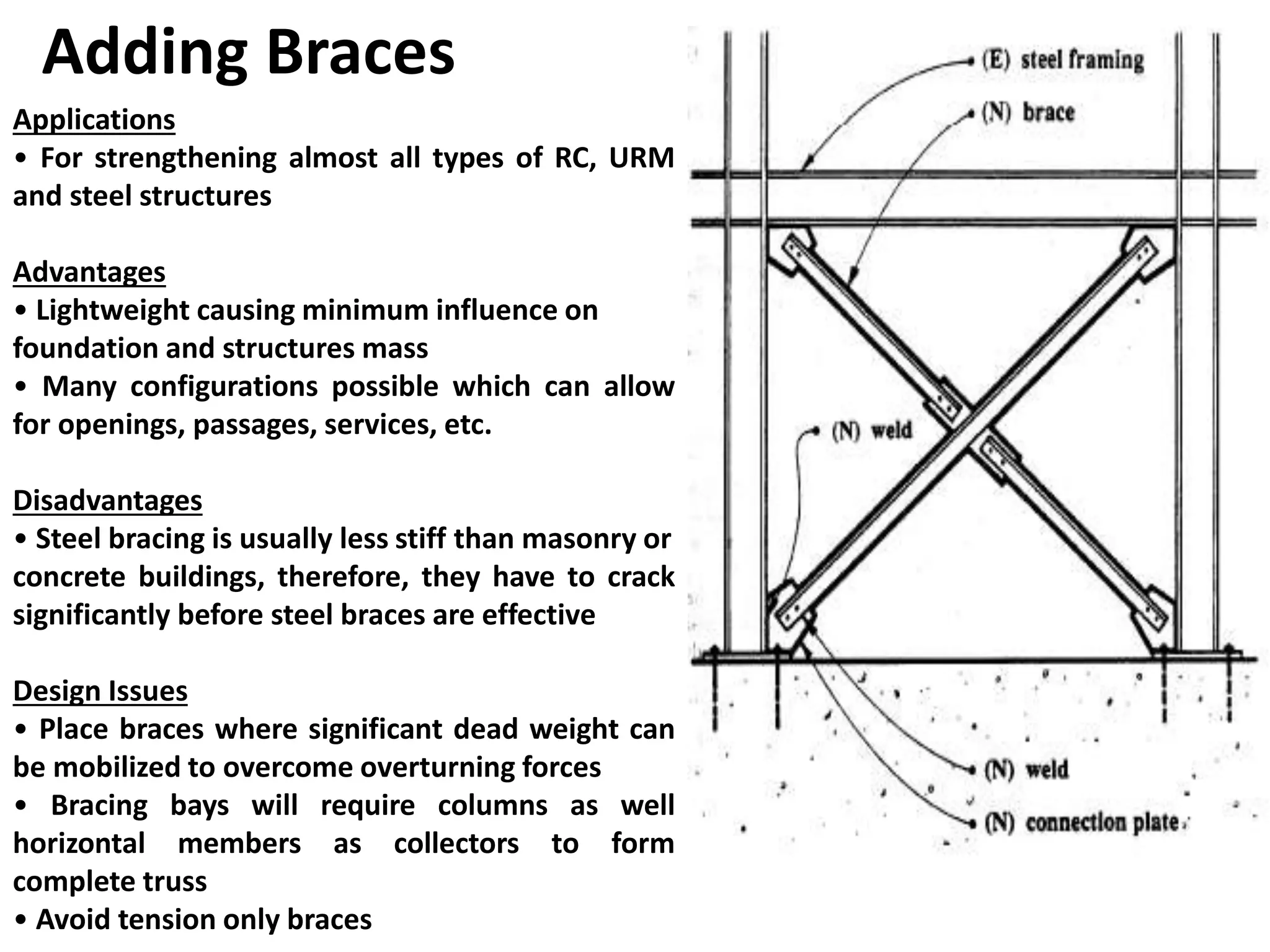
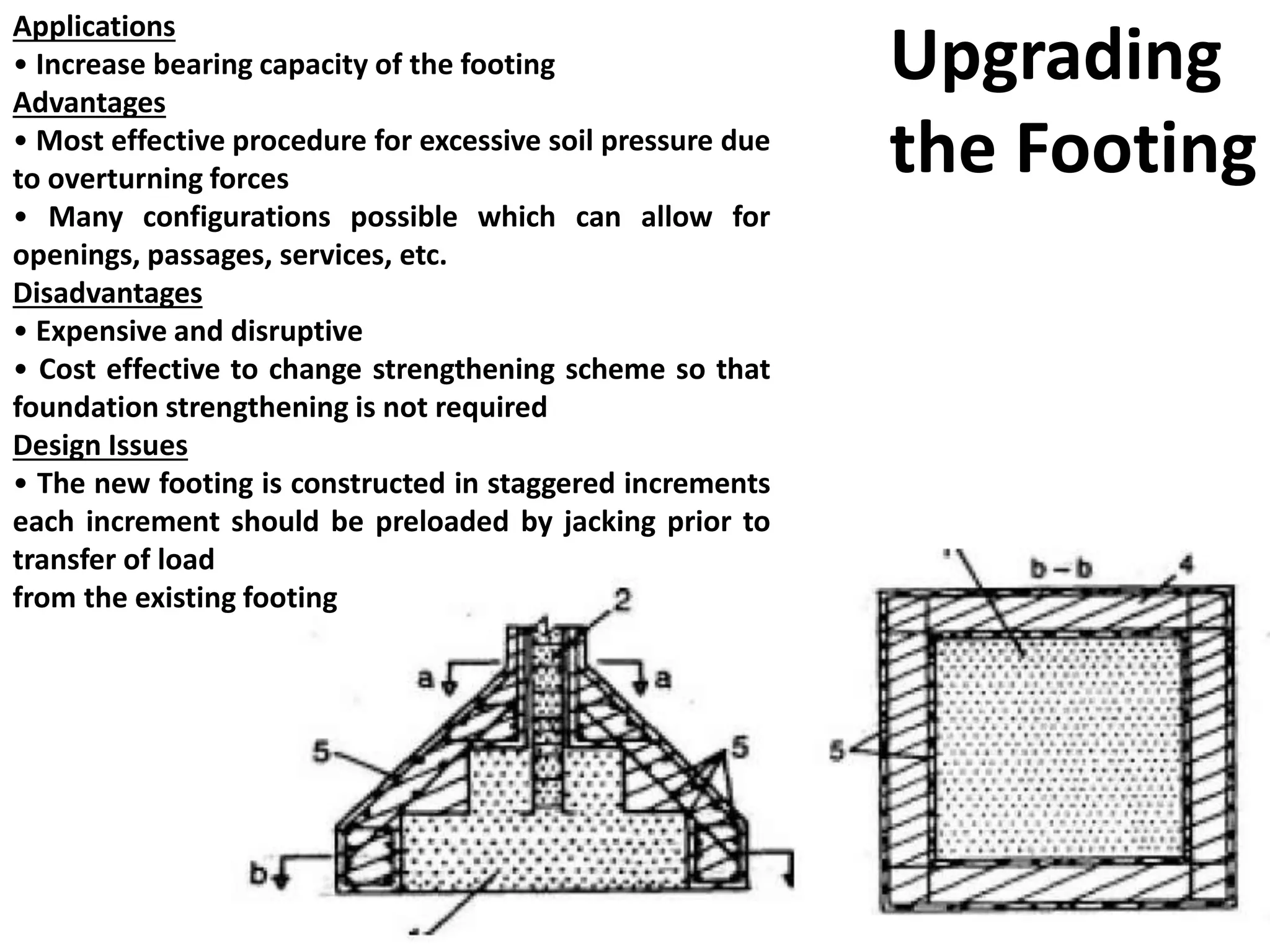
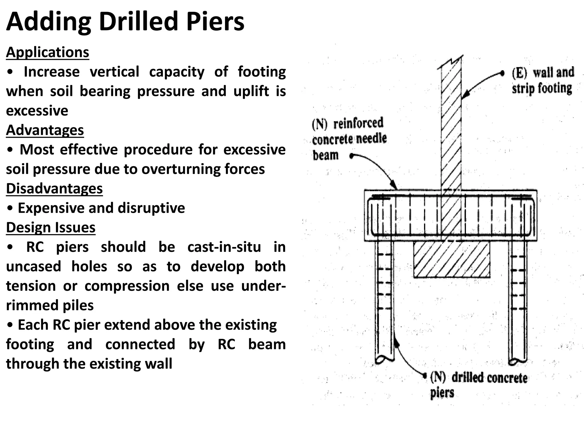
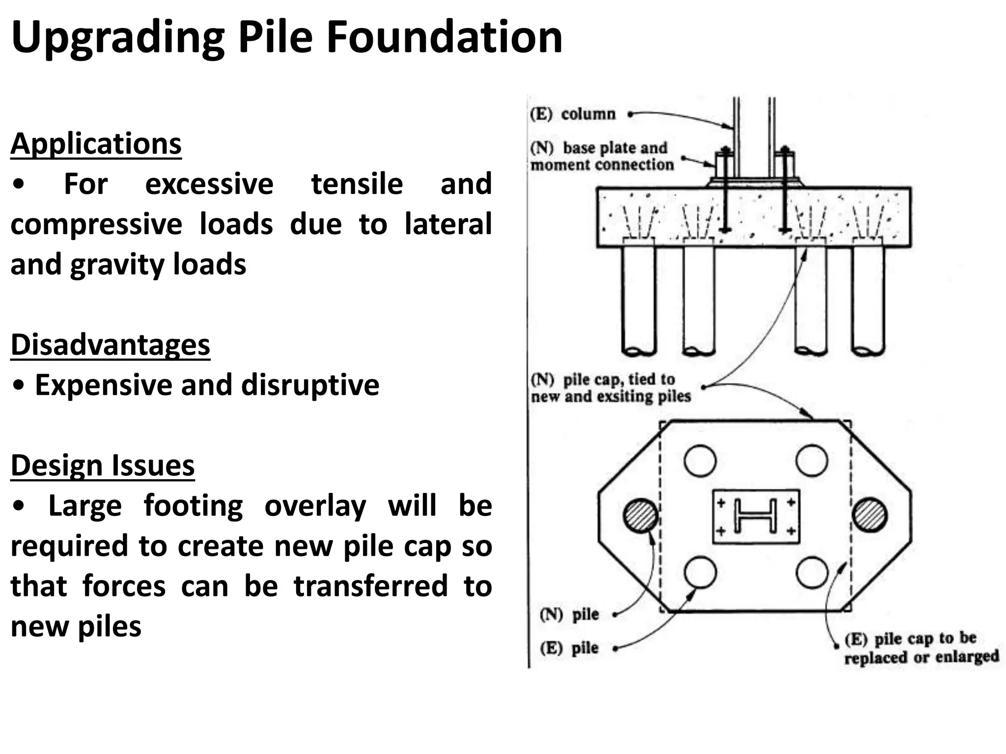
Earthquake Management, Part-2
Structural Retrofitting
Composed by
H.M.A.Mahzuz
Assistant Professor
CEE, SUST, Sylhet
What is Structural Retrofitting
• Addition of any means by which the existing
structure may be able to withstand the possible
impact of load.
• Retrofitting is applicable in beams, columns,
walls, foundation.
• It can make the structure resistant to both
vertical and horizontal loads.
• It is an innovative technique, its type, action
strategy may vary depending on site condition,
structural pattern.
OBJECTIVES OF RETROFIT
1. Increasing the strength and stiffness of the building.
2. Increasing the ductility in the lateral load versus deformation
behavior and enhancing the energy dissipation capability.
3. Giving unity to the structure.
4. Eliminating features that are sources of weakness or that
produce concentration of stresses in some members.
5. Avoiding the possibility of brittle modes of failure.
6. Enhancement of redundancy in the number of lateral load
resisting elements.
7. Elimination of the possibility of collapse.
8. The retrofit scheme should be cost effective.
9. Each retrofit strategy should consistently and reliably achieve
the intended performance objective.
Efficacy of Shear Enhancements
Figure : Effects of adding infill walls and braces
Concrete Jacketing
This involves addition
of a thick layer of RC in
the form of a jacket,
using longitudinal
reinforcement and
closely spaced ties with
seismic detailing.
COLUMN STRENGTHENING
Steel Jacketing Steel
jacketing
refers to
encasing the
column with
steel plates
and filling the
gap with
concrete or
nonshrink
grout.
BEAM STRENGTHENING
Addition of Concrete
Concrete is added
to increase the
strength or stiffness
of a beam.
Steel Plating
The technique of gluing mild steel plates to beams is often used to
improve their flexural and shear performances. It increases the strength
and stiffness of the beams and subsequently, reduces the crack width.
The addition of steel plate is simple and rapid to apply, does not reduce
the storey clear height significantly and can be applied while the
structure is in use. Glued plates of course are prone to premature
debonding which can severely limit the application of this technique.
Fiber reinforced polymer (FRP) Wrapping
Properties
Adding New Shear Walls between frameApplications
• For strengthening RC frames, especially
open storey
• Complete shear walls with boundary
elements and foundation
Advantages
• Adds significant strength
and stiffness to framed
structures
Disadvantages
• Add considerable mass to the
structure
• New footings are required and
can be a major problem
on soft soils and in pile-supported
structures
Design Guidelines
• Locate so that they align full height of the building, minimize torsion
and can be easily tied with existing frame
• Maximize the dead weight that wall can mobilize to resist
overturning uplift.
• It is economical to locate shear walls along existing framing lines in
order to provide boundary members, collectors and dead load to
help resist overturning forces.
• On the interior the shear wall continues through the slab and it
should be cast in 2 pours 48 hours apart to avoid sagging away of
concrete from the underside of the concrete slab.
• The initial pour is stopped at 450 mm from the slab soffit to allow
enough space to form shear keys and prepare the surface for next pour
up to the top of the slab.
• Functional consideration dictate the location as they break up the
interior space
Applications
• For unreinforced masonry (URM) buildings
significantly weak in in-plane shear strength
due to openings
• Most applicable for upto 5 storeyed
buildings
Advantages
• Adds significant strength and stiffness
Disadvantages
• Add considerable mass to the structure and
need
new footings between existing spread
footings
over the increased shear wall
Design Guidelines
• Fill in openings with RC or masonry
•The technique is very economical if no
foundation enhancement is required.
• Concrete overlay (shotcrete) on the entire
wall may be necessary after filling the
opening
Filling Openings
Adding Concrete to Existing Masonry
Applications
• Ideal for URM when masonry is not strong or
its in-plane shear strength is weakened by large
openings
Advantages
• Comparable stiffness to existing URM walls
• With epoxied dowels at about 600 mm each
way, shotcrete and URM will work compositely
enhancing its out-of-plane stability as well
Disadvantages
• Messy with rebound on the inside face and
transferring through floor system is difficult and
may require review of foundation details
Design Guidelines
• Provide enough shotcrete so that failure of
unreinforced section can be prevented
• Design shotcrete (thickness and einforcement)
for shear demand ignoring masonry contribution
Adding Buttresses
Applications
• For strengthening non-ductile RC and URM
structures weak in shear strength
Advantages
• Exterior work results in minimal disruption to
functional use
Disadvantages
• Need large vacant space adjacent to building
• Significantly affect the aesthetics
• Large resistance from the piles or foundation
of the buttress as it will not be able to
mobilize the dead weight
Design Issues
• A load path to transfer shear forces from the
building to buttress is required such as
collectors on the interior of the building
• Capacity required to resist overturning forces
is small for buttresses away from the building
Adding Braces
Applications
• For strengthening almost all types of RC, URM
and steel structures
Advantages
• Lightweight causing minimum influence on
foundation and structures mass
• Many configurations possible which can allow
for openings, passages, services, etc.
Disadvantages
• Steel bracing is usually less stiff than masonry or
concrete buildings, therefore, they have to crack
significantly before steel braces are effective
Design Issues
• Place braces where significant dead weight can
be mobilized to overcome overturning forces
• Bracing bays will require columns as well
horizontal members as collectors to form
complete truss
• Avoid tension only braces
Applications
• Increase bearing capacity of the footing
Advantages
• Most effective procedure for excessive soil pressure due
to overturning forces
• Many configurations possible which can allow for
openings, passages, services, etc.
Disadvantages
• Expensive and disruptive
• Cost effective to change strengthening scheme so that
foundation strengthening is not required
Design Issues
• The new footing is constructed in staggered increments
each increment should be preloaded by jacking prior to
transfer of load
from the existing footing
Upgrading
the Footing
Adding Drilled Piers
Applications
• Increase vertical capacity of footing
when soil bearing pressure and uplift is
excessive
Advantages
• Most effective procedure for excessive
soil pressure due to overturning forces
Disadvantages
• Expensive and disruptive
Design Issues
• RC piers should be cast-in-situ in
uncased holes so as to develop both
tension or compression else use under-
rimmed piles
• Each RC pier extend above the existing
footing and connected by RC beam
through the existing wall
Upgrading Pile Foundation
Applications
• For excessive tensile and
compressive loads due to lateral
and gravity loads
Disadvantages
• Expensive and disruptive
Design Issues
• Large footing overlay will be
required to create new pile cap so
that forces can be transferred to
new piles
Retrofitting a House
Thank you
Assignment
• What is your experience on Disaster
Management
Hints:
1) Discus based on your personal and
professional context
2) You can make your discussion based on any
specific disaster/ hazard.
• Maximum number of participants per topic: 02
• Presentation Style:
Multimedia presentation in a scheduled class
Submission of hard copy to the course teacher 27
At 25/01/2014 (Saturday)
Assignment will be presented by
Student ID:
»40
»41
»42
»43
»44
»45
28
At 31/01/2014 (Friday)
Assignment will be presented by
Student ID:
»46
»47
»48
»49
»50
»51
29
The persons who did not present
your assignments yet are requested
to present at the next Friday and
Saturday
AND
SO ON ………
30

Lecture earthquake-4

  • 1.
    Earthquake Management, Part-2 StructuralRetrofitting Composed by H.M.A.Mahzuz Assistant Professor CEE, SUST, Sylhet
  • 2.
    What is StructuralRetrofitting • Addition of any means by which the existing structure may be able to withstand the possible impact of load. • Retrofitting is applicable in beams, columns, walls, foundation. • It can make the structure resistant to both vertical and horizontal loads. • It is an innovative technique, its type, action strategy may vary depending on site condition, structural pattern.
  • 3.
    OBJECTIVES OF RETROFIT 1.Increasing the strength and stiffness of the building. 2. Increasing the ductility in the lateral load versus deformation behavior and enhancing the energy dissipation capability. 3. Giving unity to the structure. 4. Eliminating features that are sources of weakness or that produce concentration of stresses in some members. 5. Avoiding the possibility of brittle modes of failure. 6. Enhancement of redundancy in the number of lateral load resisting elements. 7. Elimination of the possibility of collapse. 8. The retrofit scheme should be cost effective. 9. Each retrofit strategy should consistently and reliably achieve the intended performance objective.
  • 4.
    Efficacy of ShearEnhancements Figure : Effects of adding infill walls and braces
  • 5.
    Concrete Jacketing This involvesaddition of a thick layer of RC in the form of a jacket, using longitudinal reinforcement and closely spaced ties with seismic detailing. COLUMN STRENGTHENING
  • 6.
    Steel Jacketing Steel jacketing refersto encasing the column with steel plates and filling the gap with concrete or nonshrink grout.
  • 7.
    BEAM STRENGTHENING Addition ofConcrete Concrete is added to increase the strength or stiffness of a beam.
  • 8.
    Steel Plating The techniqueof gluing mild steel plates to beams is often used to improve their flexural and shear performances. It increases the strength and stiffness of the beams and subsequently, reduces the crack width. The addition of steel plate is simple and rapid to apply, does not reduce the storey clear height significantly and can be applied while the structure is in use. Glued plates of course are prone to premature debonding which can severely limit the application of this technique.
  • 9.
    Fiber reinforced polymer(FRP) Wrapping Properties
  • 16.
    Adding New ShearWalls between frameApplications • For strengthening RC frames, especially open storey • Complete shear walls with boundary elements and foundation Advantages • Adds significant strength and stiffness to framed structures Disadvantages • Add considerable mass to the structure • New footings are required and can be a major problem on soft soils and in pile-supported structures
  • 17.
    Design Guidelines • Locateso that they align full height of the building, minimize torsion and can be easily tied with existing frame • Maximize the dead weight that wall can mobilize to resist overturning uplift. • It is economical to locate shear walls along existing framing lines in order to provide boundary members, collectors and dead load to help resist overturning forces. • On the interior the shear wall continues through the slab and it should be cast in 2 pours 48 hours apart to avoid sagging away of concrete from the underside of the concrete slab. • The initial pour is stopped at 450 mm from the slab soffit to allow enough space to form shear keys and prepare the surface for next pour up to the top of the slab. • Functional consideration dictate the location as they break up the interior space
  • 18.
    Applications • For unreinforcedmasonry (URM) buildings significantly weak in in-plane shear strength due to openings • Most applicable for upto 5 storeyed buildings Advantages • Adds significant strength and stiffness Disadvantages • Add considerable mass to the structure and need new footings between existing spread footings over the increased shear wall Design Guidelines • Fill in openings with RC or masonry •The technique is very economical if no foundation enhancement is required. • Concrete overlay (shotcrete) on the entire wall may be necessary after filling the opening Filling Openings
  • 19.
    Adding Concrete toExisting Masonry Applications • Ideal for URM when masonry is not strong or its in-plane shear strength is weakened by large openings Advantages • Comparable stiffness to existing URM walls • With epoxied dowels at about 600 mm each way, shotcrete and URM will work compositely enhancing its out-of-plane stability as well Disadvantages • Messy with rebound on the inside face and transferring through floor system is difficult and may require review of foundation details Design Guidelines • Provide enough shotcrete so that failure of unreinforced section can be prevented • Design shotcrete (thickness and einforcement) for shear demand ignoring masonry contribution
  • 20.
    Adding Buttresses Applications • Forstrengthening non-ductile RC and URM structures weak in shear strength Advantages • Exterior work results in minimal disruption to functional use Disadvantages • Need large vacant space adjacent to building • Significantly affect the aesthetics • Large resistance from the piles or foundation of the buttress as it will not be able to mobilize the dead weight Design Issues • A load path to transfer shear forces from the building to buttress is required such as collectors on the interior of the building • Capacity required to resist overturning forces is small for buttresses away from the building
  • 21.
    Adding Braces Applications • Forstrengthening almost all types of RC, URM and steel structures Advantages • Lightweight causing minimum influence on foundation and structures mass • Many configurations possible which can allow for openings, passages, services, etc. Disadvantages • Steel bracing is usually less stiff than masonry or concrete buildings, therefore, they have to crack significantly before steel braces are effective Design Issues • Place braces where significant dead weight can be mobilized to overcome overturning forces • Bracing bays will require columns as well horizontal members as collectors to form complete truss • Avoid tension only braces
  • 22.
    Applications • Increase bearingcapacity of the footing Advantages • Most effective procedure for excessive soil pressure due to overturning forces • Many configurations possible which can allow for openings, passages, services, etc. Disadvantages • Expensive and disruptive • Cost effective to change strengthening scheme so that foundation strengthening is not required Design Issues • The new footing is constructed in staggered increments each increment should be preloaded by jacking prior to transfer of load from the existing footing Upgrading the Footing
  • 23.
    Adding Drilled Piers Applications •Increase vertical capacity of footing when soil bearing pressure and uplift is excessive Advantages • Most effective procedure for excessive soil pressure due to overturning forces Disadvantages • Expensive and disruptive Design Issues • RC piers should be cast-in-situ in uncased holes so as to develop both tension or compression else use under- rimmed piles • Each RC pier extend above the existing footing and connected by RC beam through the existing wall
  • 24.
    Upgrading Pile Foundation Applications •For excessive tensile and compressive loads due to lateral and gravity loads Disadvantages • Expensive and disruptive Design Issues • Large footing overlay will be required to create new pile cap so that forces can be transferred to new piles
  • 25.
  • 26.
  • 27.
    Assignment • What isyour experience on Disaster Management Hints: 1) Discus based on your personal and professional context 2) You can make your discussion based on any specific disaster/ hazard. • Maximum number of participants per topic: 02 • Presentation Style: Multimedia presentation in a scheduled class Submission of hard copy to the course teacher 27
  • 28.
    At 25/01/2014 (Saturday) Assignmentwill be presented by Student ID: »40 »41 »42 »43 »44 »45 28
  • 29.
    At 31/01/2014 (Friday) Assignmentwill be presented by Student ID: »46 »47 »48 »49 »50 »51 29
  • 30.
    The persons whodid not present your assignments yet are requested to present at the next Friday and Saturday AND SO ON ……… 30