Strengthening of an existing reinforced concrete structure.ppt
1.
Graduation Project (1)
GraduationProject (1)
Strengthening of an existing
Strengthening of an existing
reinforced concrete structure
reinforced concrete structure
Student Name
Student Name ID No.
ID No.
Nabil Raweh Qahtan
Nabil Raweh Qahtan 980410066
980410066
Mohammed Eisa Al-Harrasi
Mohammed Eisa Al-Harrasi 980710101
980710101
Hazem Bakri Al-Naser
Hazem Bakri Al-Naser 199901443
199901443
United Arab Emirates University
College of Engineering
Civil and Environmental Department
Instructor: Dr. Ashraf Biddah
Exclusive Summary
Exclusive Summary
Themain achievements:
The main achievements:
Studying the Strengthening Methods.
Studying the Strengthening Methods.
Selection of an exiting building.
Selection of an exiting building.
Experimental Test.
Experimental Test.
Beginning of Structural Analysis.
Beginning of Structural Analysis.
4.
The general ideaof the project
The general idea of the project
The owner of a residential building wanted to
The owner of a residential building wanted to
convert his building to a commercial building.
convert his building to a commercial building.
According to change in the use of existing
According to change in the use of existing
structure, the structural system of the
structure, the structural system of the
building will be modified to fit the new
building will be modified to fit the new
changes.
changes.
PROBLEM: The old building cannot carry the
PROBLEM: The old building cannot carry the
new loads that come from the changes.
new loads that come from the changes.
DESIGN BRIEF : Design a strengthening
DESIGN BRIEF : Design a strengthening
system that can increase the capacity of the
system that can increase the capacity of the
existing structural system to be able to carry
existing structural system to be able to carry
the new loads that come from the changes
the new loads that come from the changes.
.
5.
Problems Facing Reinforced
ProblemsFacing Reinforced
Concrete Structures
Concrete Structures
Load increases.
Load increases.
Damage to structural parts.
Damage to structural parts.
Improvements in suitability for use.
Improvements in suitability for use.
Modification of structural system.
Modification of structural system.
Errors in planning or construction.
Errors in planning or construction.
6.
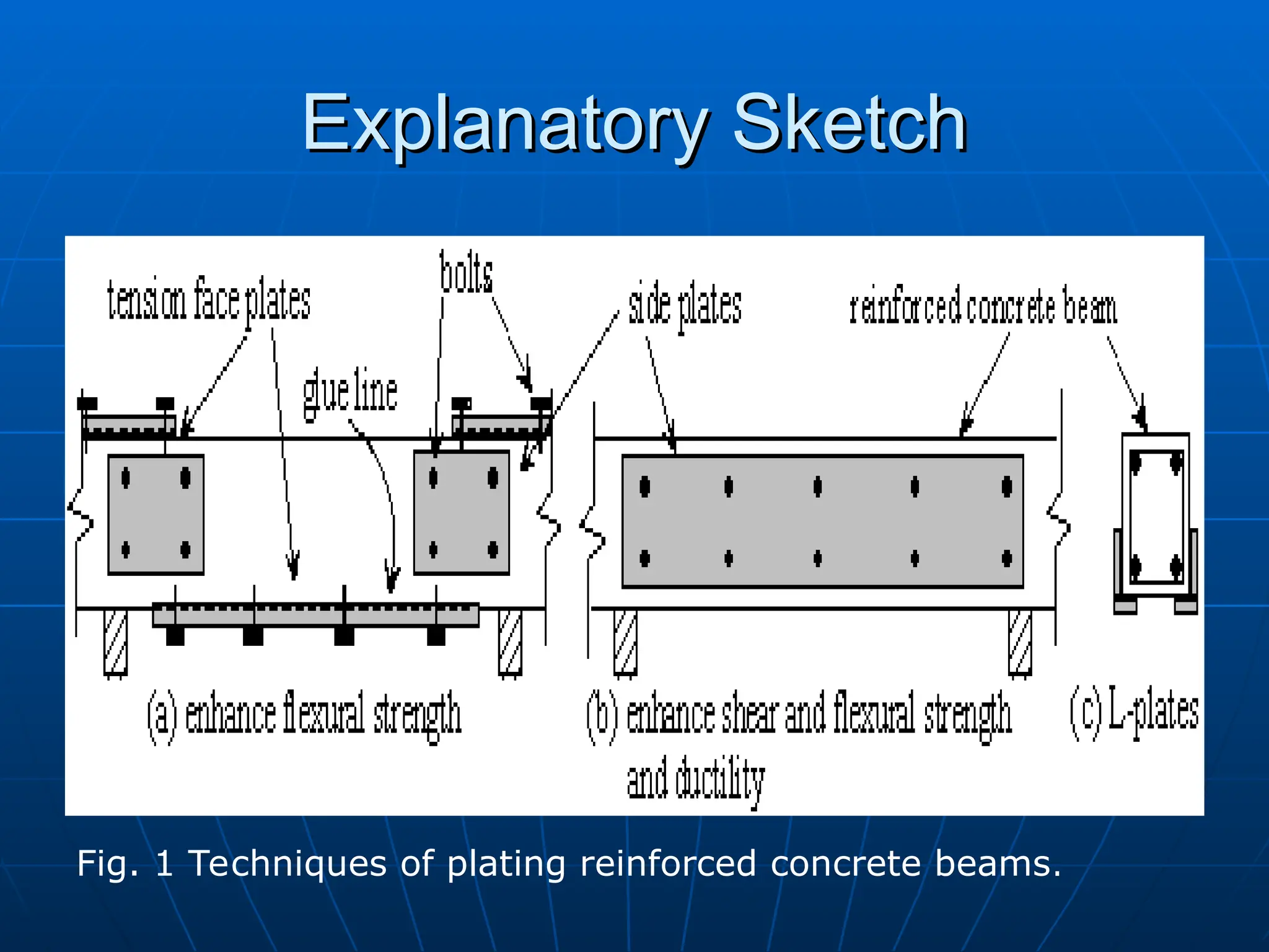
STRENGTHENING REINFORCED
STRENGTHENING REINFORCED
CONCRETESTRUCTURES BY BONDING
CONCRETE STRUCTURES BY BONDING
STEEL PLATES
STEEL PLATES
:
:
Strengthening
Strengthening is the process of
is the process of
adding capacity to a member of
adding capacity to a member of
structure.
structure.
Attachment of steel to concrete:
Attachment of steel to concrete:
1.
1. Adhesive connecting mechanism.
Adhesive connecting mechanism.
2.
2. Bolting connecting mechanism.
Bolting connecting mechanism.
STRENGTHENING REINFORCED
STRENGTHENING REINFORCED
CONCRETESTRUCTURES BY
CONCRETE STRUCTURES BY
PRESTRESSING CABLES
PRESTRESSING CABLES
:
:
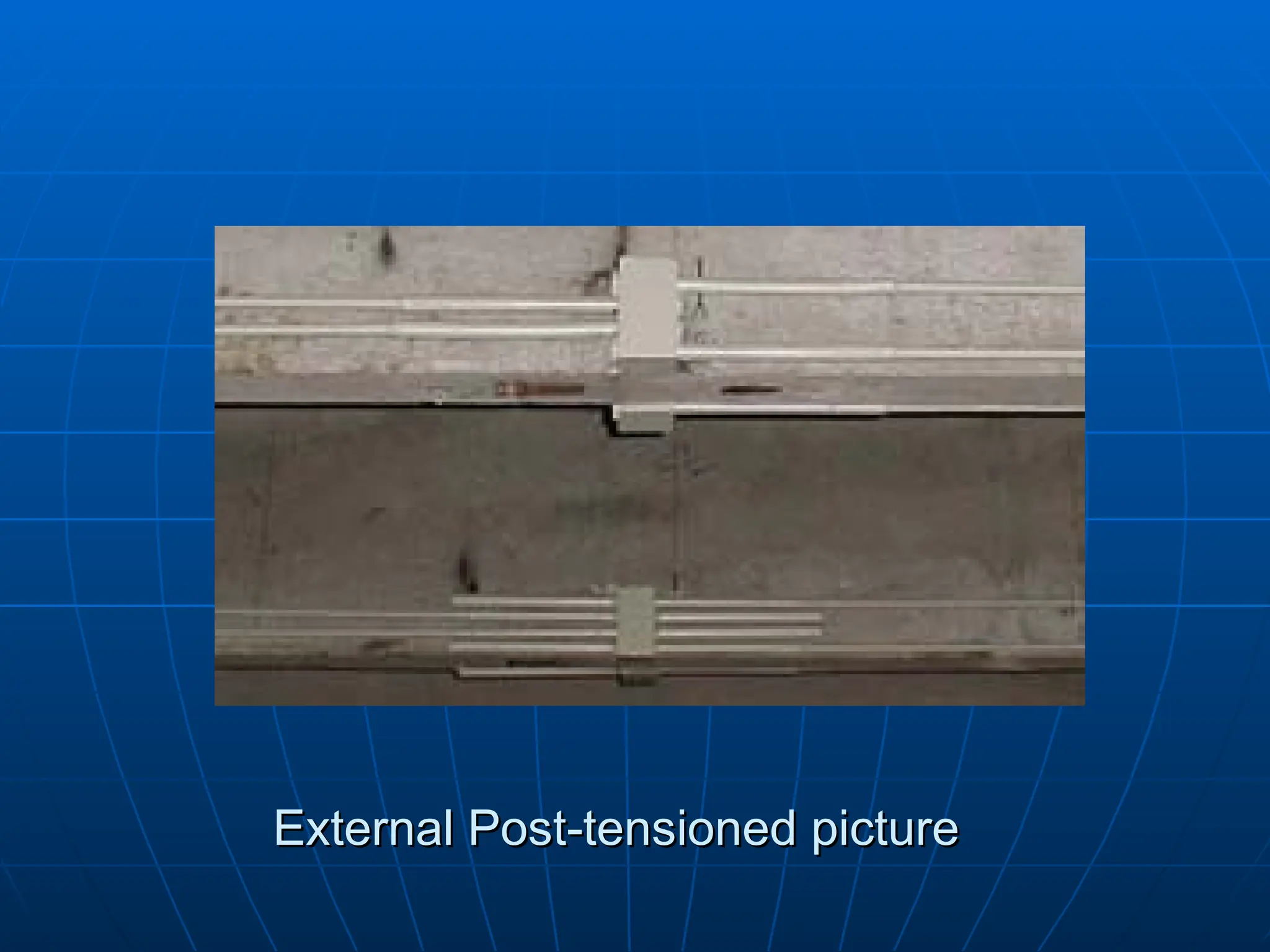
Post-tensioning
Post-tensioning is a technique used
is a technique used
to prestress reinforced concrete after
to prestress reinforced concrete after
concrete is placed.
concrete is placed.
The tensioning provides the member
The tensioning provides the member
with an immediate and active load-
with an immediate and active load-
carrying capability.
carrying capability.
The advantages ofExternal
The advantages of External
Prestressing
Prestressing
Ability to restress, destress and
Ability to restress, destress and
exchange any external prestressing
exchange any external prestressing
cable.
cable.
Crack free members.
Crack free members.
Reduce deflection.
Reduce deflection.
High fatigue and impact resistance.
High fatigue and impact resistance.
11.
The Disadvantages ofExternal
The Disadvantages of External
Prestressing
Prestressing
Usually requiring a greater section
Usually requiring a greater section
depth.
depth.
More exposed to environmental
More exposed to environmental
influences (fire, vandalism,
influences (fire, vandalism,
aggressive chemicals etc.).
aggressive chemicals etc.).
Handling of the tensioning devices
Handling of the tensioning devices
may be more difficult.
may be more difficult.
High cost.
High cost.
Concrete Jackets
Concrete Jackets
(SectionEnlargement)
(Section Enlargement)
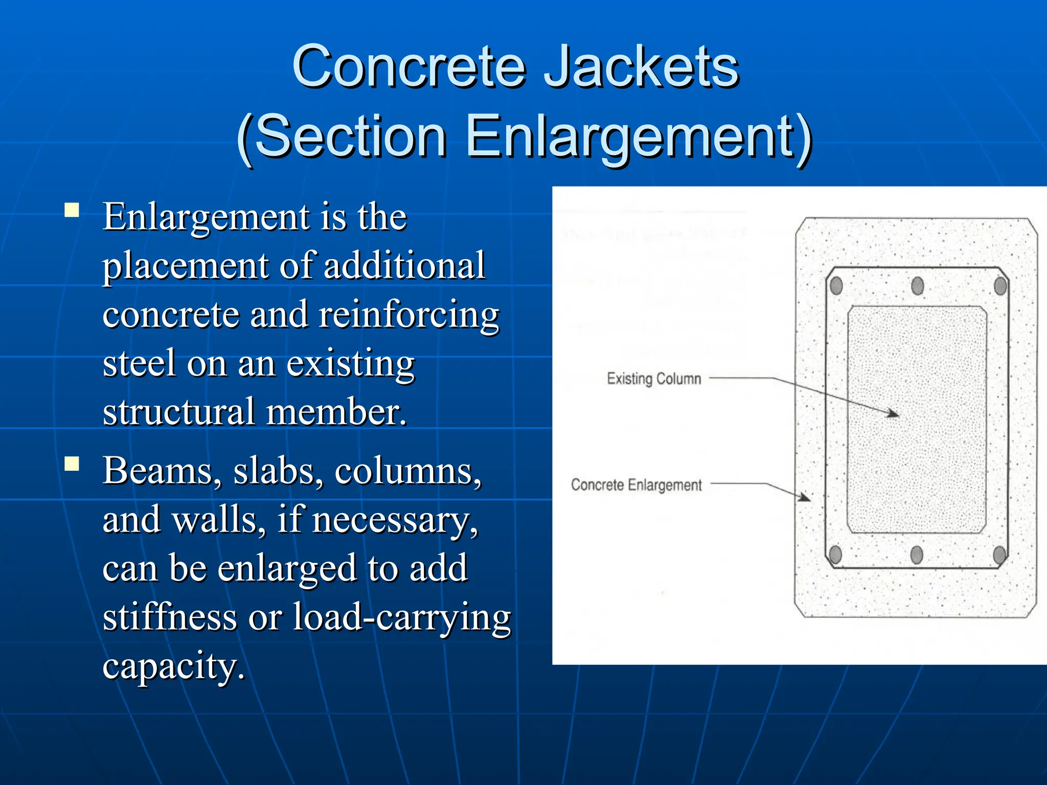
Enlargement is the
Enlargement is the
placement of additional
placement of additional
concrete and reinforcing
concrete and reinforcing
steel on an existing
steel on an existing
structural member.
structural member.
Beams, slabs, columns,
Beams, slabs, columns,
and walls, if necessary,
and walls, if necessary,
can be enlarged to add
can be enlarged to add
stiffness or load-carrying
stiffness or load-carrying
capacity.
capacity.
14.
Concrete Jackets
Concrete Jackets
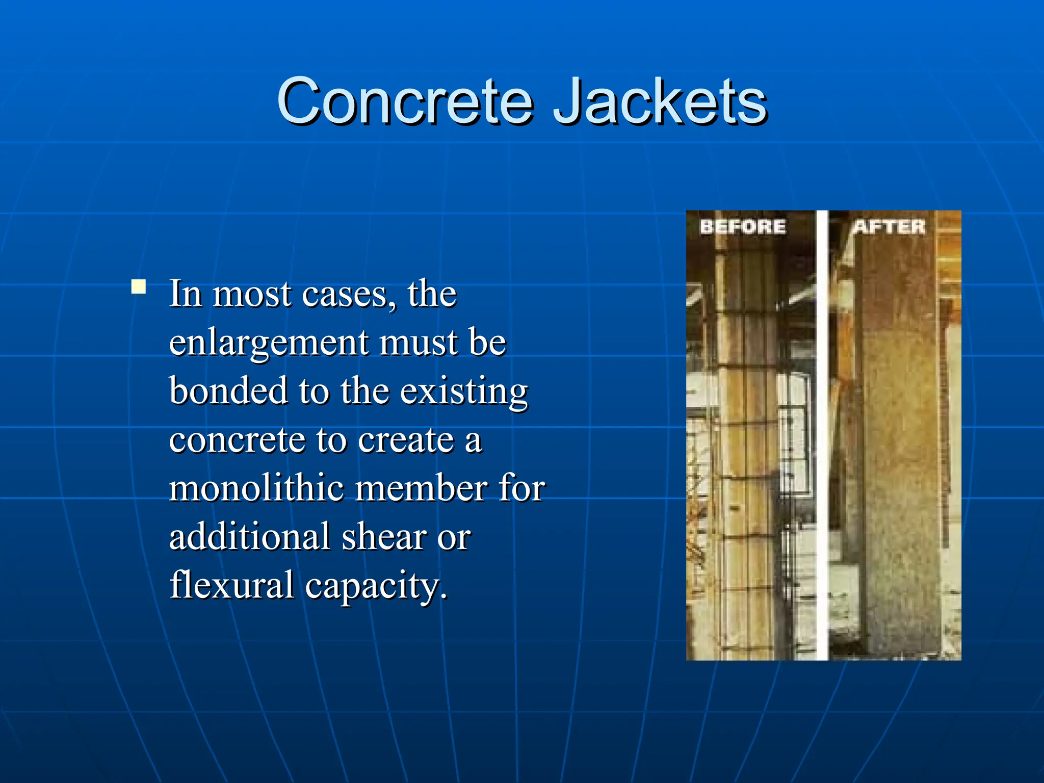
In most cases, the
In most cases, the
enlargement must be
enlargement must be
bonded to the existing
bonded to the existing
concrete to create a
concrete to create a
monolithic member for
monolithic member for
additional shear or
additional shear or
flexural capacity.
flexural capacity.
15.
Column Compressive strengtheningby
Column Compressive strengthening by
Section Enlargement
Section Enlargement
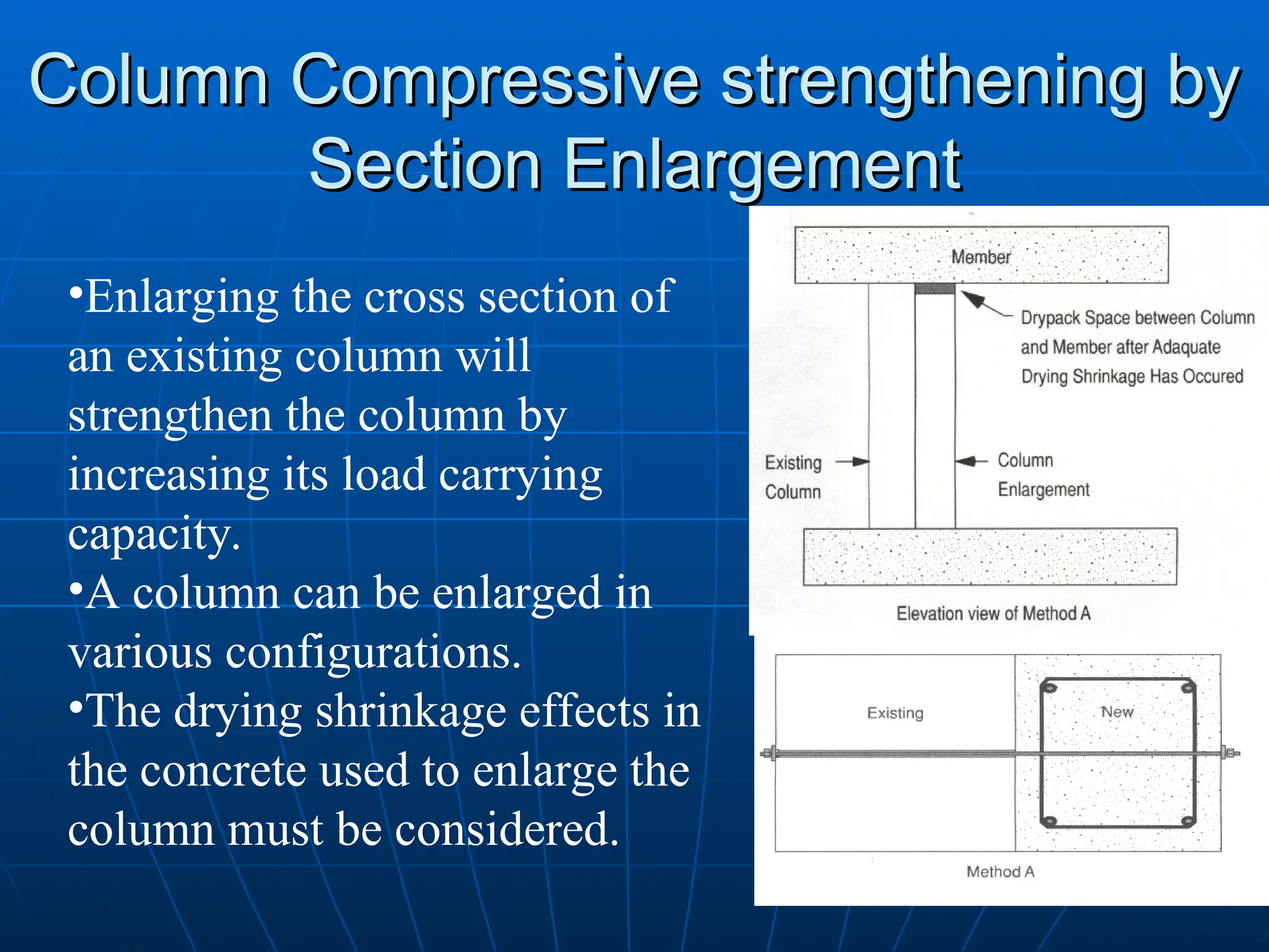
•Enlarging the cross section of
an existing column will
strengthen the column by
increasing its load carrying
capacity.
•A column can be enlarged in
various configurations.
•The drying shrinkage effects in
the concrete used to enlarge the
column must be considered.
16.
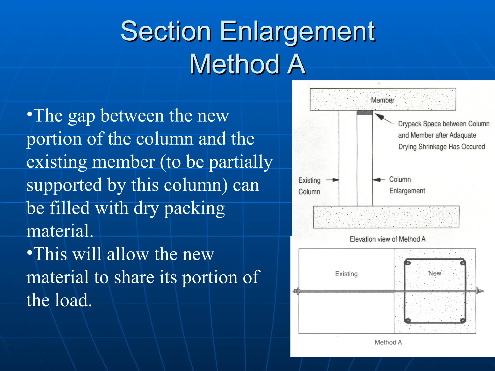
Section Enlargement
Section Enlargement
MethodA
Method A
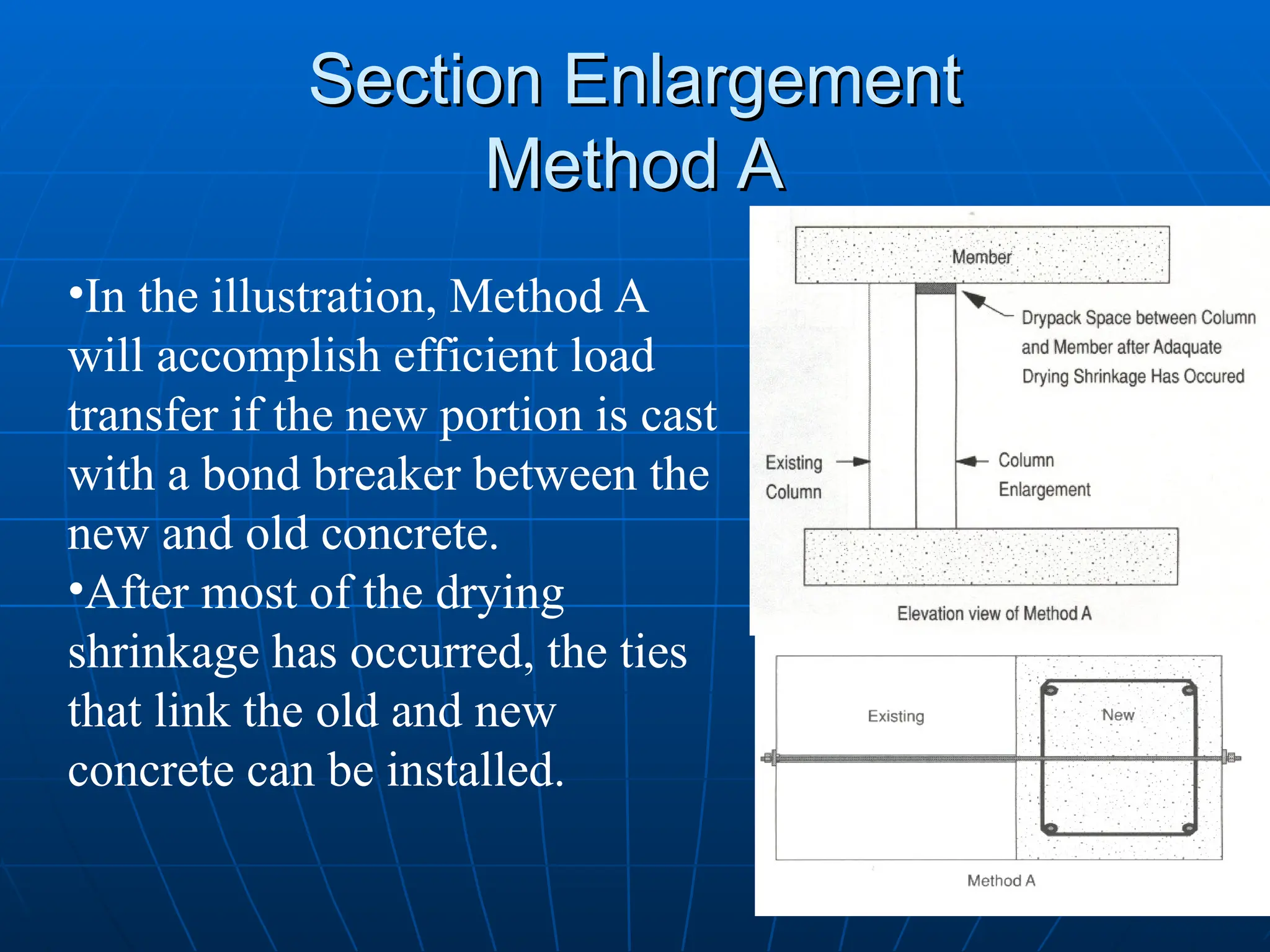
•In the illustration, Method A
will accomplish efficient load
transfer if the new portion is cast
with a bond breaker between the
new and old concrete.
•After most of the drying
shrinkage has occurred, the ties
that link the old and new
concrete can be installed.
17.
Section Enlargement
Section Enlargement
MethodA
Method A
•The gap between the new
portion of the column and the
existing member (to be partially
supported by this column) can
be filled with dry packing
material.
•This will allow the new
material to share its portion of
the load.
18.
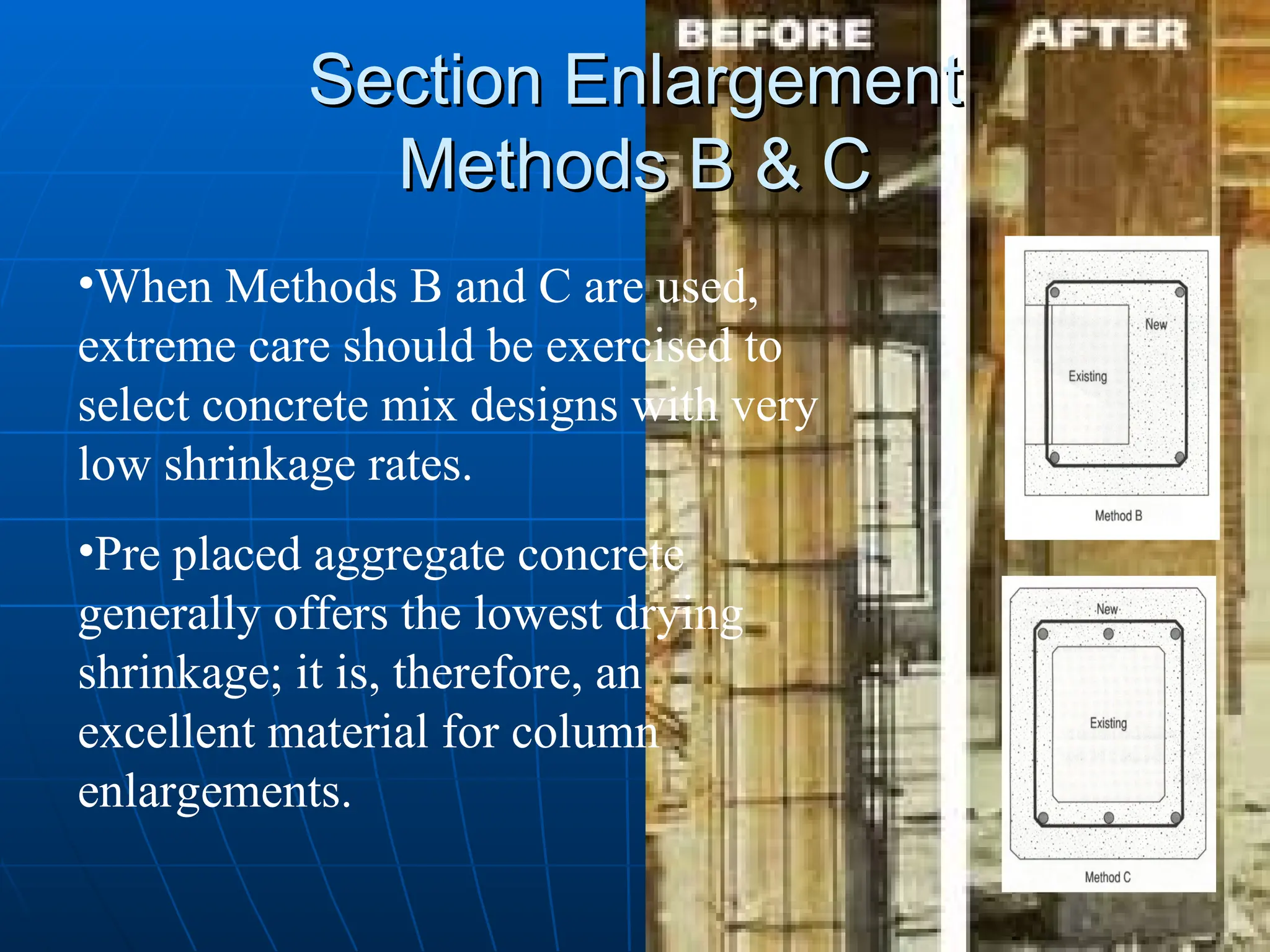
Section Enlargement
Section Enlargement
MethodsB & C
Methods B & C
•When Methods B and C are used,
extreme care should be exercised to
select concrete mix designs with very
low shrinkage rates.
•Pre placed aggregate concrete
generally offers the lowest drying
shrinkage; it is, therefore, an
excellent material for column
enlargements.
19.
Disadvantages of theconcrete
Disadvantages of the concrete
jackets
jackets
Increasing the size of the element, which make
Increasing the size of the element, which make
its usage very limited.
its usage very limited.
Difficult to construct in some active buildings
Difficult to construct in some active buildings
such as hospitals, schools because of the noise
such as hospitals, schools because of the noise
of equipments.
of equipments.
Needs shuttering, formworks, reinforced steel,
Needs shuttering, formworks, reinforced steel,
concrete, concrete pumps, vibrators, …etc.
concrete, concrete pumps, vibrators, …etc.
Fiber Reinforced Polymer(FRP)
Fiber Reinforced Polymer (FRP)
FRP is a new class of composite
FRP is a new class of composite
material for the development and
material for the development and
repair of new and deteriorating
repair of new and deteriorating
structures in Civil Engineering.
structures in Civil Engineering.
Search for alternatives to Steel and
Search for alternatives to Steel and
alloys to combat the high costs of
alloys to combat the high costs of
repair and maintenance of structures
repair and maintenance of structures
damaged by corrosion and heavy use.
damaged by corrosion and heavy use.
22.
FRP Laminate Structure
FRPLaminate Structure
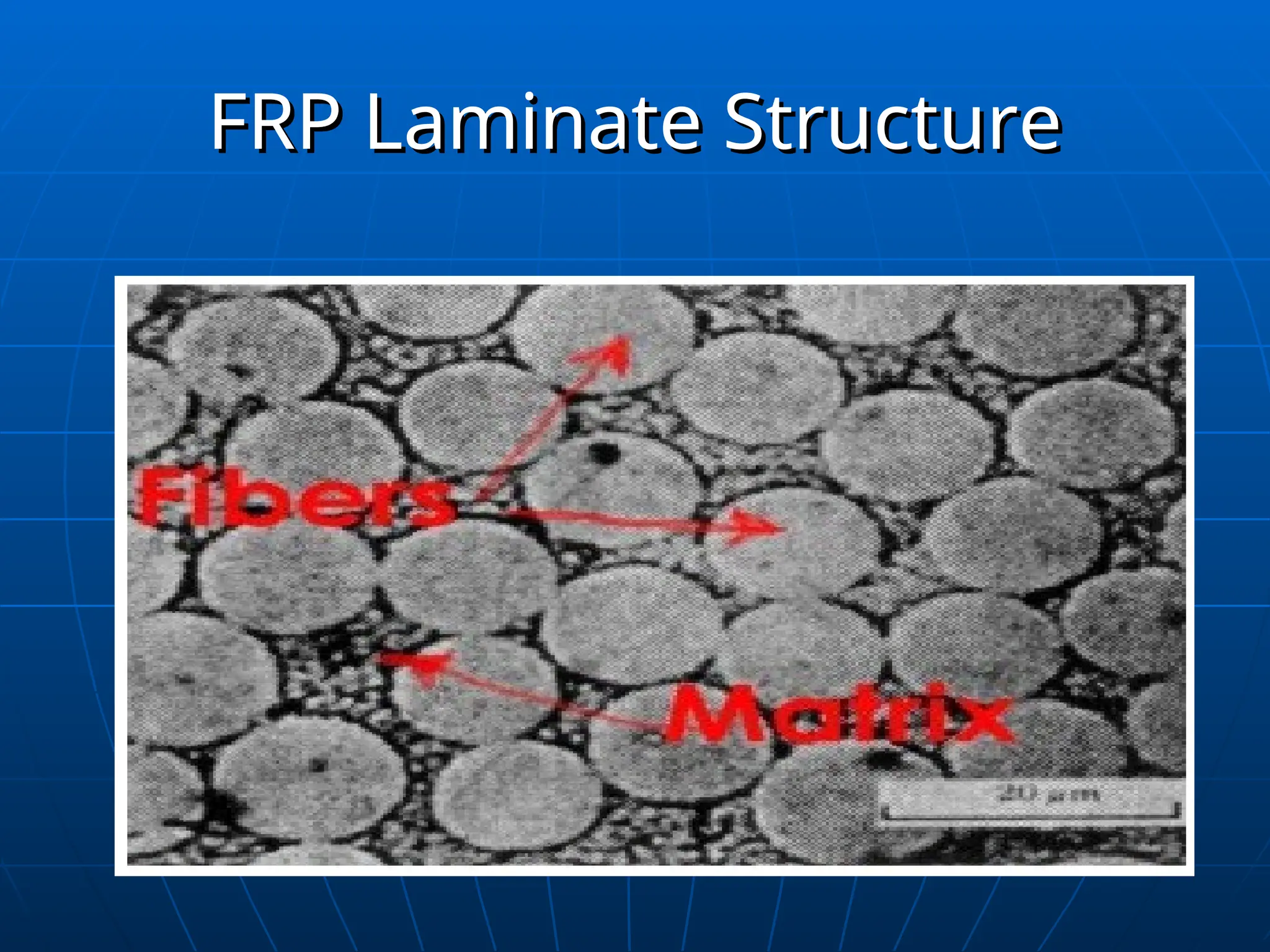
• FRPs are organized in a laminate
FRPs are organized in a laminate
structure.
structure.
• each lamina (flat layer) contains an
each lamina (flat layer) contains an
arrangement of unidirectional fibers
arrangement of unidirectional fibers
fabrics embedded within a thin layer
fabrics embedded within a thin layer
of light polymer matrix material.
of light polymer matrix material.
FRP consists of two main components:
FRP consists of two main components:
1.
1.Fibers.
Fibers.
2.
2.Resin or Matrix.
Resin or Matrix.
Types of FRP
Typesof FRP
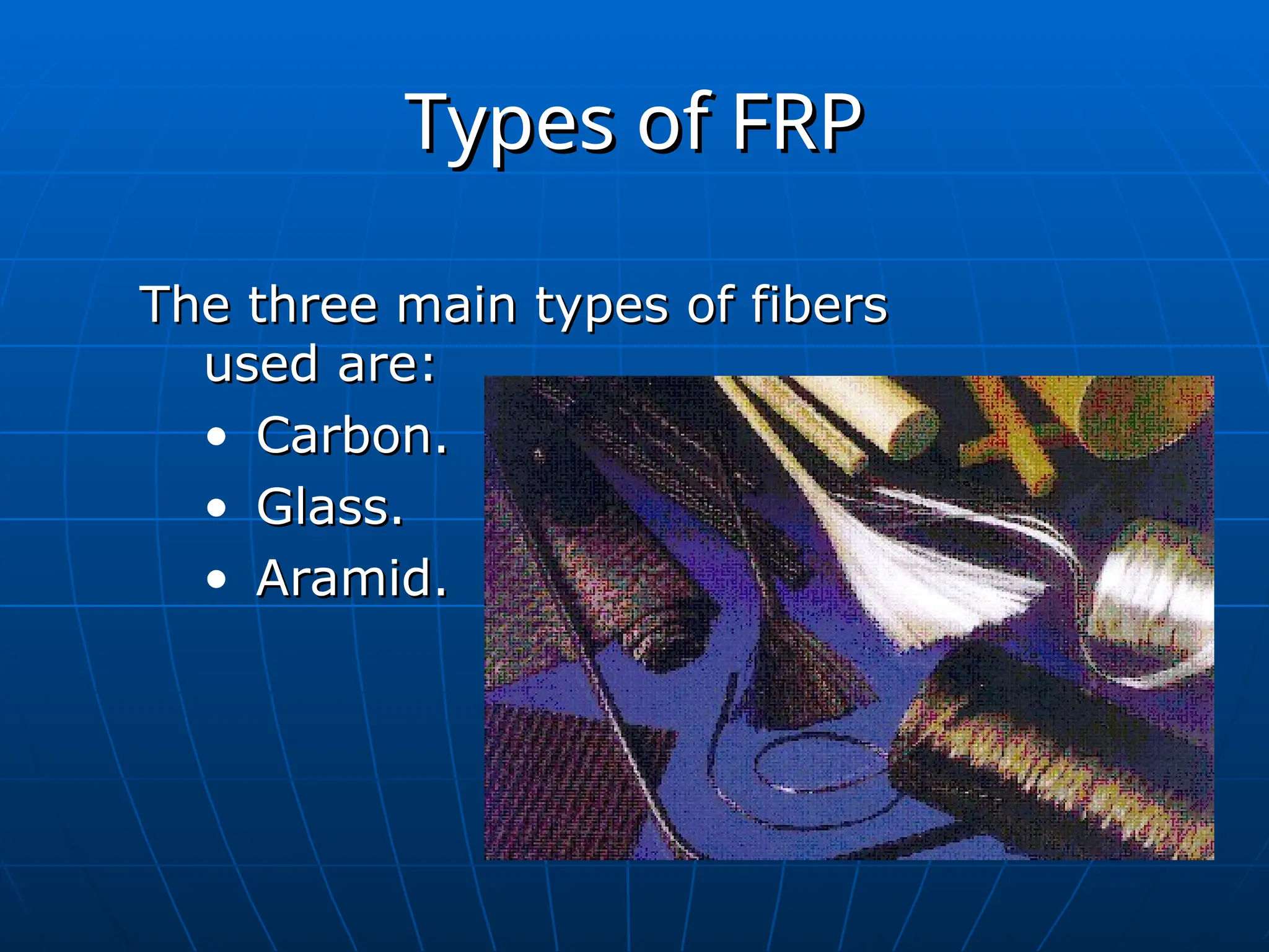
The three main types of fibers
The three main types of fibers
used are:
used are:
• Carbon.
Carbon.
• Glass.
Glass.
• Aramid.
Aramid.
25.
Suitability of FRPfor Uses in
Suitability of FRP for Uses in
Structural Engineering
Structural Engineering
FRP properties and advantages makes it
FRP properties and advantages makes it
ideal for wide spread applications in
ideal for wide spread applications in
construction worldwide.
construction worldwide.
FRP has a few disadvantages.
FRP has a few disadvantages.
26.
Advantages of FRP
Advantagesof FRP
:
:
Corrosion Resistance.
Corrosion Resistance.
Lightweight.
Lightweight.
Ease of installation.
Ease of installation.
Less Finishing.
Less Finishing.
Less maintenance.
Less maintenance.
Ductility of FRP wrapped members
Ductility of FRP wrapped members
improves dramatically.
improves dramatically.
They are ideal for external application.
They are ideal for external application.
27.
Advantages of FRP
Advantagesof FRP
They are extremely durable.
They are extremely durable.
They are available in various
They are available in various
forms: sheets, plates, fabric, etc.
forms: sheets, plates, fabric, etc.
They are available in long lengths
They are available in long lengths
that eliminates joints and splices.
that eliminates joints and splices.
They cure within 24 hours.
They cure within 24 hours.
Versatility.
Versatility.
Anti-seismic behavior.
Anti-seismic behavior.
28.
Disadvantages of FRP
Disadvantagesof FRP
High cost, susceptibility to
High cost, susceptibility to
deformation under long-term loads
deformation under long-term loads
Temperature and moisture effects,
Temperature and moisture effects,
lack of design codes, and most
lack of design codes, and most
importantly, lack of awareness.
importantly, lack of awareness.
29.
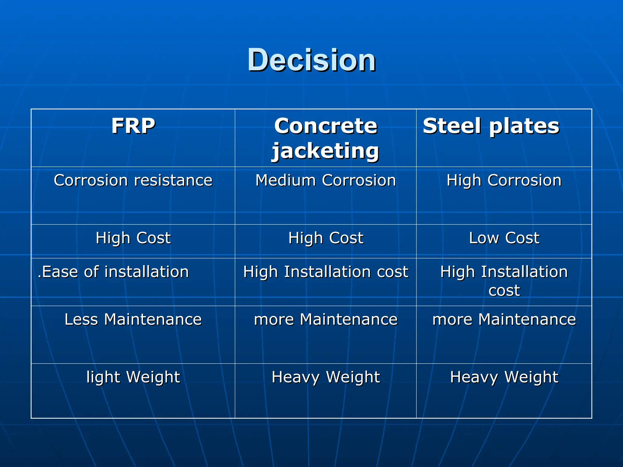
Decision
Decision
Steel plates
Steel plates
Concrete
Concrete
jacketing
jacketing
FRP
FRP
HighCorrosion
High Corrosion
Medium Corrosion
Medium Corrosion
Corrosion resistance
Corrosion resistance
Low Cost
Low Cost
High Cost
High Cost
High Cost
High Cost
High Installation
High Installation
cost
cost
High Installation cost
High Installation cost
Ease of installation
Ease of installation
.
.
more Maintenance
more Maintenance
more Maintenance
more Maintenance
Less Maintenance
Less Maintenance
Heavy Weight
Heavy Weight
Heavy Weight
Heavy Weight
light Weight
light Weight
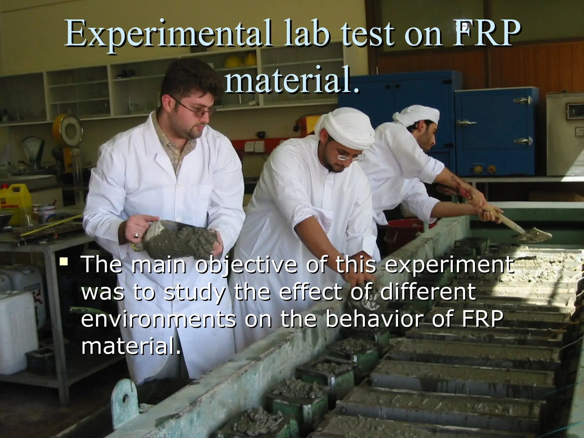
Experimental lab teston FRP
Experimental lab test on FRP
material.
material.
The main objective of this experiment
The main objective of this experiment
was to study the effect of different
was to study the effect of different
environments on the behavior of FRP
environments on the behavior of FRP
material.
material.
34.
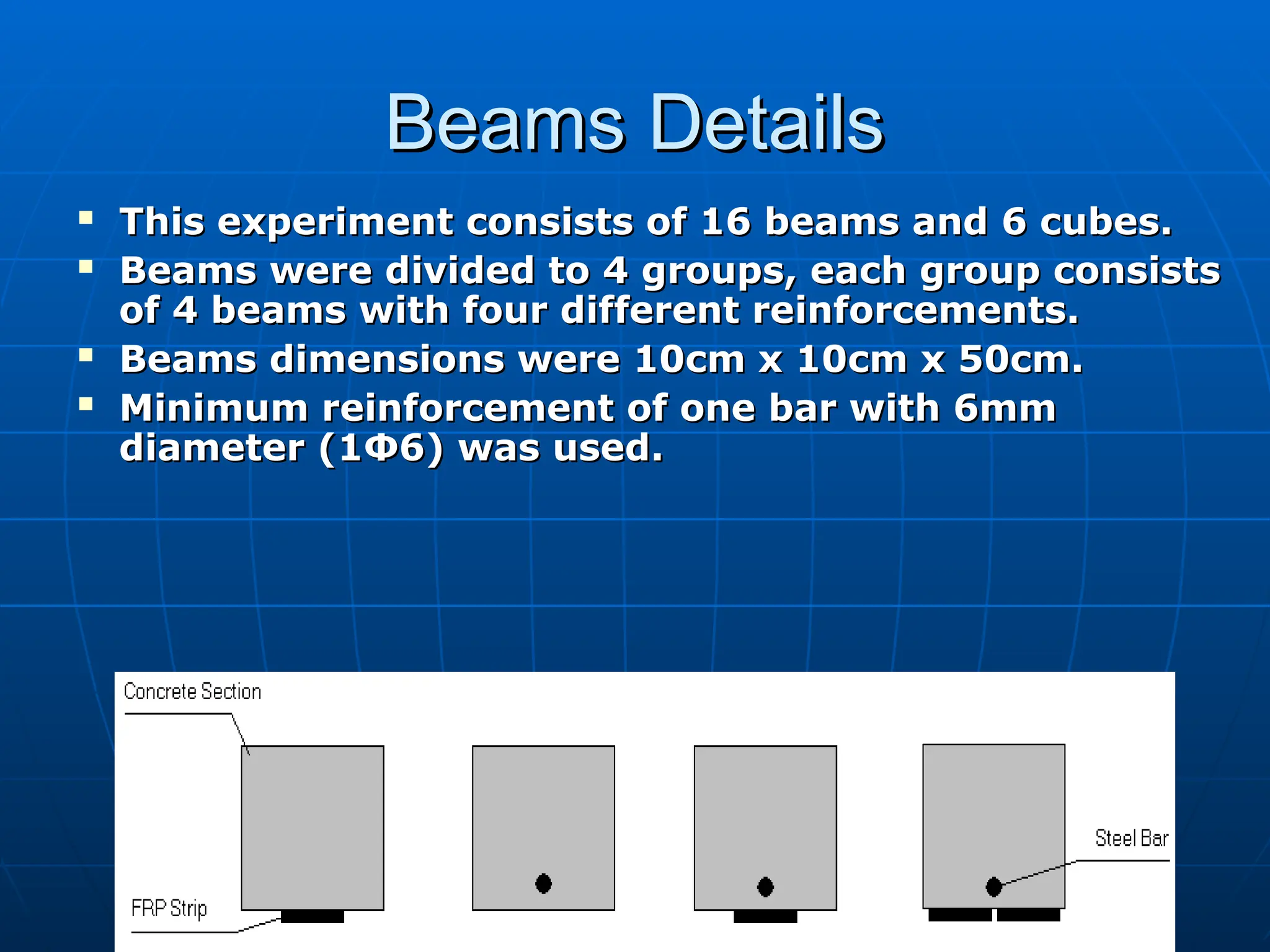
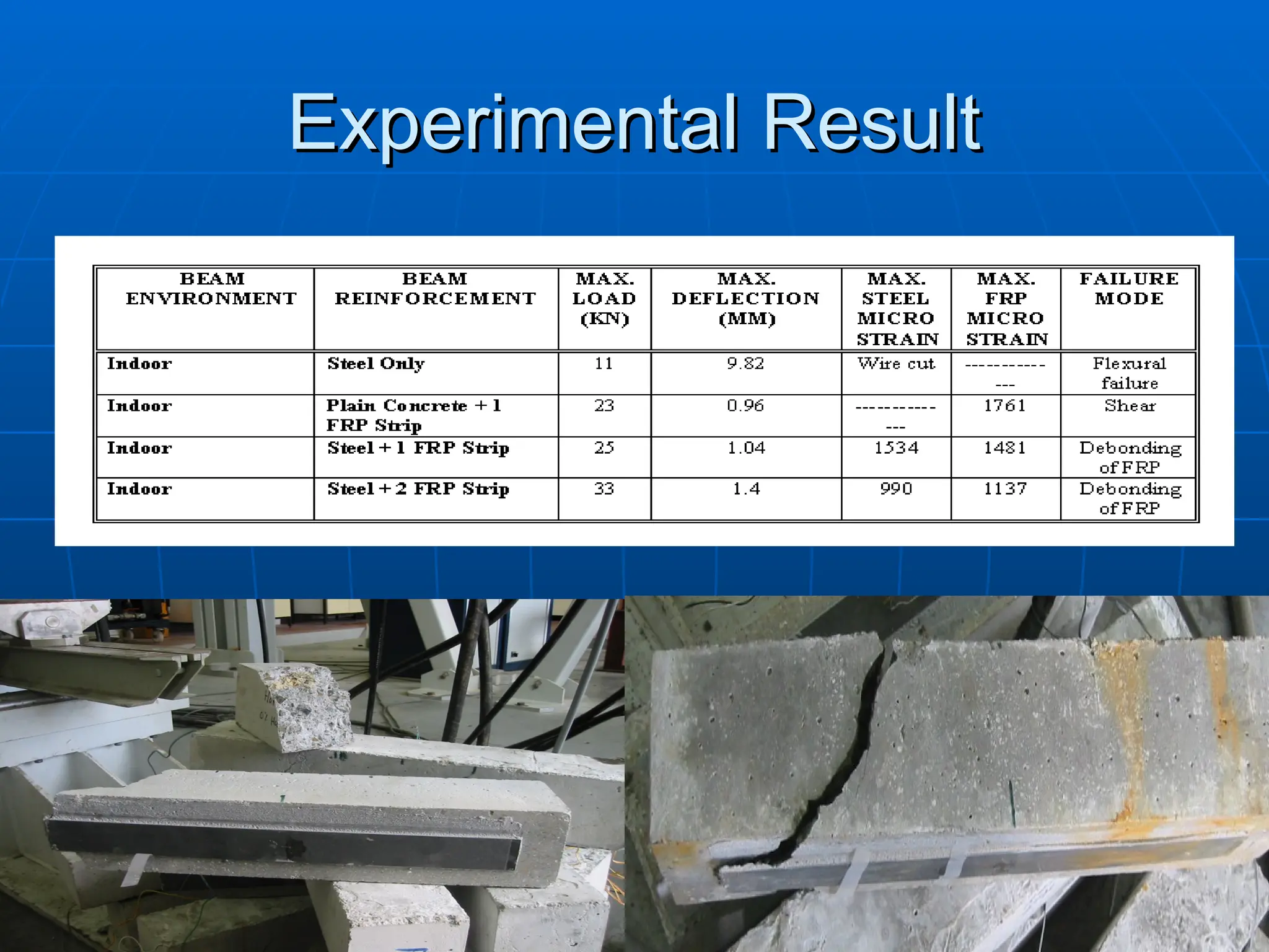
Beams Details
Beams Details
This experiment consists of 16 beams and 6 cubes.
This experiment consists of 16 beams and 6 cubes.
Beams were divided to 4 groups, each group consists
Beams were divided to 4 groups, each group consists
of 4 beams with four different reinforcements.
of 4 beams with four different reinforcements.
Beams dimensions were 10cm x 10cm x 50cm.
Beams dimensions were 10cm x 10cm x 50cm.
Minimum reinforcement of one bar with 6mm
Minimum reinforcement of one bar with 6mm
diameter (1
diameter (1Φ
Φ6) was used.
6) was used.
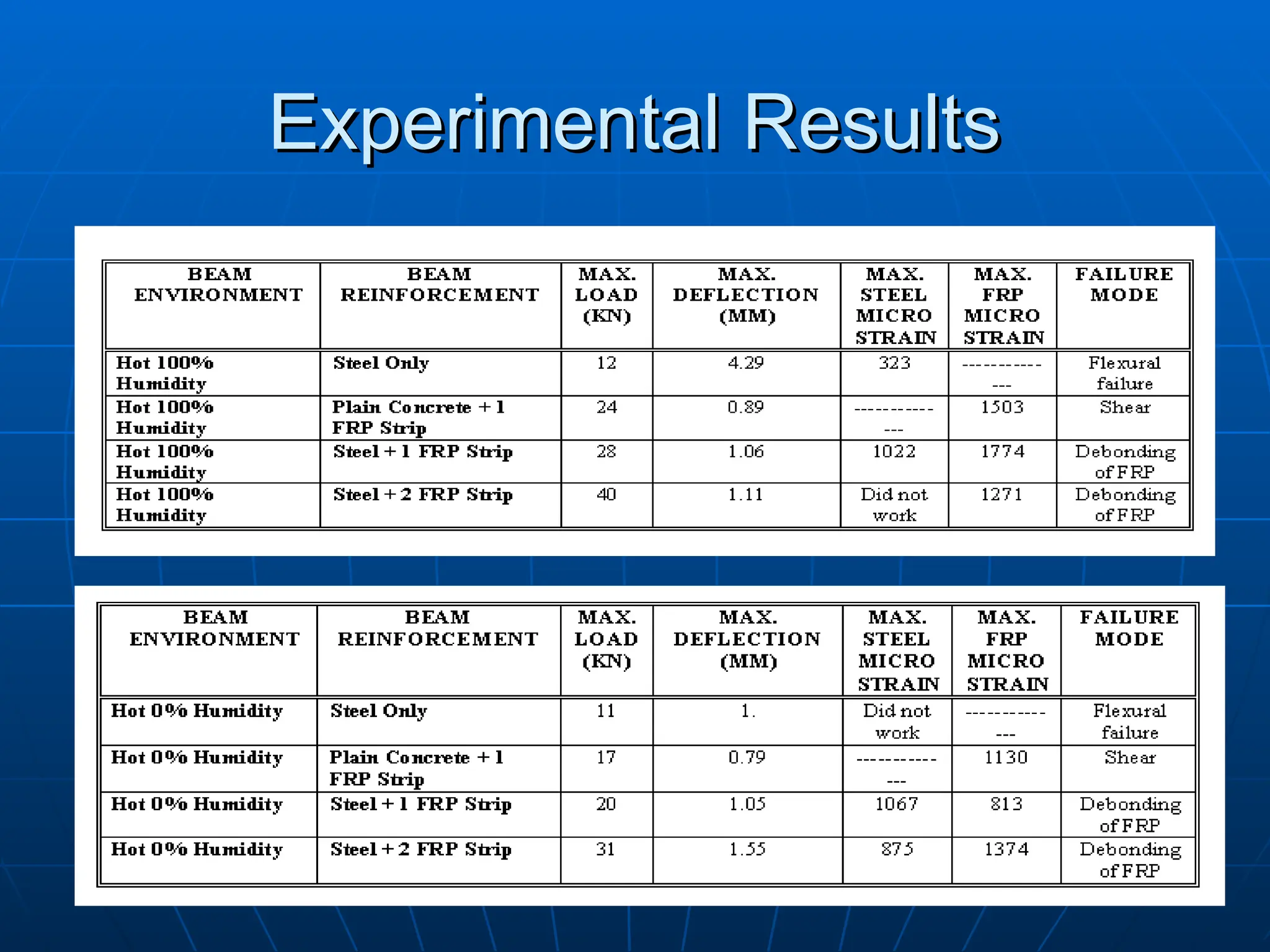
35.
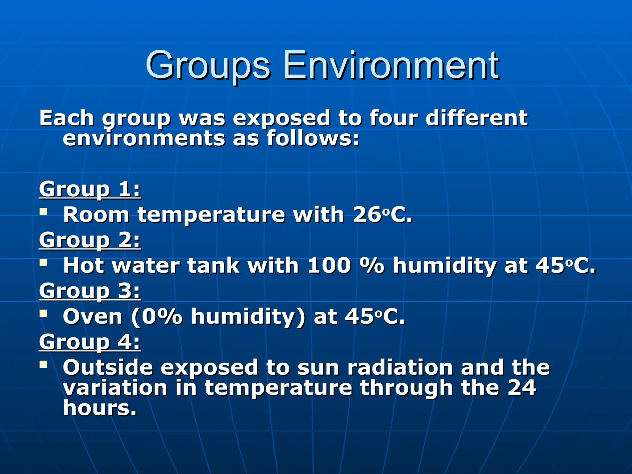
Groups Environment
Groups Environment
Eachgroup was exposed to four different
Each group was exposed to four different
environments as follows:
environments as follows:
Group 1:
Group 1:
Room temperature with 26
Room temperature with 26o
o
C.
C.
Group 2:
Group 2:
Hot water tank with 100 % humidity at 45
Hot water tank with 100 % humidity at 45o
o
C.
C.
Group 3:
Group 3:
Oven (0% humidity) at 45
Oven (0% humidity) at 45o
o
C.
C.
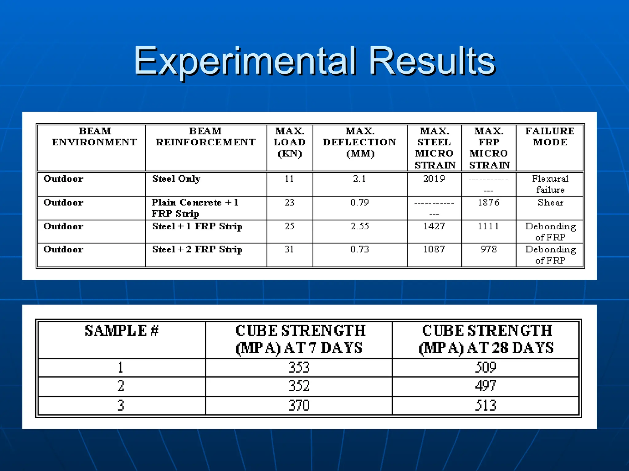
Group 4:
Group 4:
Outside exposed to sun radiation and the
Outside exposed to sun radiation and the
variation in temperature through the 24
variation in temperature through the 24
hours.
hours.
36.
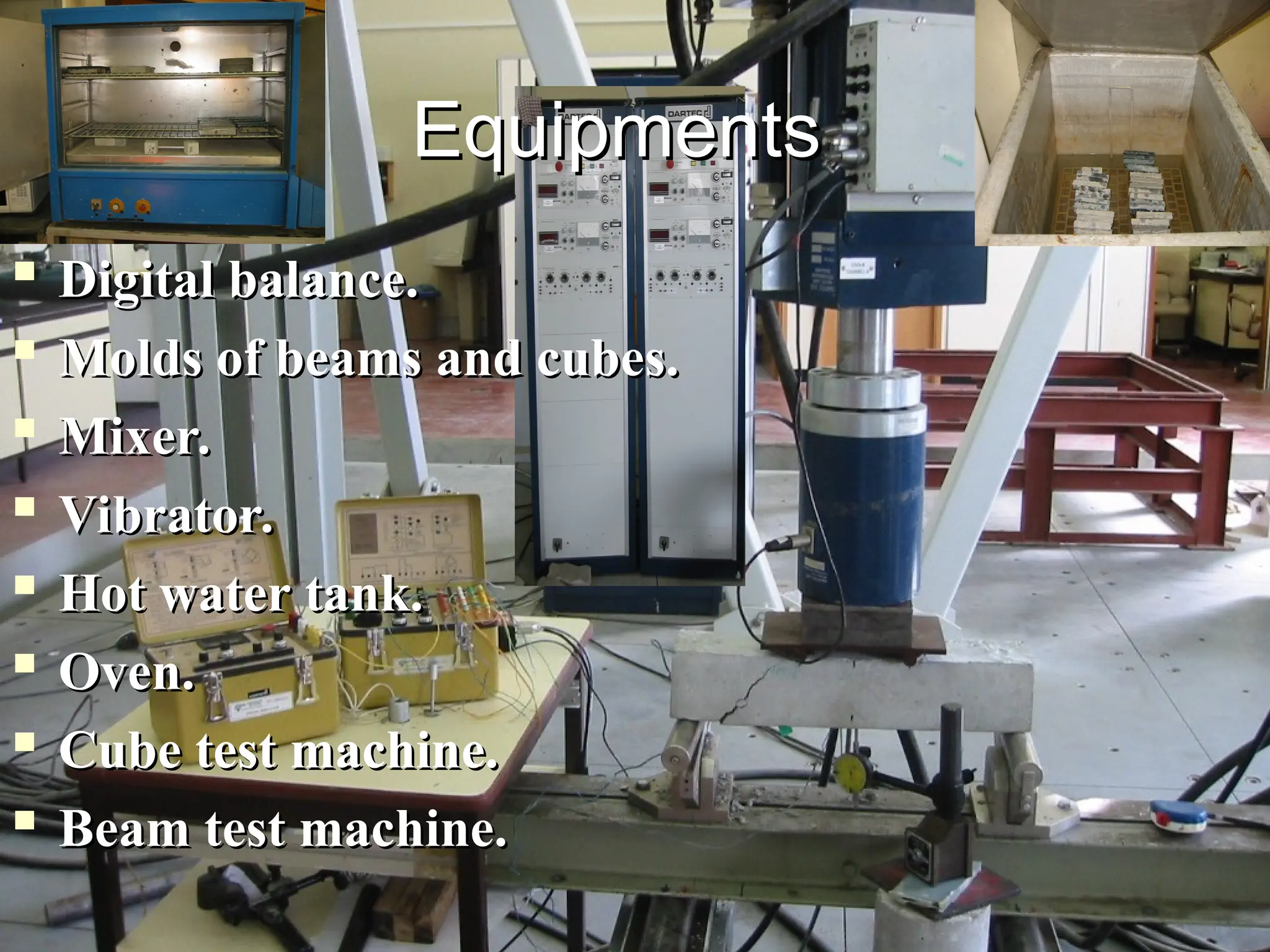
Digital balance.
Digital balance.
Moldsof beams and cubes.
Molds of beams and cubes.
Mixer.
Mixer.
Vibrator.
Vibrator.
Hot water tank.
Hot water tank.
Oven.
Oven.
Cube test machine.
Cube test machine.
Beam test machine.
Beam test machine.
Equipments
Equipments
37.
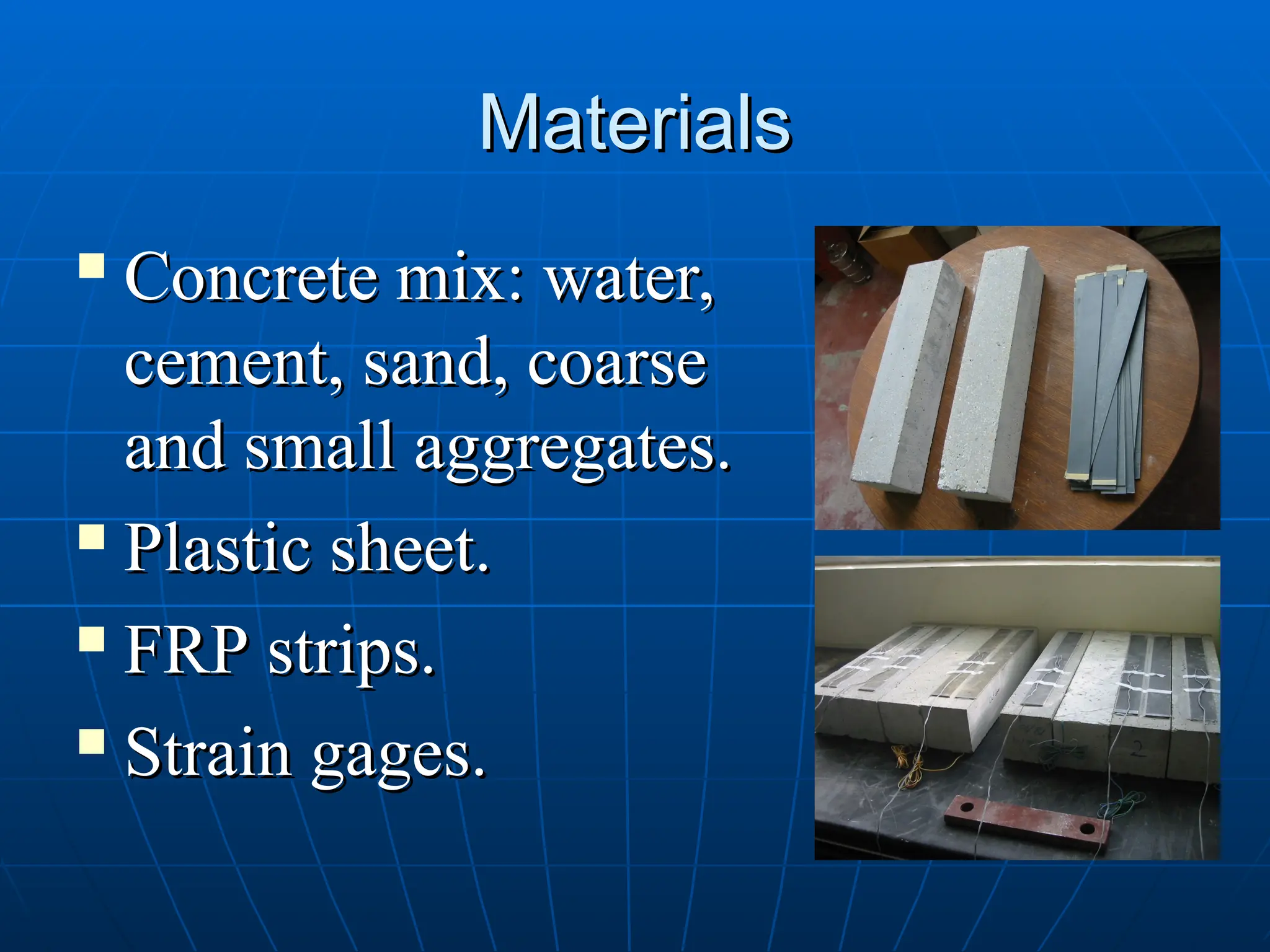
Materials
Materials
Concrete mix: water,
Concretemix: water,
cement, sand, coarse
cement, sand, coarse
and small aggregates.
and small aggregates.
Plastic sheet.
Plastic sheet.
FRP strips.
FRP strips.
Strain gages.
Strain gages.
38.
Procedures
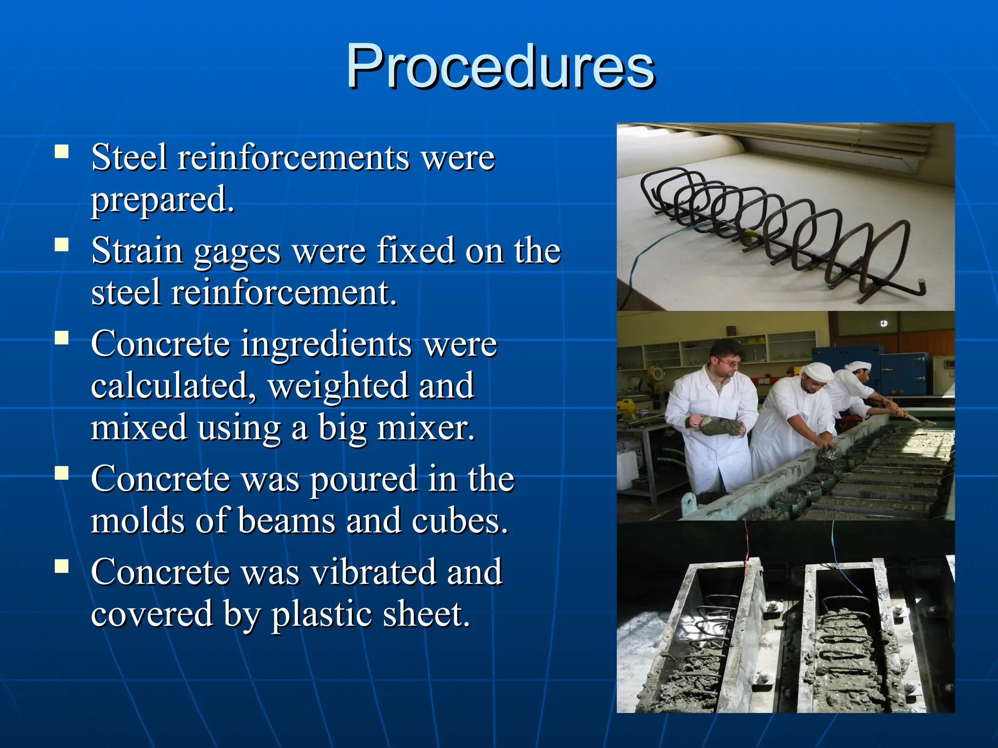
Procedures
Steel reinforcementswere
Steel reinforcements were
prepared.
prepared.
Strain gages were fixed on the
Strain gages were fixed on the
steel reinforcement.
steel reinforcement.
Concrete ingredients were
Concrete ingredients were
calculated, weighted and
calculated, weighted and
mixed using a big mixer.
mixed using a big mixer.
Concrete was poured in the
Concrete was poured in the
molds of beams and cubes.
molds of beams and cubes.
Concrete was vibrated and
Concrete was vibrated and
covered by plastic sheet.
covered by plastic sheet.
39.
Procedures
Procedures
3 cubes weretested after 7 days.
3 cubes were tested after 7 days.
Concrete beams and cubes were
Concrete beams and cubes were
removed from molds and cured in
removed from molds and cured in
potable water for 14 days.
potable water for 14 days.
Beams and cubes were exposed to
Beams and cubes were exposed to
air drying in laboratory.
air drying in laboratory.
40.
Procedures
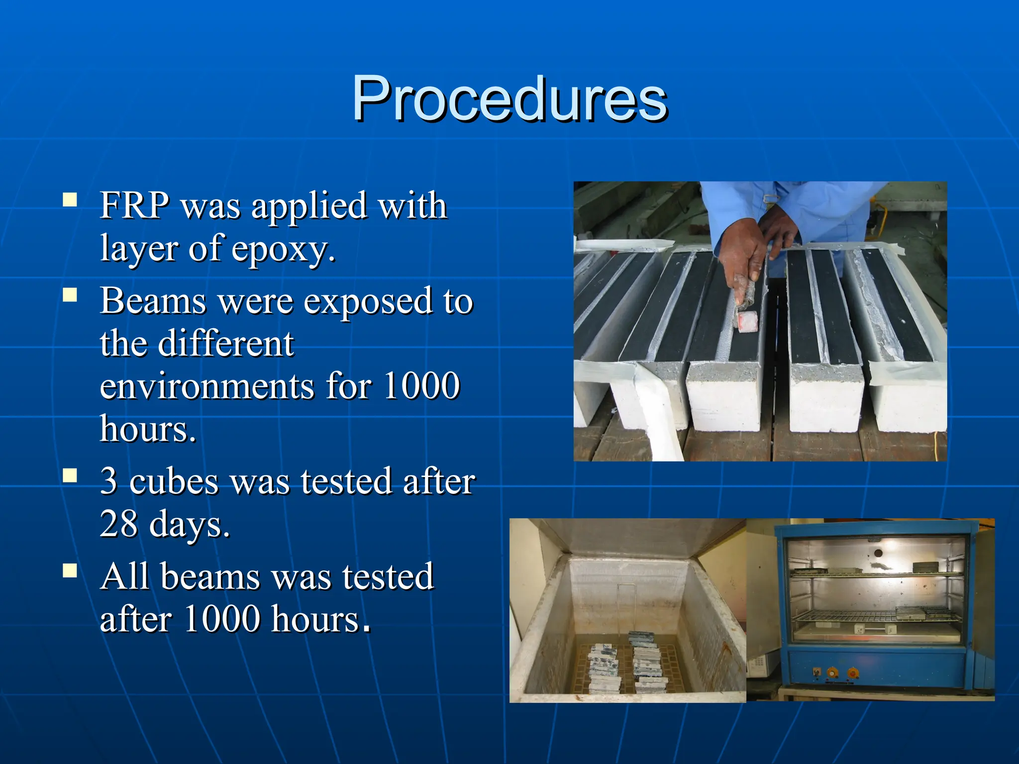
Procedures
FRP wasapplied with
FRP was applied with
layer of epoxy.
layer of epoxy.
Beams were exposed to
Beams were exposed to
the different
the different
environments for 1000
environments for 1000
hours.
hours.
3 cubes was tested after
3 cubes was tested after
28 days.
28 days.
All beams was tested
All beams was tested
after 1000 hours
after 1000 hours.
.
Experimental Observations
Experimental Observations
1.
1.Effect of Fiber Reinforcement Polymer
Effect of Fiber Reinforcement Polymer
(FRP) on strengthening the beams:
(FRP) on strengthening the beams:
One FRP strip increased the beam's capacity
One FRP strip increased the beam's capacity
by about 100% for all environments.
by about 100% for all environments.
Two strips of FRP increased the beam's
Two strips of FRP increased the beam's
capacity by about 200% for all environments.
capacity by about 200% for all environments.
All reinforced beams strengthen with FRP
All reinforced beams strengthen with FRP
failed on de-bonding of the FRP at the end of
failed on de-bonding of the FRP at the end of
strips due to the shear force at this location.
strips due to the shear force at this location.
45.
Experimental Observations
Experimental Observations
2.
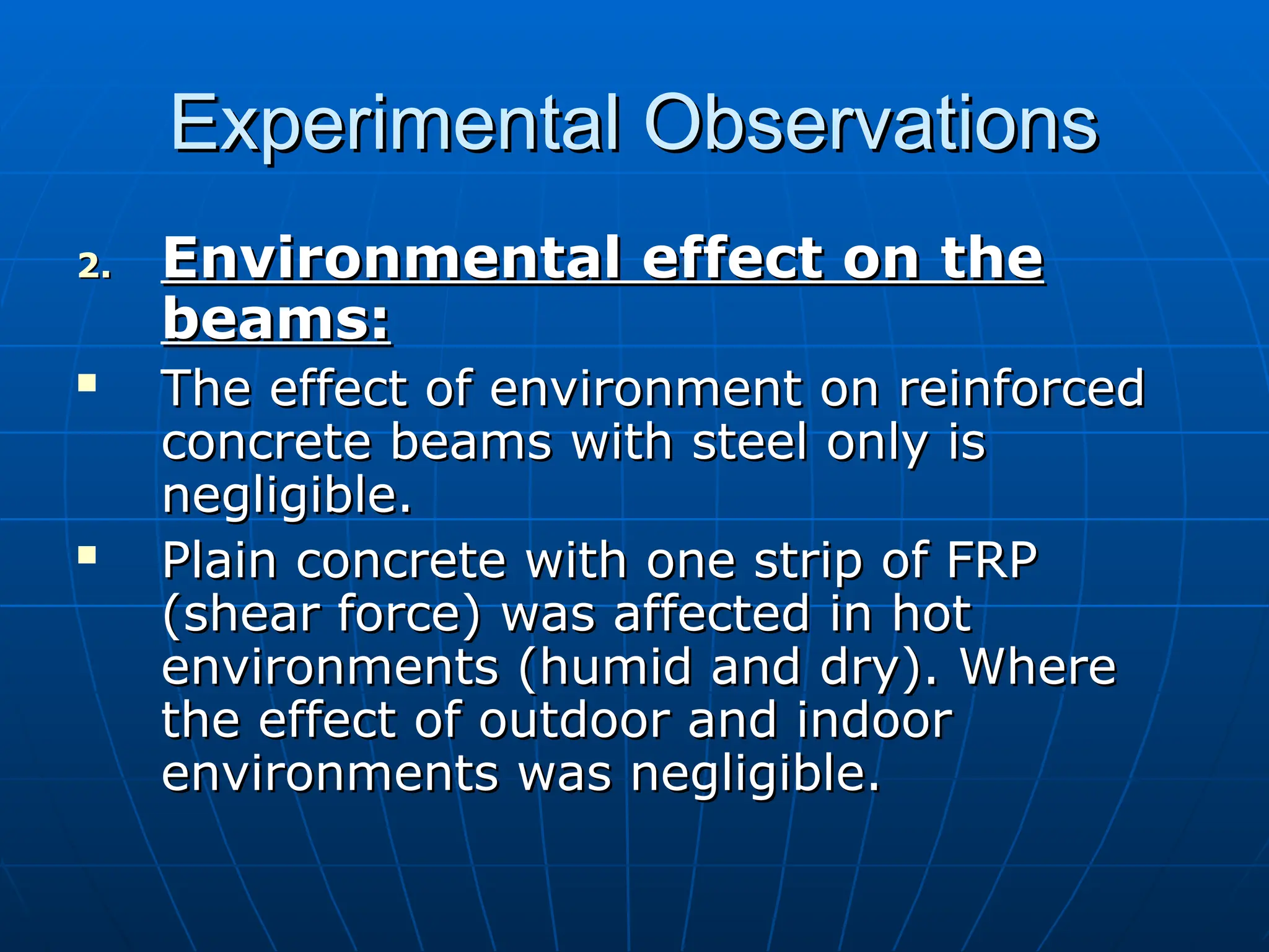
2.Environmental effect on the
Environmental effect on the
beams:
beams:
The effect of environment on reinforced
The effect of environment on reinforced
concrete beams with steel only is
concrete beams with steel only is
negligible.
negligible.
Plain concrete with one strip of FRP
Plain concrete with one strip of FRP
(shear force) was affected in hot
(shear force) was affected in hot
environments (humid and dry). Where
environments (humid and dry). Where
the effect of outdoor and indoor
the effect of outdoor and indoor
environments was negligible.
environments was negligible.
46.
Experimental Observations
Experimental Observations
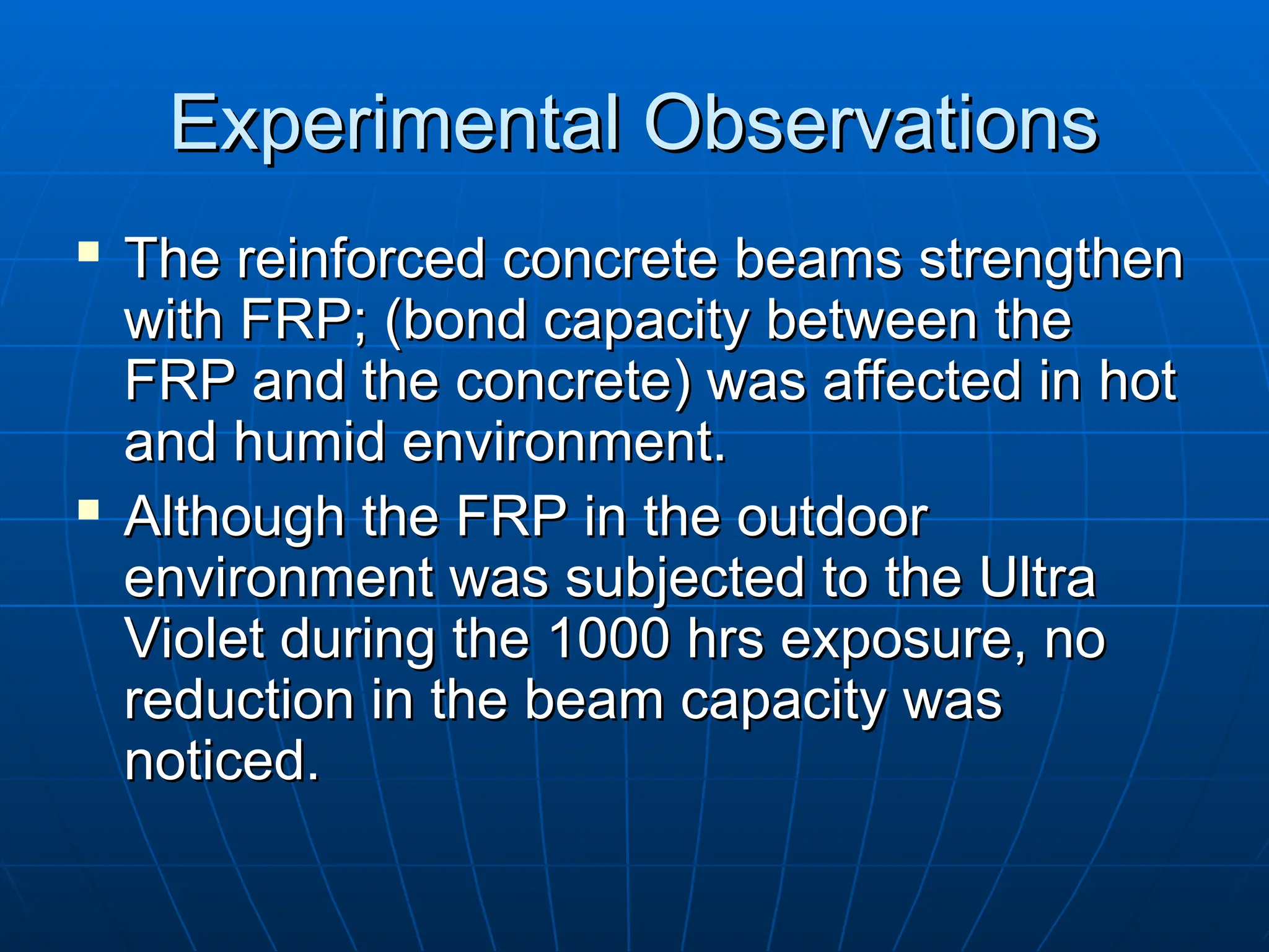
The reinforced concrete beams strengthen
The reinforced concrete beams strengthen
with FRP;
with FRP; (
(bond capacity between the
bond capacity between the
FRP and the concrete
FRP and the concrete)
) was affected in
was affected in hot
hot
and humid environment.
and humid environment.
Although the FRP in the outdoor
Although the FRP in the outdoor
environment was subjected to the Ultra
environment was subjected to the Ultra
Violet during the 1000 hrs exposure, no
Violet during the 1000 hrs exposure, no
reduction in the beam capacity was
reduction in the beam capacity was
noticed.
noticed.
47.
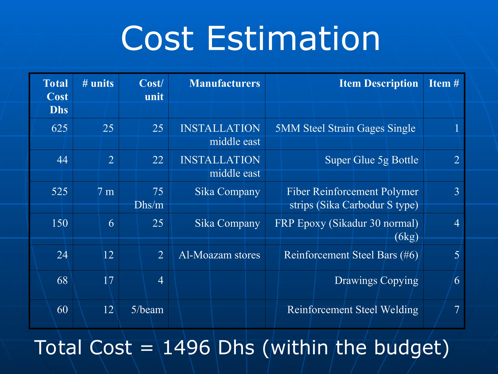
Cost Estimation
Total Cost= 1496 Dhs (within the budget)
Item #
Item Description
Manufacturers
Cost/
unit
# units
Total
Cost
Dhs
1
5MM Steel Strain Gages Single
INSTALLATION
middle east
25
25
625
2
Super Glue 5g Bottle
INSTALLATION
middle east
22
2
44
3
Fiber Reinforcement Polymer
strips (Sika Carbodur S type)
Sika Company
75
Dhs/m
7 m
525
4
FRP Epoxy (Sikadur 30 normal)
(6kg)
Sika Company
25
6
150
5
Reinforcement Steel Bars (#6)
Al-Moazam stores
2
12
24
6
Drawings Copying
4
17
68
7
Reinforcement Steel Welding
5/beam
12
60
48.
Analysis background
Analysis background
Themost important and most
The most important and most
difficult task faced by the structural
difficult task faced by the structural
designer is the accurate estimation
designer is the accurate estimation
of the loads that may be applied to
of the loads that may be applied to
the structure during its life.
the structure during its life.
The next problem is to decide the
The next problem is to decide the
worst possible combinations of these
worst possible combinations of these
loads that might occur at one time.
loads that might occur at one time.
49.
Analysis background
Analysis background
Theloads that will be used in this
The loads that will be used in this
project are dead and live loads.
project are dead and live loads.
Dead loads are loads of constant
Dead loads are loads of constant
magnitude that remain in one
magnitude that remain in one
position.
position.
Live loads are loads that can change
Live loads are loads that can change
in magnitude and position.
in magnitude and position.
50.
Analysis background
Analysis background
ACIcode (9.2) states that the
ACI code (9.2) states that the
required ultimate load carrying
required ultimate load carrying
ability of the member U provided to
ability of the member U provided to
resist the dead load D and the live
resist the dead load D and the live
load L must at least equal:
load L must at least equal:
U = 1.4D + 1.7L
U = 1.4D + 1.7L
51.
Analysis background
Analysis background
TheLoads carried by the structure are
The Loads carried by the structure are
transferred from one structural element to
transferred from one structural element to
another until it reaches its final destination
another until it reaches its final destination
to the supporting ground.
to the supporting ground.
The loads that come from slabs to beams
The loads that come from slabs to beams
can be estimated according to the slabs
can be estimated according to the slabs
design system and the geometry of these
design system and the geometry of these
slabs.
slabs.
52.
Analysis background
Analysis background
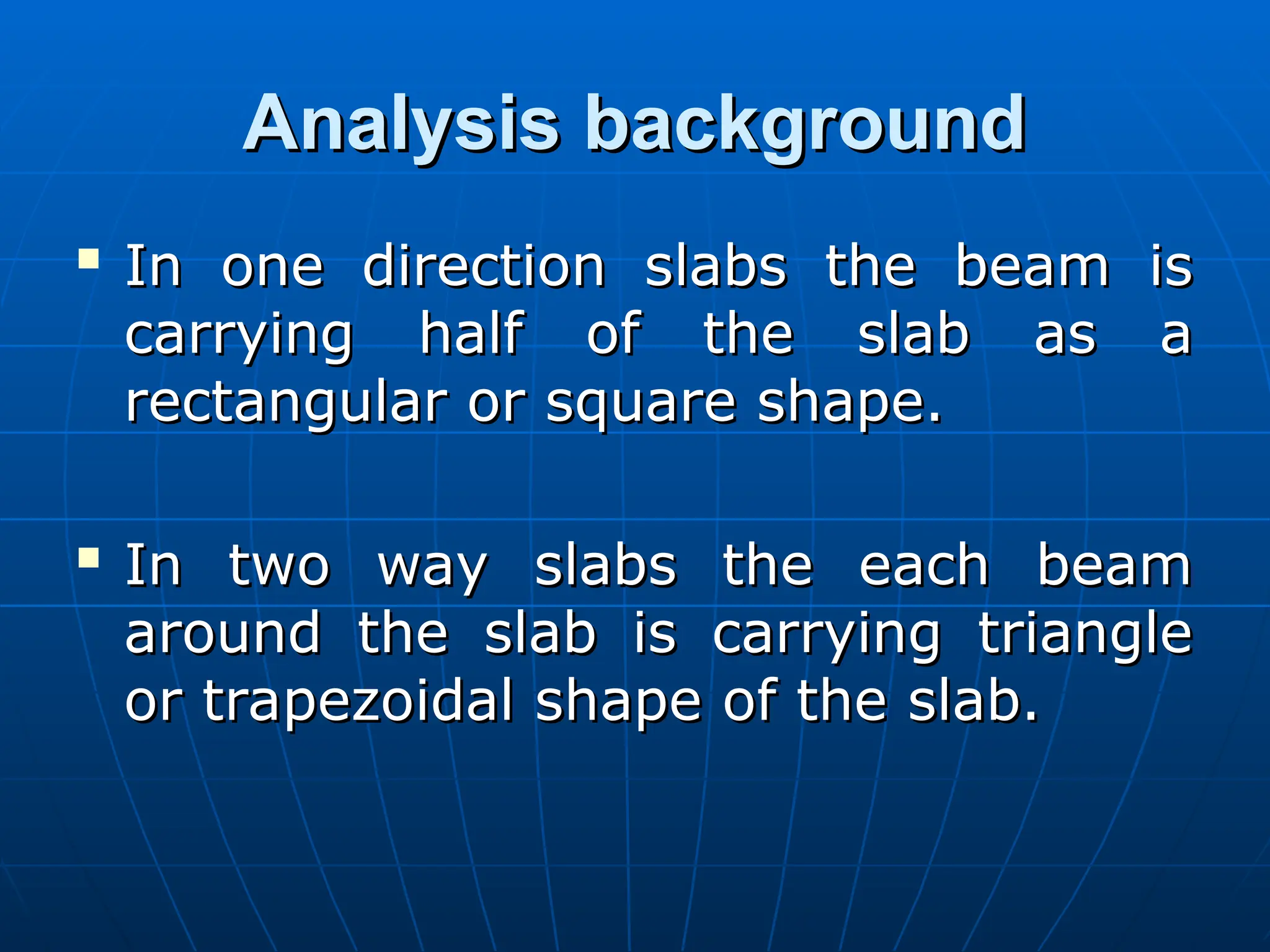
Inone direction slabs the beam is
In one direction slabs the beam is
carrying half of the slab as a
carrying half of the slab as a
rectangular or square shape.
rectangular or square shape.
In two way slabs the each beam
In two way slabs the each beam
around the slab is carrying triangle
around the slab is carrying triangle
or trapezoidal shape of the slab.
or trapezoidal shape of the slab.
53.
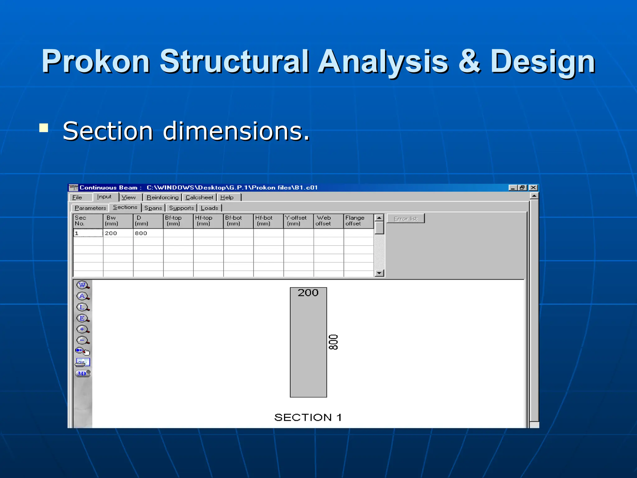
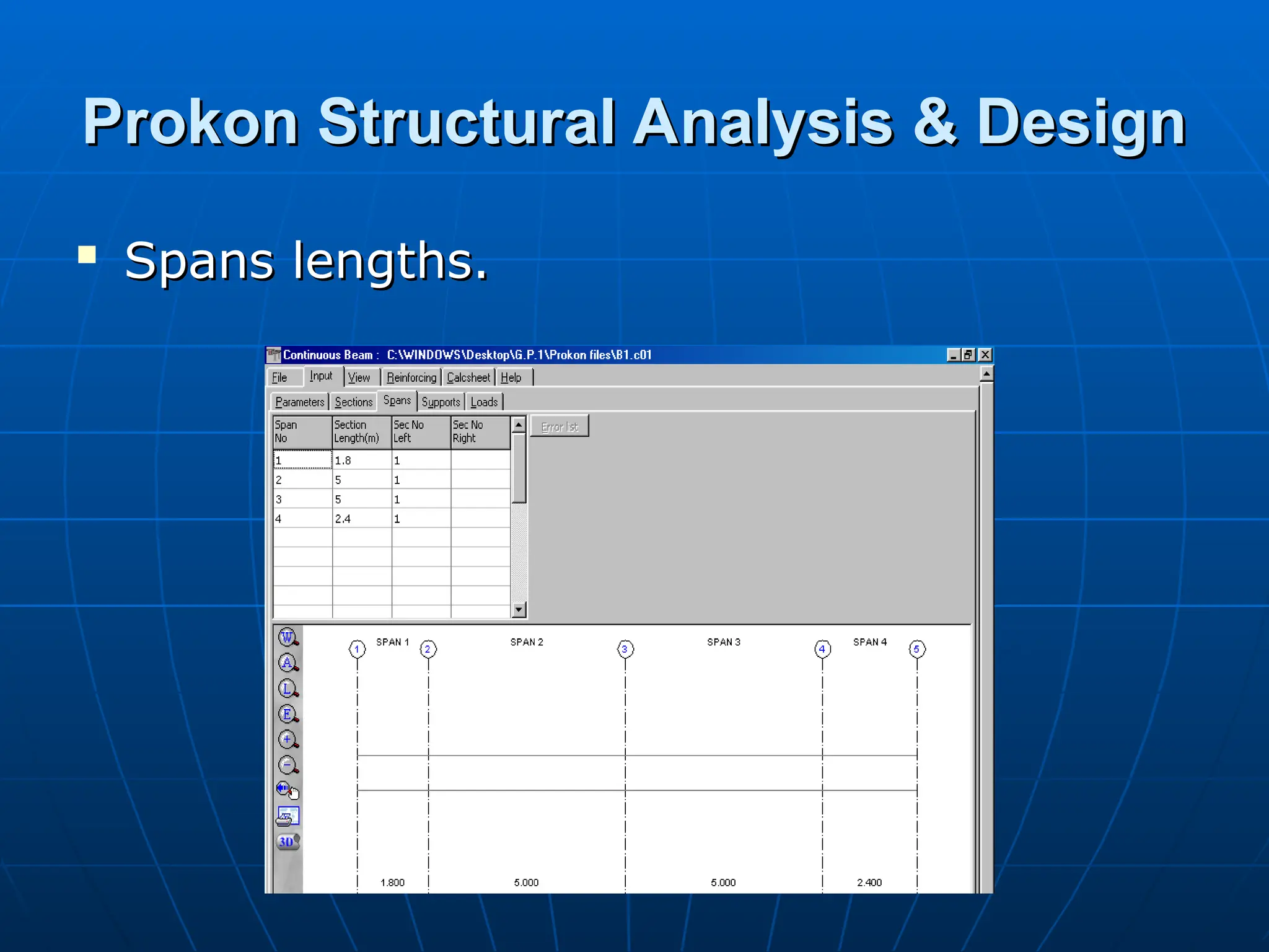
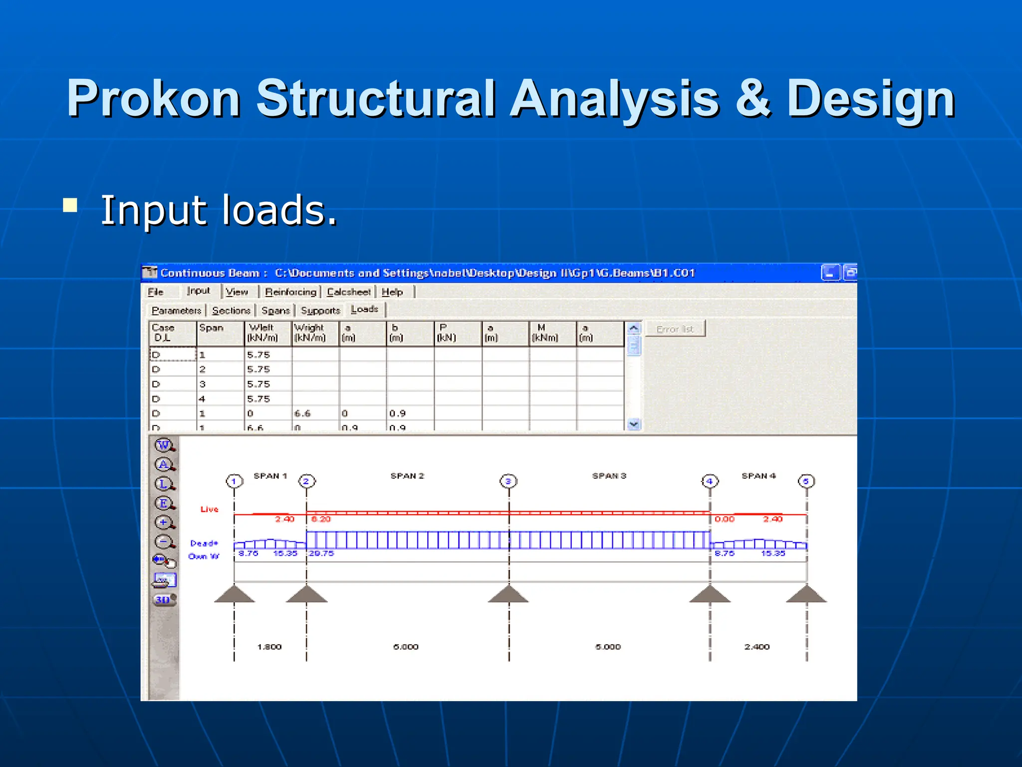
Prokon Structural Analysis& Design
Prokon Structural Analysis & Design
Prokon structural analysis and design
Prokon structural analysis and design
is a useful tool for analysis and
is a useful tool for analysis and
design of structures.
design of structures.
The PROKON suite has two main
The PROKON suite has two main
components:
components:
PROKON Calcpad.
PROKON Calcpad.
PROKON analysis and design
PROKON analysis and design
modules .
modules .
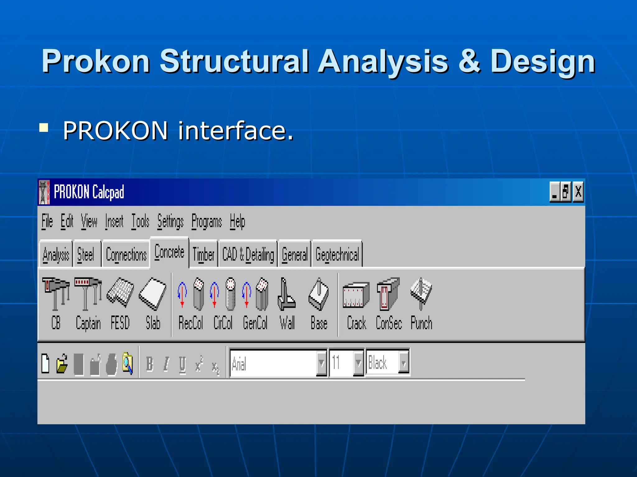
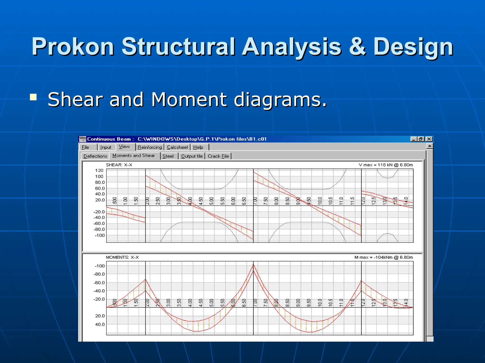
Prokon Structural Analysis& Design
Prokon Structural Analysis & Design
Shear and Moment diagrams
Shear and Moment diagrams.
.
60.
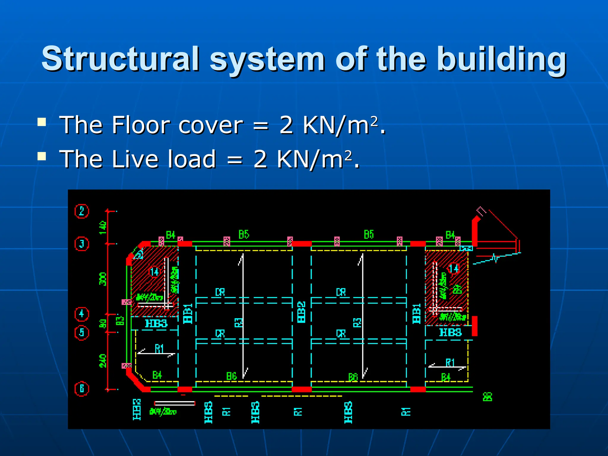
Structural system ofthe building
Structural system of the building
Area = 750 m
Area = 750 m2
2
.
.
It consists of two stories.
It consists of two stories.
Types of slabs: One way Hurdy
Types of slabs: One way Hurdy
slabs, two way hurdy slabs and two
slabs, two way hurdy slabs and two
way solid slabs.
way solid slabs.
Types of columns: Rectangular and
Types of columns: Rectangular and
circular.
circular.
There are projected beams and
There are projected beams and
hidden beams.
hidden beams.
61.
Structural system ofthe building
Structural system of the building
The Floor cover = 2 KN/m
The Floor cover = 2 KN/m2
2
.
.
The Live load = 2 KN/m
The Live load = 2 KN/m2
2
.
.
62.
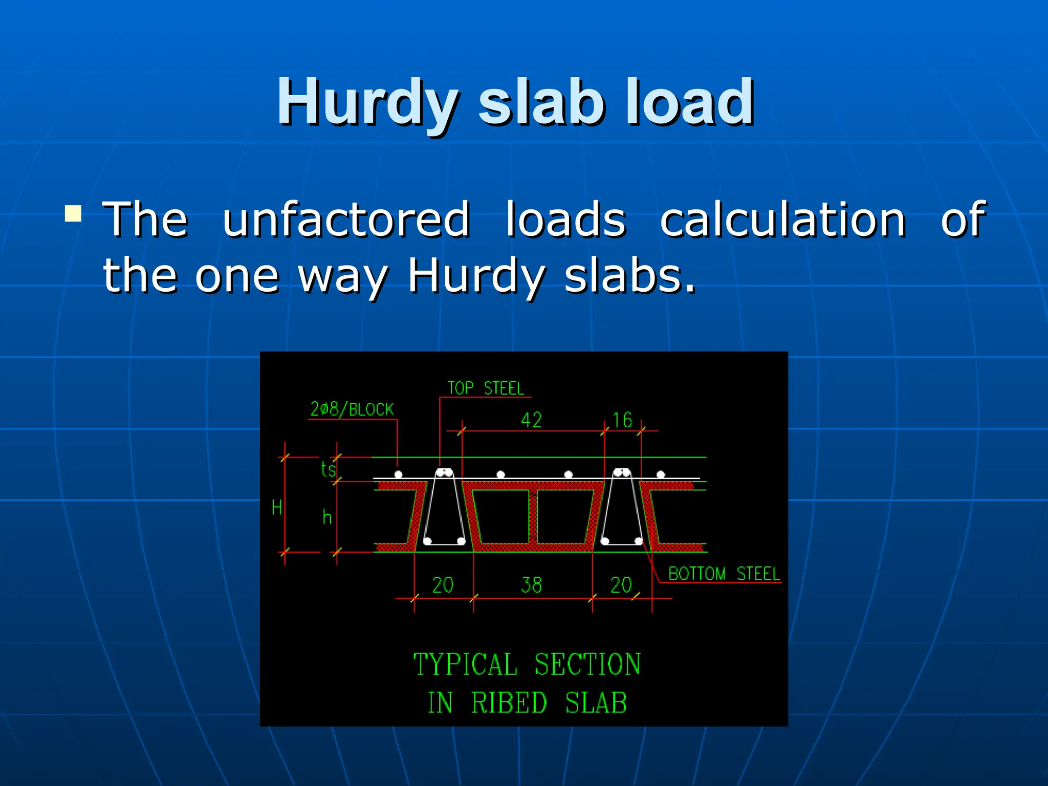
Hurdy slab load
Hurdyslab load
The unfactored loads calculation of
The unfactored loads calculation of
the one way Hurdy slabs.
the one way Hurdy slabs.
63.
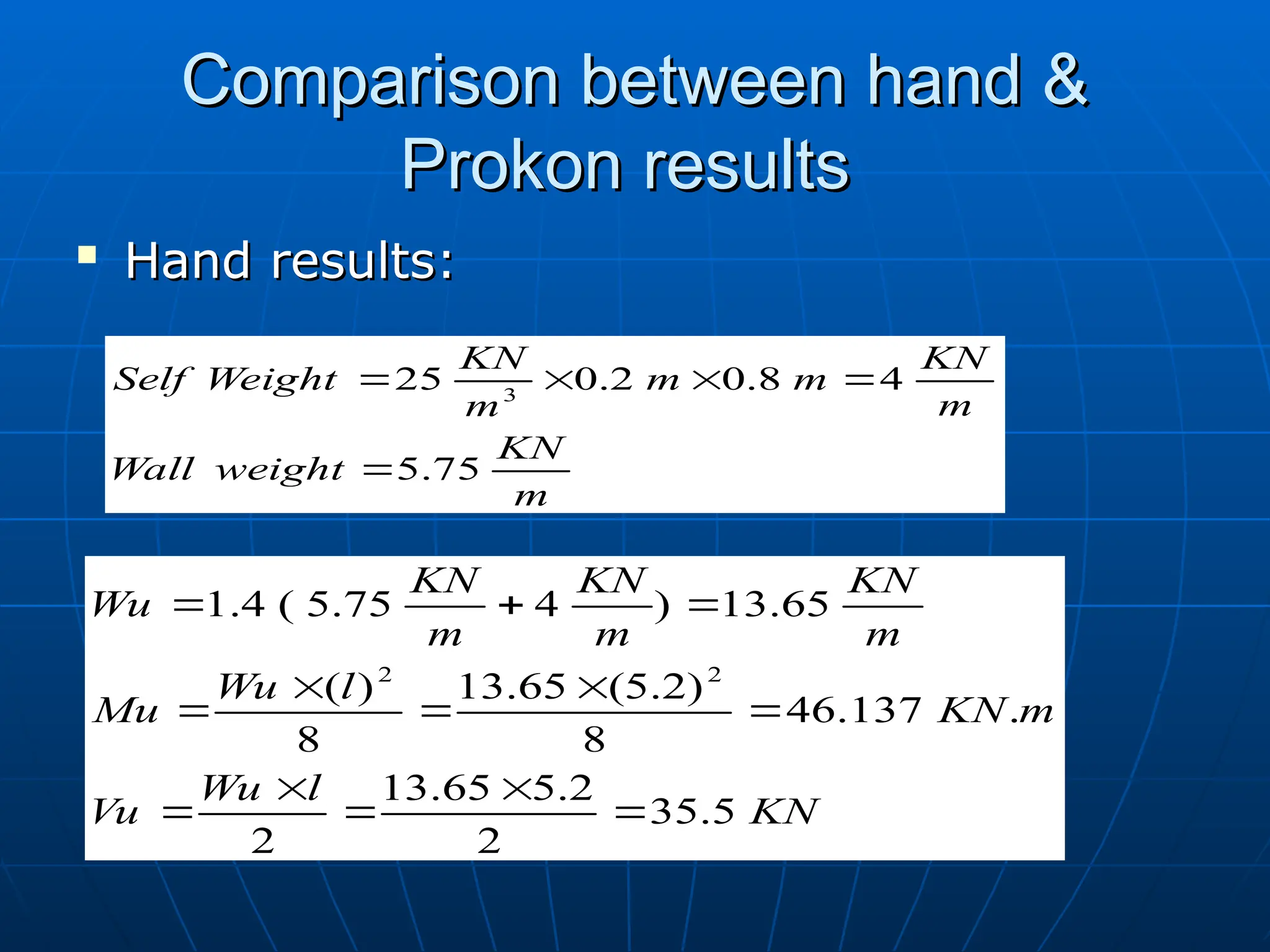
Comparison between hand&
Comparison between hand &
Prokon results
Prokon results
Hand results:
Hand results:
m
KN
weight
Wall
m
KN
m
m
m
KN
Weight
Self
75
.
5
4
8
.
0
2
.
0
25 3
KN
l
Wu
Vu
m
KN
l
Wu
Mu
m
KN
m
KN
m
KN
Wu
5
.
35
2
2
.
5
65
.
13
2
.
137
.
46
8
)
2
.
5
(
65
.
13
8
)
(
65
.
13
)
4
75
.
5
(
4
.
1
2
2
64.
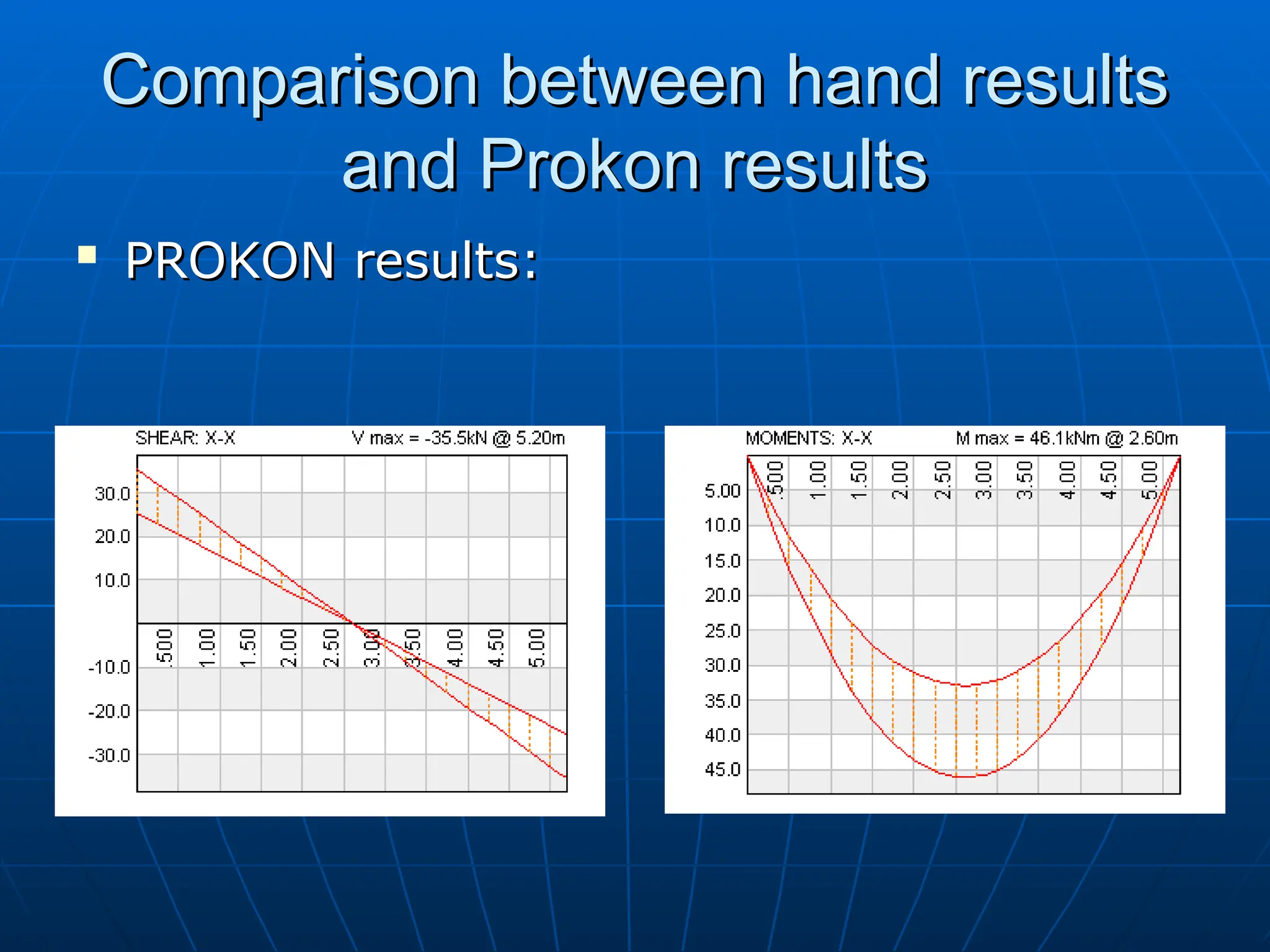
Comparison between handresults
Comparison between hand results
and Prokon results
and Prokon results
PROKON results:
PROKON results:
65.
Conclusion
Conclusion
It was learnedsome modern
It was learned some modern
technologies in strengthening
technologies in strengthening
concrete structures.
concrete structures.
It was learned a new computer
It was learned a new computer
software program.
software program.
The a knowledge that we gained
The a knowledge that we gained
from structural analysis and design
from structural analysis and design
courses were applied.
courses were applied.
66.
Conclusion
Conclusion
From the experimentalresults, it was
From the experimental results, it was
found that the FRP was effected by
found that the FRP was effected by
20 % in the hot (0% humidity)
20 % in the hot (0% humidity)
environment.
environment.
It was decided to use FRP to strength
It was decided to use FRP to strength
the building.
the building.
It was learned how to analyze one
It was learned how to analyze one
way Hurdy slabs and beams.
way Hurdy slabs and beams.


![[BROCHURE] Italy Tour Project | @SlideON](https://cdn.slidesharecdn.com/ss_thumbnails/brochure8-251215152319-2805af68-thumbnail.jpg?width=640&height=640&fit=bounds)


