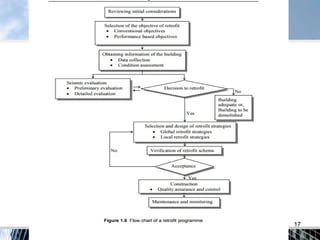
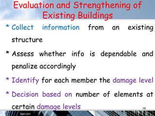
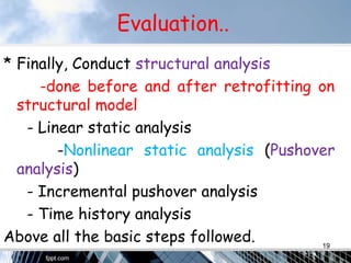
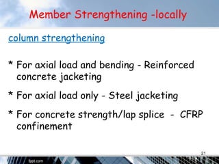
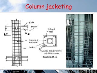
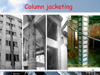
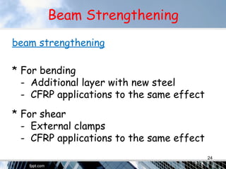
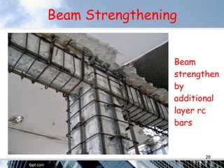
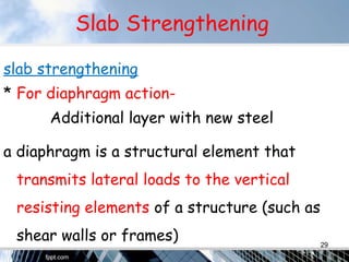
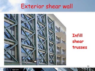
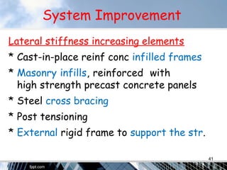
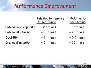
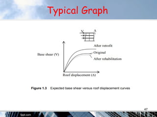
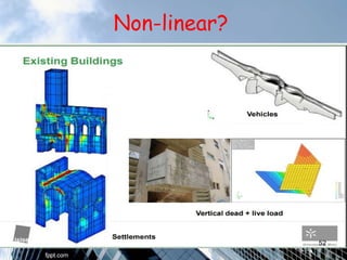
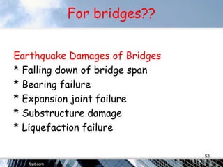
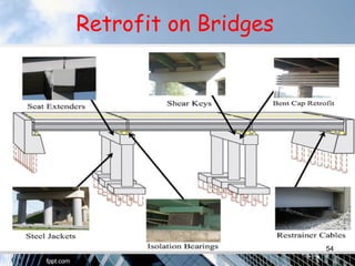
SEISMIC RETROFITTING
ON RC STRUCTURES
AN OVERVIEW M.Ramesh
M.E. Structural,Ceg
Introduction
“Earthquake” is a natural phenomenon
* It is tolerable in countries where the
people and the built environment are
prepared for it;
* It leads to a disaster in countries where
the built environment and the people
are not prepared for it.
2
Introduction
“Earthquake Preparedness” consists of
* Disaster Management (post-quake) –
Search & rescue, sheltering, food,
medical care etc. (Easy but not effective)
* Risk Management (pre-quake) – Safe
towns, safe structures, well educated
public, well trained engineers, effective
financing etc. (Hard but very effective)
3
Introduction
* Seismic rehab of the existing bldg
stock is the most critical item in risk
mitigation(control).
* A huge unsafe building stock exists.
* A systematic assessment reveals that
- A small number is seismically safe,
- A certain portion is to be demolished,
- The majority is to be strengthened.
4
Objective
The objective of seismic resistant design no
structural/nonstructural damage in low
magnitude earthquakes, limited and
repairable damage in moderate
earthquakes and life safety for extreme
earthquakes.
5
COMMON
STRUCTURAL
SYSTEM
6
Common Type Of Str
* Reinforced concrete framed building
structures are common in India .
* Partitioning walls of hollow/normal brick
masonry make the structure infilled frame.
* Risk Seismic zones (changes per code)
* 29 Indian cities including Delhi- as per NCS –
Ministry of Earth Science
(Case: EB office building ,Chennai.) 7
Common Defıcıencıes
RC framed building structures with brick
masonry infill,
* Low-rise (1∼2 floor) are not vulnerable;
* High-rise (> 10∼12 floor) buildings are .
carefully designed and constructed;
* Mid-rise (3∼8floor) bldgs of inferior .
material, poor design and construction .
quality present the major problem.
8
Common Defıcıencıes
Mid-rise buildings of inferior quality
* Constitute the majority in small towns;
* Collapse in the pancake mode; thus
* Are responsible from the high number
of human losses and severe damage,
* Are generally too good for demolition;
* Are greatly in need of rehabilitation.
9
Common Defıcıencıes
Common deficiencies of such buildings:
* Insufficient lateral stiffness
* Deficient reinforcement detailing
* Deficient design practice
* Poor concrete
* poor workmanship etc.
10
Retrofit versus Repair and Rehabilitation
• Repair: actions improve functionality , as-built
system, rectify the observed defects, non
structural ,if carried out on structural
elements unlikely to enhance structural
strength, doesn’t guarantee structural safety
(especially to dynamic forces), involves
patching cracks and falling plaster, fixing
doors windows etc., 11
Rehabilitation
* Rehabilitation structural interventions to
improve strength of buildings which
deteriorated or damaged
* intended to regain its original strength of
the member by strengthen or replace the
structural systems, removal or rebuilding the
damaged walls 12
Rehabilitation
* grouting(injection of materials) and
guniting (A cement gun used under a
pressure of about 20 to 30 N/cm2
)
damaged concrete structures,
* underpinning, adaptation of vacant
schools into apartments, warehouses into
offices etc., 13
Retrofit
* Retrofit specifically aims to enhance the
structural capacities (stability and integrity)
which are vulnerable or deficient
* Seismic rehabilitation, seismic upgradation
And seismic strengthening – seismic retrofit
14
Retrofit
* Building need not to be damaged or
deteriorated
* Intended to mitigate the effect of a
future earthquake
* It includes the providing of additional
parts to structures
15
Seismic Retrofitting
A Seismic Retrofit provides existing
structures with more resistance to
seismic activity due to earthquakes. In
buildings, this process typically includes
strengthening weak connections found in
roof to wall connections, continuity ties,
shear walls and the roof diaphragm. 16
17
Evaluation and Strengthening of
Existing Buildings
* Collect information from an existing
structure
* Assess whether info is dependable and
penalize accordingly
* Identify for each member the damage level
* Decision based on number of elements at
certain damage levels 18
Evaluation..
* Finally, Conduct structural analysis
-done before and after retrofitting on
structural model
- Linear static analysis
-Nonlinear static analysis (Pushover
analysis)
- Incremental pushover analysis
- Time history analysis
Above all the basic steps followed. 19
REHABILITATION/retrofit
TECHNIQUES
AVAILABLE
20
Member Strengthening -locally
column strengthening
* For axial load and bending - Reinforced
concrete jacketing
* For axial load only - Steel jacketing
* For concrete strength/lap splice - CFRP
confinement
21
Column jacketing
22
Column jacketing
23
Beam Strengthening
beam strengthening
* For bending
- Additional layer with new steel
- CFRP applications to the same effect
* For shear
- External clamps
- CFRP applications to the same effect
24
CERP
* CFRP – Carbon Fiber Reinforced Polymer
modern techq.
* strong but brittle.
* light weight, high tensile strength material
and advantage of fast implementation.
* increase strength and stiffness of RC
frames. 25
CERP
* The effectiveness is strongly dependent
on the extent of anchorage between the
FRP strips and the frame.
* cannot be used for longitudinal bars in
rc bldgs at plastic hinge regions
* cannot be employed for a energy
absorbing material 26
CERP
* where the longitudinal bars play a role
of energy absorbing devices.
* employed for transverse reinforcement
to which plastic deformation is not
required, and for the longitudinal
reinforcement in the region where large
plastic deformation is not expected .. 27
Beam Strengthening
Beam
strengthen
by
additional
layer rc
bars
28
Slab Strengthening
slab strengthening
* For diaphragm action-
Additional layer with new steel
a diaphragm is a structural element that
transmits lateral loads to the vertical
resisting elements of a structure (such as
shear walls or frames) 29
Joint Strengthening
joint strengthening
* For shear - Diagonal steel/CFRP dovels
- External clamps
- Confining devices
- Ensure Ductile behavior
30
Exterior shear wall
Infill
shear
trusses
31
Push-over analysis
* Push-over analysis purpose of the is to
evaluate the expected performance of
a structural system by estimating its
strength and deformation demands in
designing earthquake resistant
buildings by means of a static nonlinear
analysis. 32
Push-over Analysis
* Traditional force method, combined
with control of performance
requirements based on deformation
* Displacement based method, in which
the analysis starts by defining a target
displacement (measuring the structural
response). 33
Outline
* the performance level of structural
members were evaluated for all
structures, before and after
retrofitting
* The structural model of the building is
prepared in SAP2000 or ETABS and
results are interpolated 34
Outline
* All the beams and columns are modelled
as frame element and slab is modelled
as shell elements.
* Infill walls are not considered in the
structural model.
* The jacketed portions of brick walls
adjacent to the columns are accounted 35
Outline
for in the structural model by increasing
the sizes of the columns
* the stiffness of the columns and adjacent
walls combined is equal to the stiffness of
the idealized columns of increased sizes.
* Result gives us information on displacements
which are indicators of amount of retrofit.36
Outline
* Now, push-over analysis (push in N-S or
E-W) is performed on this retrofitted
structure as per the methodologies.
* It is an effective tool to evaluate
performance level of structures.
37
Sysyem Behaviour
Improvement
Techniques
38
System Improvement
Devices reducing seismic loads
* Base isolation
* Active / passive control
* Smart structures
* Dampers
* Energy absorbers etc. 39
Devices gives
Sa-
Spectral
Response
acceleration
Significantly Increase the Period of the
Structure and the Damping so that the
Response is Significantly Reduced.
40
System Improvement
Lateral stiffness increasing elements
* Cast-in-place reinf conc infilled frames
* Masonry infills, reinforced with
high strength precast concrete panels
* Steel cross bracing
* Post tensioning
* External rigid frame to support the str.
41
AN INNOVATIVE
REHABILITATION
TECHNIQUE
42
The basic question:
* Cast-in-place reif conc infilled frame
technique is suitable for post-quake
repair of the evacuated buildings; but not
for pre-quake rehabilitation of the
buildings still in use.
* Suitable techniques should be developed.
43
The Challenge
To develop a rehabilitation method,
* Suitable for the common building type
(Hollow brick infilled RC frame)
* Practical & economical, and above all
* Occupant friendly (no more disturbance
than an ordinary painting job)
44
Answer
The answer is OFR (occupant friendly rehab.)
* To reinforce existing masonry infill wall
with epoxy bonded PC panels, which are,
- Light enough to be handled by two
- Small enough to go through doors
- Relatively thin, 40~50 mm (high str.)
- Connected to infill wall by epoxy, and
to frame by epoxy bonded dowels
45
Performance Improvement
Relative to masonry Relative to
infilled frame bare frame
Lateral load capacity ∼2.5 times ∼ 15 times
Lateral stiffness ∼ 3 times ∼ 20 times
Ductility ∼ 2 times ∼ 0.2 times
Energy dissipation ∼ 3 times ∼ 60 times
46
Typical Graph
47
Conclusion
* Numerous types of structures may
benefit from a seismic retrofit,
including bridges, dams, etc…
* It has matured in the recent years to a
highly reliable technology.
* But, the expertise needed is not
available in the basic level. 48
Conclusion
* Optimization techniques are needed to
know the most efficient retrofit for a
particular structure.
* Proper Design Codes are needed to be
published as code of practice for
professionals related to this field.
49
Questions?
50
Non-Linear?
Assumptions in Linear analysis:
* Materials are being treated as linear
* Forces are being applied slowly and don’t
change direction in time
* Load and Deformations are interrelated( if
M gives D , 2D caused by 2M)
* designed based on inaccurate assumptions51
Non-linear?
52
For bridges??
Earthquake Damages of Bridges
* Falling down of bridge span
* Bearing failure
* Expansion joint failure
* Substructure damage
* Liquefaction failure
53
Retrofit on Bridges
54
For irrigation structures
* Sheet piling – control the water
pressure underneath the soil
* Laying aprons (protection against
barrage by shoulders – concrete)
* Replacement of barrage gates
55

Seismic Retrofitting On RC Structures-Pushover Analysis

  • 1.
    SEISMIC RETROFITTING ON RCSTRUCTURES AN OVERVIEW M.Ramesh M.E. Structural,Ceg
  • 2.
    Introduction “Earthquake” is anatural phenomenon * It is tolerable in countries where the people and the built environment are prepared for it; * It leads to a disaster in countries where the built environment and the people are not prepared for it. 2
  • 3.
    Introduction “Earthquake Preparedness” consistsof * Disaster Management (post-quake) – Search & rescue, sheltering, food, medical care etc. (Easy but not effective) * Risk Management (pre-quake) – Safe towns, safe structures, well educated public, well trained engineers, effective financing etc. (Hard but very effective) 3
  • 4.
    Introduction * Seismic rehabof the existing bldg stock is the most critical item in risk mitigation(control). * A huge unsafe building stock exists. * A systematic assessment reveals that - A small number is seismically safe, - A certain portion is to be demolished, - The majority is to be strengthened. 4
  • 5.
    Objective The objective ofseismic resistant design no structural/nonstructural damage in low magnitude earthquakes, limited and repairable damage in moderate earthquakes and life safety for extreme earthquakes. 5
  • 6.
  • 7.
    Common Type OfStr * Reinforced concrete framed building structures are common in India . * Partitioning walls of hollow/normal brick masonry make the structure infilled frame. * Risk Seismic zones (changes per code) * 29 Indian cities including Delhi- as per NCS – Ministry of Earth Science (Case: EB office building ,Chennai.) 7
  • 8.
    Common Defıcıencıes RC framedbuilding structures with brick masonry infill, * Low-rise (1∼2 floor) are not vulnerable; * High-rise (> 10∼12 floor) buildings are . carefully designed and constructed; * Mid-rise (3∼8floor) bldgs of inferior . material, poor design and construction . quality present the major problem. 8
  • 9.
    Common Defıcıencıes Mid-rise buildingsof inferior quality * Constitute the majority in small towns; * Collapse in the pancake mode; thus * Are responsible from the high number of human losses and severe damage, * Are generally too good for demolition; * Are greatly in need of rehabilitation. 9
  • 10.
    Common Defıcıencıes Common deficienciesof such buildings: * Insufficient lateral stiffness * Deficient reinforcement detailing * Deficient design practice * Poor concrete * poor workmanship etc. 10
  • 11.
    Retrofit versus Repairand Rehabilitation • Repair: actions improve functionality , as-built system, rectify the observed defects, non structural ,if carried out on structural elements unlikely to enhance structural strength, doesn’t guarantee structural safety (especially to dynamic forces), involves patching cracks and falling plaster, fixing doors windows etc., 11
  • 12.
    Rehabilitation * Rehabilitation structuralinterventions to improve strength of buildings which deteriorated or damaged * intended to regain its original strength of the member by strengthen or replace the structural systems, removal or rebuilding the damaged walls 12
  • 13.
    Rehabilitation * grouting(injection ofmaterials) and guniting (A cement gun used under a pressure of about 20 to 30 N/cm2 ) damaged concrete structures, * underpinning, adaptation of vacant schools into apartments, warehouses into offices etc., 13
  • 14.
    Retrofit * Retrofit specificallyaims to enhance the structural capacities (stability and integrity) which are vulnerable or deficient * Seismic rehabilitation, seismic upgradation And seismic strengthening – seismic retrofit 14
  • 15.
    Retrofit * Building neednot to be damaged or deteriorated * Intended to mitigate the effect of a future earthquake * It includes the providing of additional parts to structures 15
  • 16.
    Seismic Retrofitting A SeismicRetrofit provides existing structures with more resistance to seismic activity due to earthquakes. In buildings, this process typically includes strengthening weak connections found in roof to wall connections, continuity ties, shear walls and the roof diaphragm. 16
  • 17.
  • 18.
    Evaluation and Strengtheningof Existing Buildings * Collect information from an existing structure * Assess whether info is dependable and penalize accordingly * Identify for each member the damage level * Decision based on number of elements at certain damage levels 18
  • 19.
    Evaluation.. * Finally, Conductstructural analysis -done before and after retrofitting on structural model - Linear static analysis -Nonlinear static analysis (Pushover analysis) - Incremental pushover analysis - Time history analysis Above all the basic steps followed. 19
  • 20.
  • 21.
    Member Strengthening -locally columnstrengthening * For axial load and bending - Reinforced concrete jacketing * For axial load only - Steel jacketing * For concrete strength/lap splice - CFRP confinement 21
  • 22.
  • 23.
  • 24.
    Beam Strengthening beam strengthening *For bending - Additional layer with new steel - CFRP applications to the same effect * For shear - External clamps - CFRP applications to the same effect 24
  • 25.
    CERP * CFRP –Carbon Fiber Reinforced Polymer modern techq. * strong but brittle. * light weight, high tensile strength material and advantage of fast implementation. * increase strength and stiffness of RC frames. 25
  • 26.
    CERP * The effectivenessis strongly dependent on the extent of anchorage between the FRP strips and the frame. * cannot be used for longitudinal bars in rc bldgs at plastic hinge regions * cannot be employed for a energy absorbing material 26
  • 27.
    CERP * where thelongitudinal bars play a role of energy absorbing devices. * employed for transverse reinforcement to which plastic deformation is not required, and for the longitudinal reinforcement in the region where large plastic deformation is not expected .. 27
  • 28.
  • 29.
    Slab Strengthening slab strengthening *For diaphragm action- Additional layer with new steel a diaphragm is a structural element that transmits lateral loads to the vertical resisting elements of a structure (such as shear walls or frames) 29
  • 30.
    Joint Strengthening joint strengthening *For shear - Diagonal steel/CFRP dovels - External clamps - Confining devices - Ensure Ductile behavior 30
  • 31.
  • 32.
    Push-over analysis * Push-overanalysis purpose of the is to evaluate the expected performance of a structural system by estimating its strength and deformation demands in designing earthquake resistant buildings by means of a static nonlinear analysis. 32
  • 33.
    Push-over Analysis * Traditionalforce method, combined with control of performance requirements based on deformation * Displacement based method, in which the analysis starts by defining a target displacement (measuring the structural response). 33
  • 34.
    Outline * the performancelevel of structural members were evaluated for all structures, before and after retrofitting * The structural model of the building is prepared in SAP2000 or ETABS and results are interpolated 34
  • 35.
    Outline * All thebeams and columns are modelled as frame element and slab is modelled as shell elements. * Infill walls are not considered in the structural model. * The jacketed portions of brick walls adjacent to the columns are accounted 35
  • 36.
    Outline for in thestructural model by increasing the sizes of the columns * the stiffness of the columns and adjacent walls combined is equal to the stiffness of the idealized columns of increased sizes. * Result gives us information on displacements which are indicators of amount of retrofit.36
  • 37.
    Outline * Now, push-overanalysis (push in N-S or E-W) is performed on this retrofitted structure as per the methodologies. * It is an effective tool to evaluate performance level of structures. 37
  • 38.
  • 39.
    System Improvement Devices reducingseismic loads * Base isolation * Active / passive control * Smart structures * Dampers * Energy absorbers etc. 39
  • 40.
    Devices gives Sa- Spectral Response acceleration Significantly Increasethe Period of the Structure and the Damping so that the Response is Significantly Reduced. 40
  • 41.
    System Improvement Lateral stiffnessincreasing elements * Cast-in-place reinf conc infilled frames * Masonry infills, reinforced with high strength precast concrete panels * Steel cross bracing * Post tensioning * External rigid frame to support the str. 41
  • 42.
  • 43.
    The basic question: *Cast-in-place reif conc infilled frame technique is suitable for post-quake repair of the evacuated buildings; but not for pre-quake rehabilitation of the buildings still in use. * Suitable techniques should be developed. 43
  • 44.
    The Challenge To developa rehabilitation method, * Suitable for the common building type (Hollow brick infilled RC frame) * Practical & economical, and above all * Occupant friendly (no more disturbance than an ordinary painting job) 44
  • 45.
    Answer The answer isOFR (occupant friendly rehab.) * To reinforce existing masonry infill wall with epoxy bonded PC panels, which are, - Light enough to be handled by two - Small enough to go through doors - Relatively thin, 40~50 mm (high str.) - Connected to infill wall by epoxy, and to frame by epoxy bonded dowels 45
  • 46.
    Performance Improvement Relative tomasonry Relative to infilled frame bare frame Lateral load capacity ∼2.5 times ∼ 15 times Lateral stiffness ∼ 3 times ∼ 20 times Ductility ∼ 2 times ∼ 0.2 times Energy dissipation ∼ 3 times ∼ 60 times 46
  • 47.
  • 48.
    Conclusion * Numerous typesof structures may benefit from a seismic retrofit, including bridges, dams, etc… * It has matured in the recent years to a highly reliable technology. * But, the expertise needed is not available in the basic level. 48
  • 49.
    Conclusion * Optimization techniquesare needed to know the most efficient retrofit for a particular structure. * Proper Design Codes are needed to be published as code of practice for professionals related to this field. 49
  • 50.
  • 51.
    Non-Linear? Assumptions in Linearanalysis: * Materials are being treated as linear * Forces are being applied slowly and don’t change direction in time * Load and Deformations are interrelated( if M gives D , 2D caused by 2M) * designed based on inaccurate assumptions51
  • 52.
  • 53.
    For bridges?? Earthquake Damagesof Bridges * Falling down of bridge span * Bearing failure * Expansion joint failure * Substructure damage * Liquefaction failure 53
  • 54.
  • 55.
    For irrigation structures *Sheet piling – control the water pressure underneath the soil * Laying aprons (protection against barrage by shoulders – concrete) * Replacement of barrage gates 55