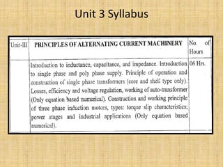
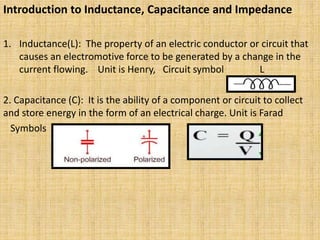
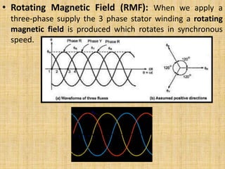
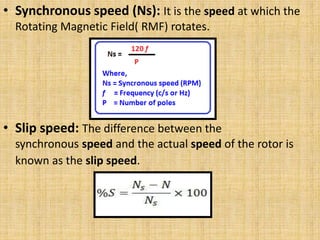
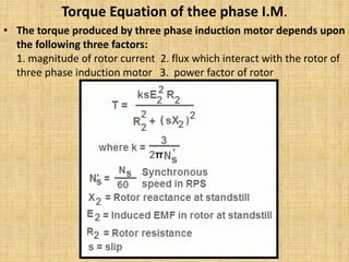
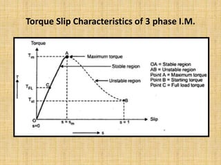
Unit 3
Principles of Alternating current
machinery
by
P. V. Thokal
Assistant Professor
Sanjivani College of Engineering, Kopargaon
Unit 3 Syllabus
Introduction to Inductance, Capacitance and Impedance
1. Inductance(L): The property of an electric conductor or circuit that
causes an electromotive force to be generated by a change in the
current flowing. Unit is Henry, Circuit symbol L
2. Capacitance (C): It is the ability of a component or circuit to collect
and store energy in the form of an electrical charge. Unit is Farad
Symbols
3. Impedance(Z): It is the effective resistance of
an electric circuit or component to alternating
current, arising from the combined effects of
ohmic resistance and reactance. Unit is Ohm.
Z= V/I
Identify the Components
Introduction Single and Poly Phase supply
1. Alternator: Alternator is an electrical machine
which generates AC supply. it is also called as
AC GENERATOR.
Types of Alternators:
1. Single Phase Alternator:
• Generates 1 phase supply
2. 3 Phase Alternator:
• Generates 3 ph. Supply
Benefits of 3 phase system
• Its possible to take single phase supply
From 3 phase supply.
• 3 phase machines are self start machines,
Single phase machines are NOT self start.
• 3 phase machines have higher power factor.
• 3 phase machines have higher efficiency.
• Three phase motors have uniform torque ,
Single phase motors have pulsating torque.
• The output of 3 phase machine is always greater than single phase
machine of same size.
Single Phase Transformer
• TRANSFORMER = TRANSFORM + POWER
• Definition: A transformer can be defined as a static device which
helps in the transformation of electric power in one circuit to electric
power of the same frequency in another circuit.
• Working Principle: it works on the Principle of mutual induction,
according to Faraday’s laws of Electromagnetic Induction.
• Construction: i) Iron Core ii) Windings (Copper or Al)
• Circuit Symbols:
• Types of single phase Transformer (According to
Construction)
1. Core Type Transformer 2. Shell Type Transformer
Images of 1 phase & 3 Phase Transformer
Difference between Core and Shell Type transformer
EMF equation of a single phase transformer
• Transformation Ratio (K):
• Losses in Transformer:
• The Equation for Hysteresis loss is given as:
Ph = η * Bmax
n * f * V
Where Ph = hysteresis loss (W)
η = Steinmetz hysteresis coefficient, depending on
material (J/m3)
Bmax = maximum flux density (Wb/m2)
n = Steinmetz exponent, ranges from 1.5 to 2.5,
depending on material
f = frequency of magnetic reversals per second (Hz)
V = volume of magnetic material (m3)
• The Equation for Eddy current loss is
given as:
Pe = Ke * Bmax
2 * f2 * t2 * V
Pe = eddy current loss (W)
Ke = eddy current constant
B = flux density (Wb/m2)
f = frequency of magnetic reversals per
second (Hz)
t = material thickness (m)
V = volume (m3)
• Rating of a transformer: Transformer rating is
expressed in VA or KVA or MVA
• From KVA rating of transformer we can calculate
primary and secondary current at full load.
KVA rating = V1I1/1000 from this we can write
• I1 = KVAX1000/V1
• I2= KVAX1000/V2
• Why transformer ratings are expressed in
VA/KVA/MVA???
• Efficiency of a Transformer
• Regulation of a transformer
• Auto Transformer:
Advantages:
1. Saving of Copper due to only one Winding.
2. Small in size
3. Higher efficiency than two winding
transformer
4. Better Voltage Regulation
Disadvantages:
• Not useful for HIGH VOLTAGE applications,
due to no isolation between Primary and
Secondary windings.
Applications of Auto Transformers
• Compensating voltage drops by boosting supply
voltage in distribution systems.
• Auto transformers with a number of tapping are
used for starting induction and synchronous
motors.
• Auto transformer is used as variac in laboratory or
where continuous variable over broad ranges are
required.
• Used as Dimmerstat.
Comparison between Autotransformer and Two winding transformer
Three Phase Induction Motor
Construction:
• Stator: Outer Body
• Rotor: Rotating Part
• Types:
1. Squirrel Cage Rotor
2. Slip ring (Wound) Rotor
• Rotating Magnetic Field (RMF): When we apply a
three-phase supply the 3 phase stator winding a rotating
magnetic field is produced which rotates in synchronous
speed.
• Synchronous speed (Ns): It is the speed at which the
Rotating Magnetic Field( RMF) rotates.
• Slip speed: The difference between the
synchronous speed and the actual speed of the rotor is
known as the slip speed.
Torque Equation of thee phase I.M.
• The torque produced by three phase induction motor depends upon
the following three factors:
1. magnitude of rotor current 2. flux which interact with the rotor of
three phase induction motor 3. power factor of rotor
Torque Slip Characteristics of 3 phase I.M.
Power Stages of 3 Phase I.M.
Applications of Squirrel cage and Slip Ring I.M.
• Squirrel cage IM is constant speed motor with
Moderate torque…
Applications: ????????
• Slip Ring IM has high starting torque and
variable speed
Applications: ????????
Thank You

AC Machines

  • 1.
    Unit 3 Principles ofAlternating current machinery by P. V. Thokal Assistant Professor Sanjivani College of Engineering, Kopargaon
  • 2.
  • 3.
    Introduction to Inductance,Capacitance and Impedance 1. Inductance(L): The property of an electric conductor or circuit that causes an electromotive force to be generated by a change in the current flowing. Unit is Henry, Circuit symbol L 2. Capacitance (C): It is the ability of a component or circuit to collect and store energy in the form of an electrical charge. Unit is Farad Symbols
  • 4.
    3. Impedance(Z): Itis the effective resistance of an electric circuit or component to alternating current, arising from the combined effects of ohmic resistance and reactance. Unit is Ohm. Z= V/I
  • 5.
  • 6.
    Introduction Single andPoly Phase supply 1. Alternator: Alternator is an electrical machine which generates AC supply. it is also called as AC GENERATOR. Types of Alternators: 1. Single Phase Alternator: • Generates 1 phase supply 2. 3 Phase Alternator: • Generates 3 ph. Supply
  • 7.
    Benefits of 3phase system • Its possible to take single phase supply From 3 phase supply. • 3 phase machines are self start machines, Single phase machines are NOT self start. • 3 phase machines have higher power factor. • 3 phase machines have higher efficiency. • Three phase motors have uniform torque , Single phase motors have pulsating torque. • The output of 3 phase machine is always greater than single phase machine of same size.
  • 8.
    Single Phase Transformer •TRANSFORMER = TRANSFORM + POWER • Definition: A transformer can be defined as a static device which helps in the transformation of electric power in one circuit to electric power of the same frequency in another circuit. • Working Principle: it works on the Principle of mutual induction, according to Faraday’s laws of Electromagnetic Induction. • Construction: i) Iron Core ii) Windings (Copper or Al)
  • 9.
    • Circuit Symbols: •Types of single phase Transformer (According to Construction) 1. Core Type Transformer 2. Shell Type Transformer
  • 10.
    Images of 1phase & 3 Phase Transformer
  • 11.
    Difference between Coreand Shell Type transformer
  • 12.
    EMF equation ofa single phase transformer
  • 13.
    • Transformation Ratio(K): • Losses in Transformer:
  • 14.
    • The Equationfor Hysteresis loss is given as: Ph = η * Bmax n * f * V Where Ph = hysteresis loss (W) η = Steinmetz hysteresis coefficient, depending on material (J/m3) Bmax = maximum flux density (Wb/m2) n = Steinmetz exponent, ranges from 1.5 to 2.5, depending on material f = frequency of magnetic reversals per second (Hz) V = volume of magnetic material (m3)
  • 15.
    • The Equationfor Eddy current loss is given as: Pe = Ke * Bmax 2 * f2 * t2 * V Pe = eddy current loss (W) Ke = eddy current constant B = flux density (Wb/m2) f = frequency of magnetic reversals per second (Hz) t = material thickness (m) V = volume (m3)
  • 16.
    • Rating ofa transformer: Transformer rating is expressed in VA or KVA or MVA • From KVA rating of transformer we can calculate primary and secondary current at full load. KVA rating = V1I1/1000 from this we can write • I1 = KVAX1000/V1 • I2= KVAX1000/V2 • Why transformer ratings are expressed in VA/KVA/MVA???
  • 17.
    • Efficiency ofa Transformer • Regulation of a transformer
  • 18.
  • 19.
    Advantages: 1. Saving ofCopper due to only one Winding. 2. Small in size 3. Higher efficiency than two winding transformer 4. Better Voltage Regulation Disadvantages: • Not useful for HIGH VOLTAGE applications, due to no isolation between Primary and Secondary windings.
  • 20.
    Applications of AutoTransformers • Compensating voltage drops by boosting supply voltage in distribution systems. • Auto transformers with a number of tapping are used for starting induction and synchronous motors. • Auto transformer is used as variac in laboratory or where continuous variable over broad ranges are required. • Used as Dimmerstat.
  • 21.
    Comparison between Autotransformerand Two winding transformer
  • 22.
    Three Phase InductionMotor Construction: • Stator: Outer Body
  • 23.
    • Rotor: RotatingPart • Types: 1. Squirrel Cage Rotor 2. Slip ring (Wound) Rotor
  • 24.
    • Rotating MagneticField (RMF): When we apply a three-phase supply the 3 phase stator winding a rotating magnetic field is produced which rotates in synchronous speed.
  • 25.
    • Synchronous speed(Ns): It is the speed at which the Rotating Magnetic Field( RMF) rotates. • Slip speed: The difference between the synchronous speed and the actual speed of the rotor is known as the slip speed.
  • 26.
    Torque Equation ofthee phase I.M. • The torque produced by three phase induction motor depends upon the following three factors: 1. magnitude of rotor current 2. flux which interact with the rotor of three phase induction motor 3. power factor of rotor
  • 27.
  • 28.
    Power Stages of3 Phase I.M.
  • 29.
    Applications of Squirrelcage and Slip Ring I.M. • Squirrel cage IM is constant speed motor with Moderate torque… Applications: ???????? • Slip Ring IM has high starting torque and variable speed Applications: ????????
  • 30.