Download to read offline


![Determination of Transformer Eq. cct.
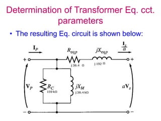
parameters
• Input current, input voltage & input power measured
• From these can determine p.f., input current, and
consequently both magnitude & angle of excitation
impedance (RC, and XM)
• First determining related admittance and
Susceptance:
GC=1/RC & BM=1/XM YE=GC-jBM=1/RC -1/XM
• Magnitude of excitation admittance referred to primary
circuit : |YE |=IOC/VOC
• P.f. used to determine angle,
• PF=cosθ=POC/[VOC . IOC]
• θ=cos‾1 {POC/[VOC . IOC]}](https://image.slidesharecdn.com/25471energyconversion5-240130093918-fe9496f2/85/ENERGY_CONVERSION-5_-ppt-12-320.jpg)


![Determination of Transformer Eq.
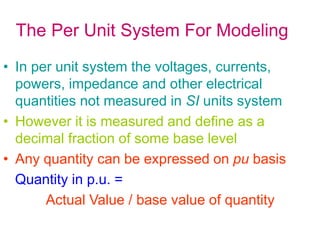
cct. parameters
• The input voltage, current and power are again measured
• Since input voltage is so low during short-circuited test, negligible current
flows through excitation branch
• Therefore, voltage drop in transformer attributed to series elements
• Magnitude of series impedances referred to primary side of transformer is:
|ZSE| = VSC/ ISC , PF=cosθ=PSC/[VSC ISC]
• θ=cos‾1 {PSC/[VSC ISC]}
• ZSE= VSC / ISC = VSC/ ISC
• series impedance ZSE is equal to:
• ZSE=Req+jXeq = (RP+ a²RS) + j(XP+a²XS)
• It is possible to determine the total series impedance referred to primary side
, however difficult to split series impedance into primary & secondary
components although it is not necessary to solve problem
• These same tests may also be performed on secondary side of transformer
0
](https://image.slidesharecdn.com/25471energyconversion5-240130093918-fe9496f2/85/ENERGY_CONVERSION-5_-ppt-15-320.jpg)
![Determination of Transformer Eq.
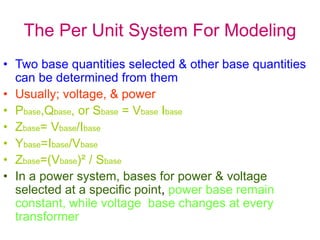
cct. parameters
• Determine Equivalent cct.
Impedances of a 20 kVA,
8000/240 V, 60 Hz
transformer
• O.C. & S.C. measurements
shown
• P.F. in O.C. is:
• PF=cosθ=POC/[VOCIOC]=
400 W/ [8000V x 0.214A]
=0.234 lagging
O.C. test
(on primary)
S.C. test
(on primary)
VOC=8000V VSC=489V
IOC=0.214A ISC=2.5 A
POC=400W PSC=240W](https://image.slidesharecdn.com/25471energyconversion5-240130093918-fe9496f2/85/ENERGY_CONVERSION-5_-ppt-16-320.jpg)

![Determination of Transformer Eq.
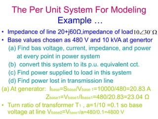
cct. parameters
• PF in sc test:
PF=cosθ = PSC/[VSCISC]=240W/ [489x2.5]=0.196 lagging
• Series impedance:
ZSE=VSC/ISC
= 489 V/ 2.5 A =195.6
=38.4 +j 192 Ω
• The Eq. resistance & reactance are :
• Req=38.4 Ω , Xeq=192 Ω
PF
1
cos
7
.
78
7
.
78
](https://image.slidesharecdn.com/25471energyconversion5-240130093918-fe9496f2/85/ENERGY_CONVERSION-5_-ppt-18-320.jpg)


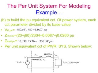

The document discusses the equivalent circuit model of a transformer. 1) The equivalent circuit accounts for copper losses in the primary and secondary windings, eddy current losses in the core, hysteresis losses in the core, and leakage fluxes between the primary and secondary coils. 2) Key components of the equivalent circuit model include resistances to represent copper losses, inductances to represent the effects of mutual and leakage fluxes, and a resistance and inductance in parallel to represent core losses and excitation. 3) Test procedures for determining the parameters of the equivalent circuit model are described, including open circuit and short circuit tests to calculate resistance, reactance, and impedance values.


![[LECTURE - 01 & 02] Equivalent Circuit P](https://cdn.slidesharecdn.com/ss_thumbnails/lec-0102equivalentcircuit-241104145204-d52809f3-thumbnail.jpg?width=640&height=640&fit=bounds)


