Downloaded 354 times
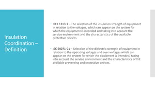
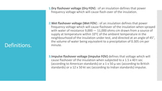
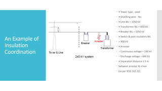


The document outlines insulation coordination, which is the process of selecting appropriate insulation levels for electrical system components to minimize failures. It defines various types of flashover voltages, describes requirements for insulation regarding power frequencies and overvoltage events, and details methods for insulation coordination studies. Additionally, it covers aspects such as line insulation determination, selection of equipment insulation levels, and data needed for insulation coordination studies.


