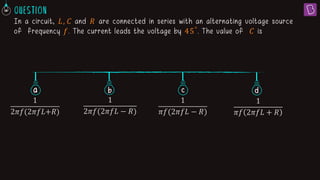
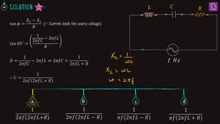
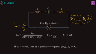
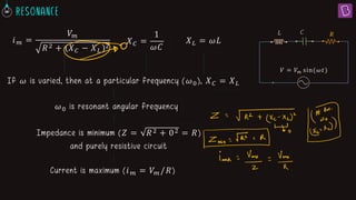
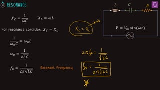
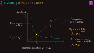
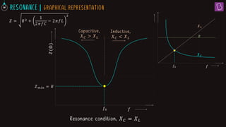
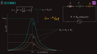
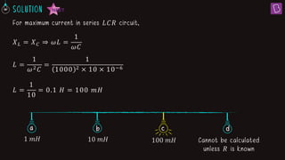
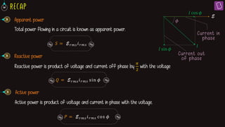
1. In a series LCR circuit at resonance, the impedances of the inductor (XL) and capacitor (XC) are equal. This results in the lowest overall impedance (Z = R) and maximum current.
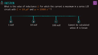
2. For a series LCR circuit with C = 10 μF operating at 1000 s-1, the inductance L that produces resonance and maximum current is 100 mH.
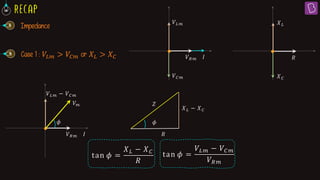
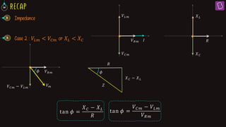
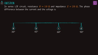
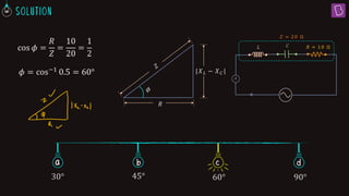
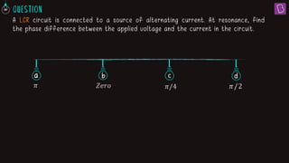
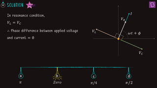
3. At resonance in a series LCR circuit, the phase difference between the applied voltage and current is zero since the voltage drops across the inductor and capacitor are equal.

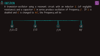
![Series L-C-R circuit 𝑅
𝑉 = 𝑉𝑚 sin(𝜔𝑡)
𝐶
𝐿
𝐼 = 𝐼𝑚 sin(𝜔𝑡 + 𝜙)
𝐼
𝑉𝑅
𝜔𝑡 + 𝜙
𝑉𝐿
𝑉𝐶
𝑉𝑅
𝑉𝐶𝑚 − 𝑉𝐿𝑚
𝜙
𝜔𝑡
𝑉
𝑉𝑚
2 = 𝑉𝑅𝑚
2
+ 𝑉𝐶𝑚 − 𝑉𝐿𝑚
2
𝑉𝑚
2 = 𝐼𝑚 𝑅 2 + 𝐼𝑚 𝑋𝐶 − 𝐼𝑚 𝑋𝐿
2
𝑉𝑚
2 = 𝐼𝑚
2 [𝑅2 + 𝑋𝐶 − 𝑋𝐿
2]
𝐼𝑚 =
𝑉𝑚
𝑅2 + 𝑋𝐶 − 𝑋𝐿
2
𝑉𝐶 + 𝑉𝐿
𝑉𝑅𝑚](https://image.slidesharecdn.com/resonance-240101135029-53b890be/85/Resonance-pdf-4-320.jpg)