Downloaded 86 times
![For the sake of simplifying the process of finding the response we shall also assume
that the initial current in the inductor and the voltage across the capacitor are zero.
Then applying the Kirchhoff’s current law (KCL )( i = iC +iL ) to the common node we
get the following differential equation:
(V-v) /R = 1/L dt’ + C. dv/dt
where v = vC(t) = vL(t) is the variable whose value is to be obtained. When we
differentiate both sides of the above equation once with respect to time we get the
standard Linear second-order homogeneous differential equation
C. (d 2
v / dt 2
) + (1/R) ( dv/dt) + (1/L).v =0
(d 2
v / dt 2
) + (1/RC) ( dv/dt) + (1/LC).v =0
whose solution v(t) is the desired response.
This can be written in the form:
[s 2
+ (1/RC)s + (1/LC)].v(t) = 0 where ‘s’ is an operator equivalent to (d/dt) and the
corresponding characteristic equation is then given by :
[s 2
+ (1/RC)s + (1/LC)] = 0
This equation is usually called the auxiliary equation or the characteristic equation. If
it can be satisfied, then our assumed solution is correct. This is a quadratic equation
and the roots s1 and s2are given as :
s1= − 1/2RC+√[(1/2RC) 2
− 1/LC]
s2= − 1/2RC−√[ (1/2RC)2
− 1/LC ]
Series RLC circuit:](https://image.slidesharecdn.com/bee2-240821031852-ed79a54a/75/MODULE-2-AC-CIRCUITS-REPRESENTATION-OF-SINUSOIDAL-WAVEFORMS-PEAK-RMS-AND-AVERAGE-VALUE-6-2048.jpg)
![Applying KVL to the series RLC circuit shown in the figure above at t= 0 gives the
following basic relation :
V = vR(t) + vC(t ) + vL(t)
Representing the above voltages in terms of the current iin the circuit we get the
following integral differentia lequation:
Ri + 1/C∫ 𝒊𝒅𝒕 + L. (di/dt)= V
To convert it into a differential equation it is differentiated on both sides with respect
to time and we get
L(d2 i/dt2 )+ R(di/dt)+ (1/C)i = 0
This can be written in the form
[s2 + (R/L)s + (1/LC)].i = 0 where ‘s’ is an operator equivalent to (d/dt) And the
corresponding characteristic equation is then given by
[s2 + (R/L)s + (1/LC)] = 0
This is in the standard quadratic equation form and the rootss1ands2are given by
s1,s2 =− R/2L±√[(R/2L)2− (1/LC)]= −α ±√(α 2– ω0 2 )
where α is known as the same exponential damping coefficient and
ω0is known as the same Resonant frequency
as explained in the case of Parallel RLC circuit and are given by :
α = R/2L and ω0= 1/ √LC and A1 and A2must be found by applying the given initial
conditions.](https://image.slidesharecdn.com/bee2-240821031852-ed79a54a/75/MODULE-2-AC-CIRCUITS-REPRESENTATION-OF-SINUSOIDAL-WAVEFORMS-PEAK-RMS-AND-AVERAGE-VALUE-7-2048.jpg)
![Here also we note three basic scenarios with the equations for s1 and s2 depending
on the relative sizes of αand ω0 (dictated by the values of R, L, and C).
CaseA: α > ω0,i.e when (R/2L) 2>1/LC , s1 and s2 will both be negative real
numbers, leading to what is referred to as an over damped response given by : i (t)
= A1e s1t
+ A2e s2t
. Sinces1 and s2 are both be negative real numbers this is the
(algebraic) sum of two decreasing exponential terms. Since s2 is a larger negative
number it decays faster and then the response is dictated by the first term A1e s1t
.
Case B : α = ω0, ,i.e when (R/2L) 2=1/LCs1 and s2are equal which leads to what is
called a critically damped response given by : i (t) = e −αt (A1t + A2) Case
C : α < ω0,i.e when (R/2L) 2
2.3 Phasor Representation, Real Power, Reactive Power, Apparent
Power, Power Factor, Power Triangle
Apparent power : (S):- it is defined as product of rms value of voltage (v) and current (I), or it
is the total power/maximum power
S= V × I
Unit - Volte- Ampere (VA)
In kilo – KVA
2. Real power/ True power/Active power/Useful power : (P) it is defined as the
product of rms value of voltage and current and the active component or it is the
average or actual power consumed by the resistive path (R) in the given
combinational circuit.
It is measured in watts
P = VI Φ watts / KW, where Φ is the power factor angle.
3. Reactive power/Imaginary/useless power [Q]
It is defined as the product of voltage, current and sine B and I
Therefore,
Q= V.I Φ
Unit –V A R](https://image.slidesharecdn.com/bee2-240821031852-ed79a54a/75/MODULE-2-AC-CIRCUITS-REPRESENTATION-OF-SINUSOIDAL-WAVEFORMS-PEAK-RMS-AND-AVERAGE-VALUE-8-2048.jpg)
![XL = - inductive reactance
capacitive reactance
At a particle or frequency f=fr,the inductive and capacitive reactance are exactly
equal
Therefore, XL = XC ----at f=fr
i.e.
Therefore,
and rad/sec
2.4 Analysis Of Single-Phase Ac Circuits Consisting Of R, L, C, Rl,
Rc, Rlc Combinations (Series And Parallel)
3 Basic element of AC circuit.
1] Resistance
2] Inductance
3] Capacitance
Each element produces opposition to the flow of AC supply in forward manner.
Reactance
Inductive Reactance (X
L)
It is opposition to the flow of an AC current offered by inductor.
XL = ω L But ω = 2 ᴫ F
XL = 2 ᴫ F L](https://image.slidesharecdn.com/bee2-240821031852-ed79a54a/75/MODULE-2-AC-CIRCUITS-REPRESENTATION-OF-SINUSOIDAL-WAVEFORMS-PEAK-RMS-AND-AVERAGE-VALUE-10-2048.jpg)
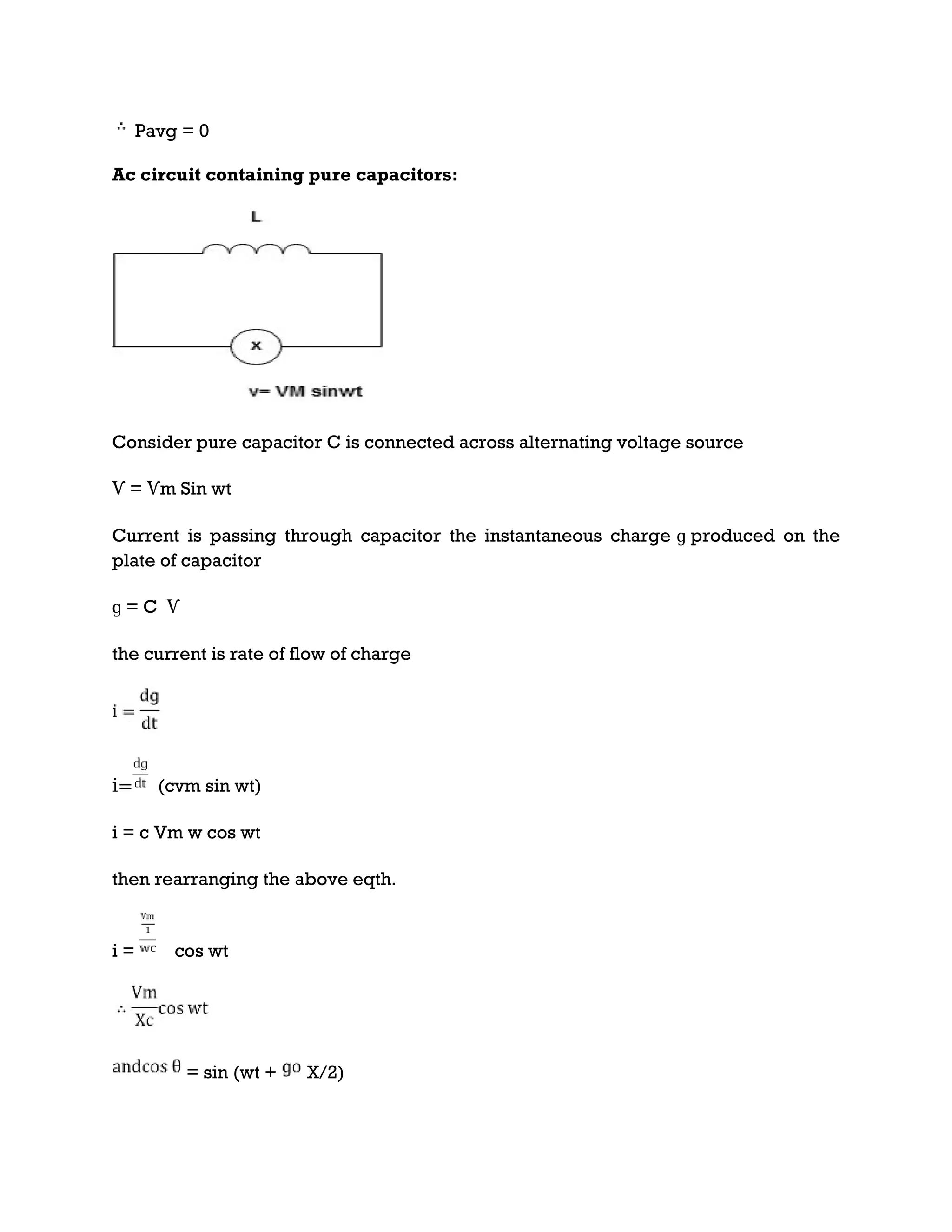
![P = -
Constant fluctuating power if we integrate it becomes zero
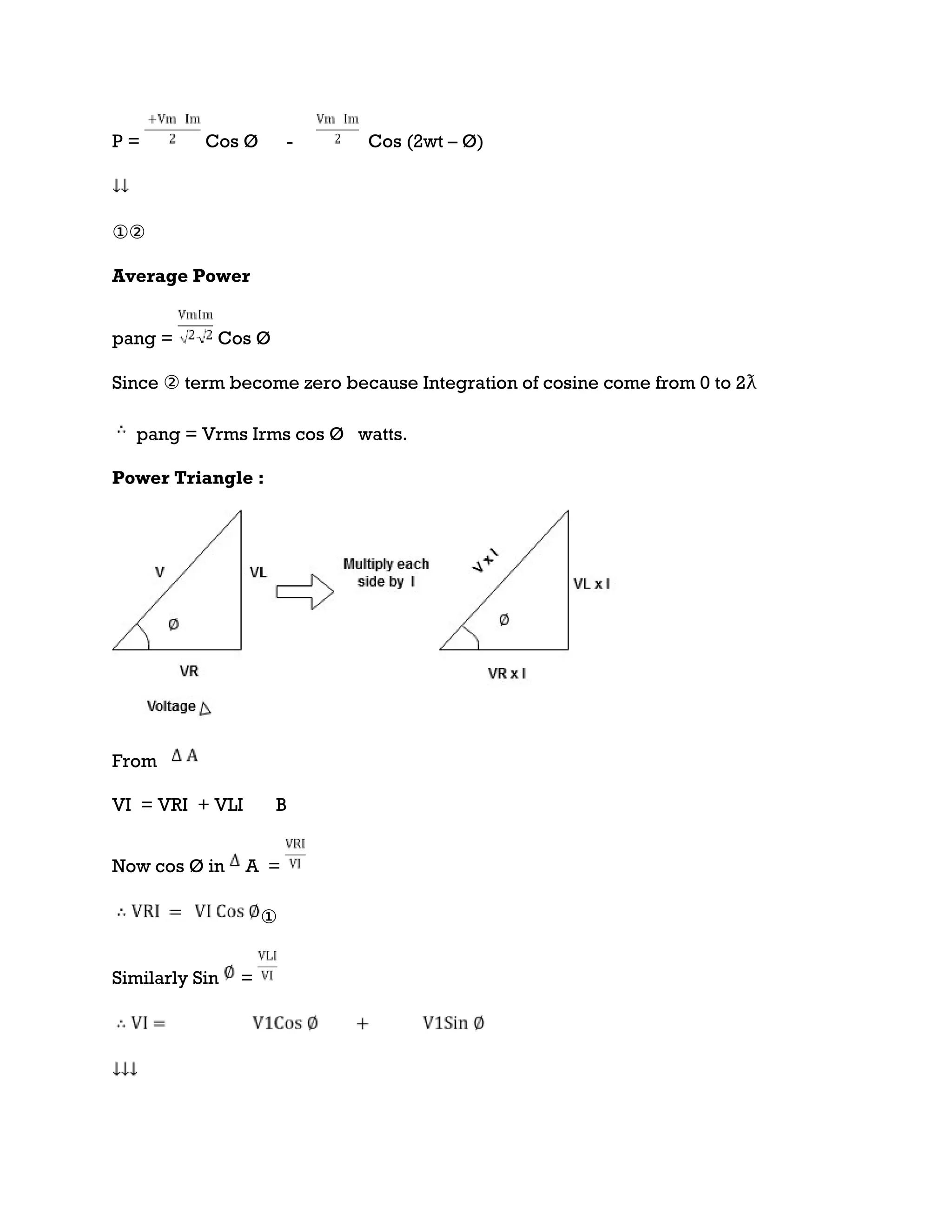
Average power
Pavg = Pavg =
Pavg = Vrms Irms
Power ware form [Resultant]
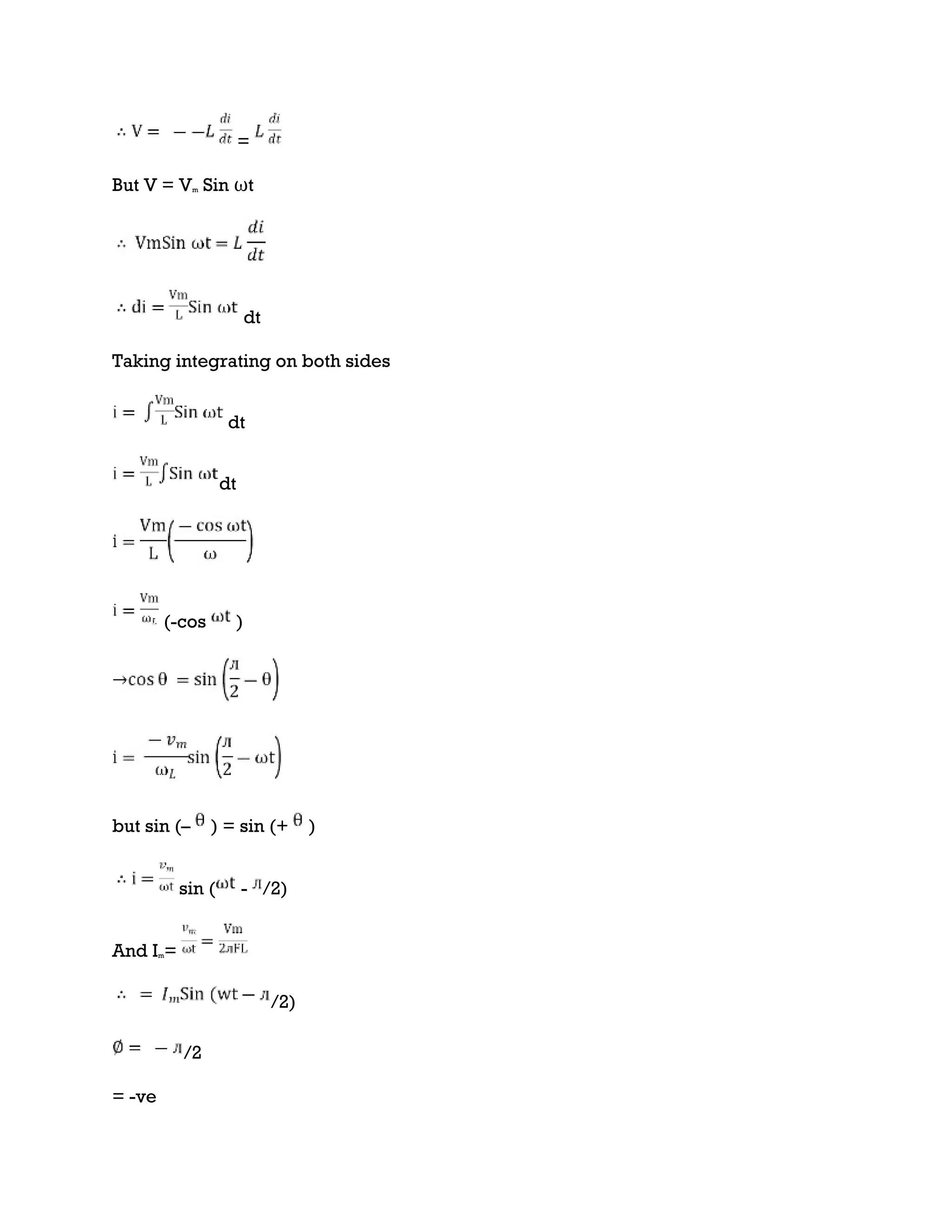
Ac circuit containing pure Inductors
Consider pure
Inductor (L) is
connected across
alternating
voltage. Source
V = Vm Sin ωt
When an
alternating
current flow through inductance it set ups alternating
magnetic flux around the inductor.
This changing the flux links the coil and self-induced emf is produced According to
faradays Law of E M I
e =
at all instant applied voltage V is equal and opposite to self-induced emf [ lenz’s law]
V = -e](https://image.slidesharecdn.com/bee2-240821031852-ed79a54a/75/MODULE-2-AC-CIRCUITS-REPRESENTATION-OF-SINUSOIDAL-WAVEFORMS-PEAK-RMS-AND-AVERAGE-VALUE-13-2048.jpg)
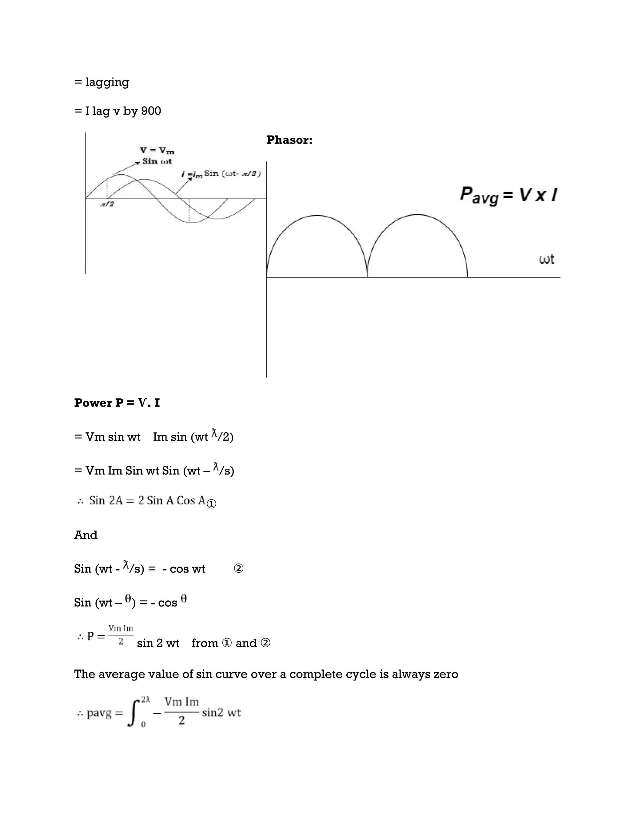
![i = sin (wt + X/2)
but
X/2)
= leading
= I leads V by 900
Waveform:
Phase
Power P= Ѵ. i
= [Vm sinwt] [ Im sin (wt + X/2)]
= Vm Im Sin wt Sin (wt + X/2)]
(cos wt)
to charging power waveform [resultant].](https://image.slidesharecdn.com/bee2-240821031852-ed79a54a/75/MODULE-2-AC-CIRCUITS-REPRESENTATION-OF-SINUSOIDAL-WAVEFORMS-PEAK-RMS-AND-AVERAGE-VALUE-17-2048.jpg)
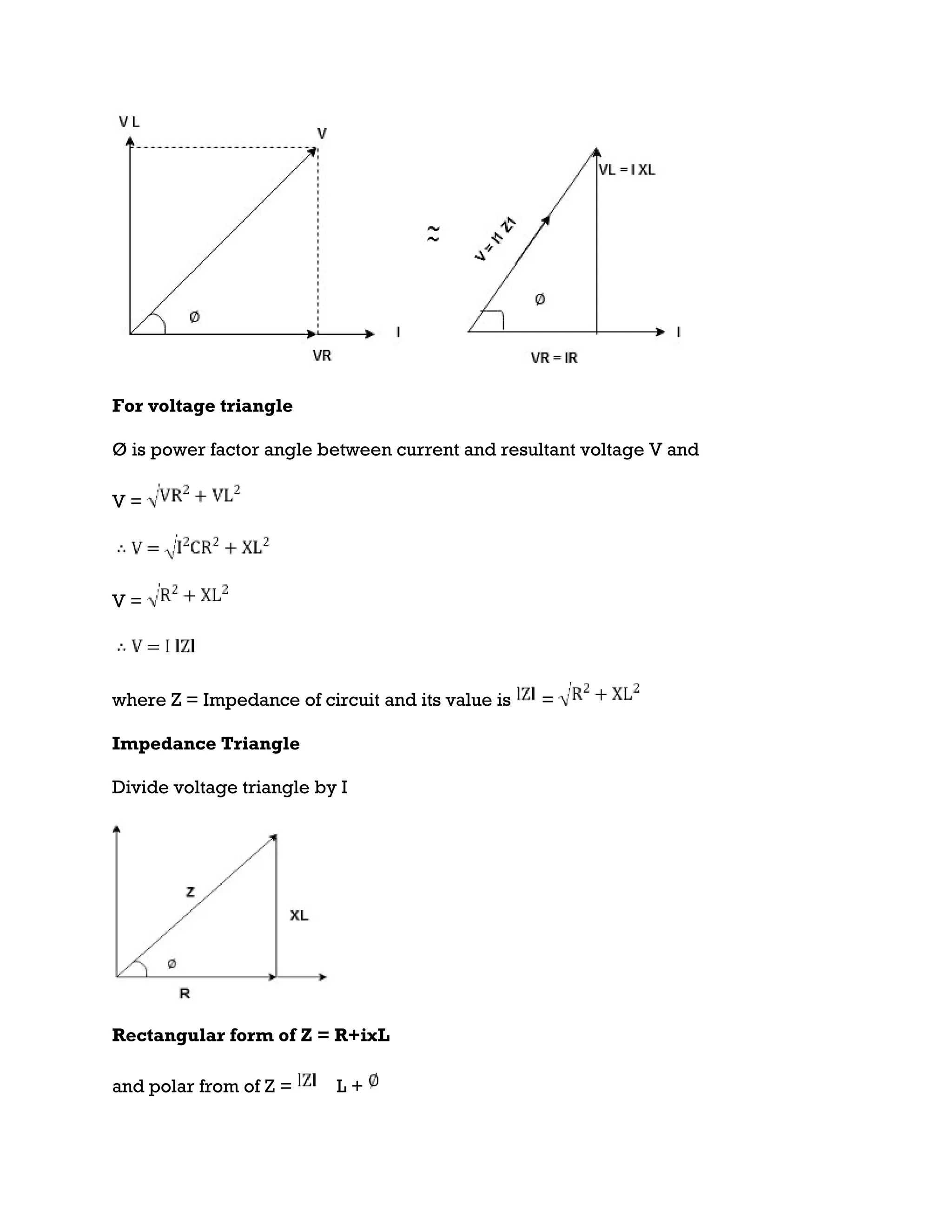
![Series R-L Circuit
Consider a series R-L circuit connected across voltage source V= Vm sin wt
As some I is the current flowing through the resistor and inductor due do this current
voltage drops arcos R and L R VR = IR and L VL = I X L
Total V = VR + VL
V = IR + I X L V = I [R + X L]
Take current as the reference phasor : 1) for resistor current is in phase with voltage
2) for Inductor voltage leads current or current lags voltage by 90 0.](https://image.slidesharecdn.com/bee2-240821031852-ed79a54a/75/MODULE-2-AC-CIRCUITS-REPRESENTATION-OF-SINUSOIDAL-WAVEFORMS-PEAK-RMS-AND-AVERAGE-VALUE-18-2048.jpg)
![Apparent Power Average or true Reactive or useless power
Or real or active
-Unit (VI) Unit (Watts) C/W (VAR) denoted by (Ø)
Denoted by [S] denoted by [P]
Power for R L ekt.
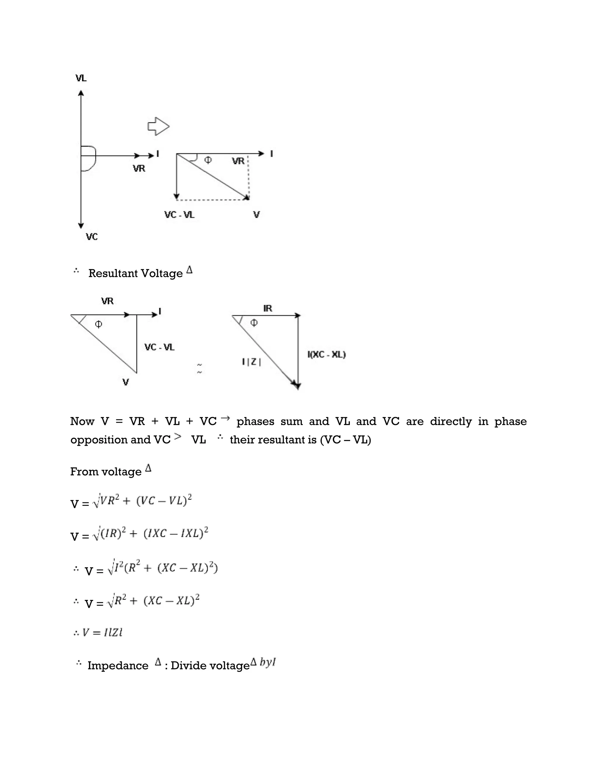
Series R-C circuit
V = Vm sin wt
VR
I](https://image.slidesharecdn.com/bee2-240821031852-ed79a54a/75/MODULE-2-AC-CIRCUITS-REPRESENTATION-OF-SINUSOIDAL-WAVEFORMS-PEAK-RMS-AND-AVERAGE-VALUE-22-2048.jpg)
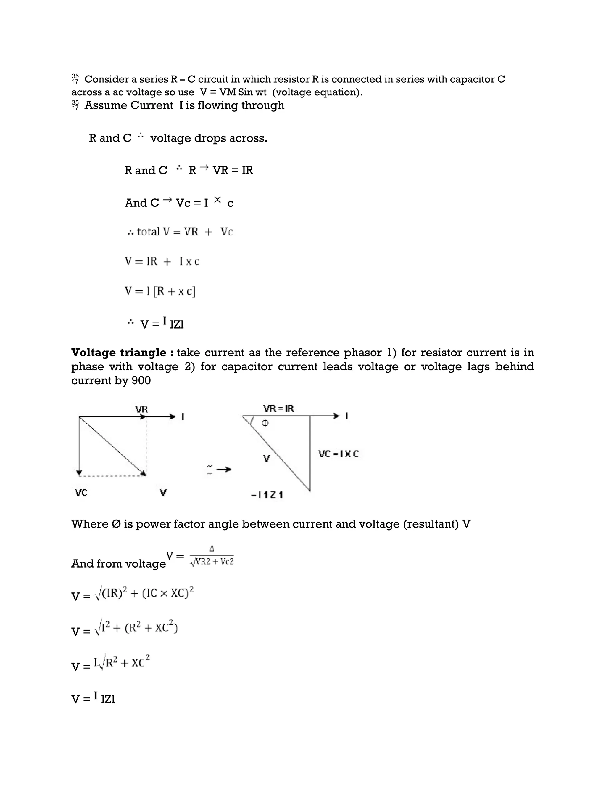
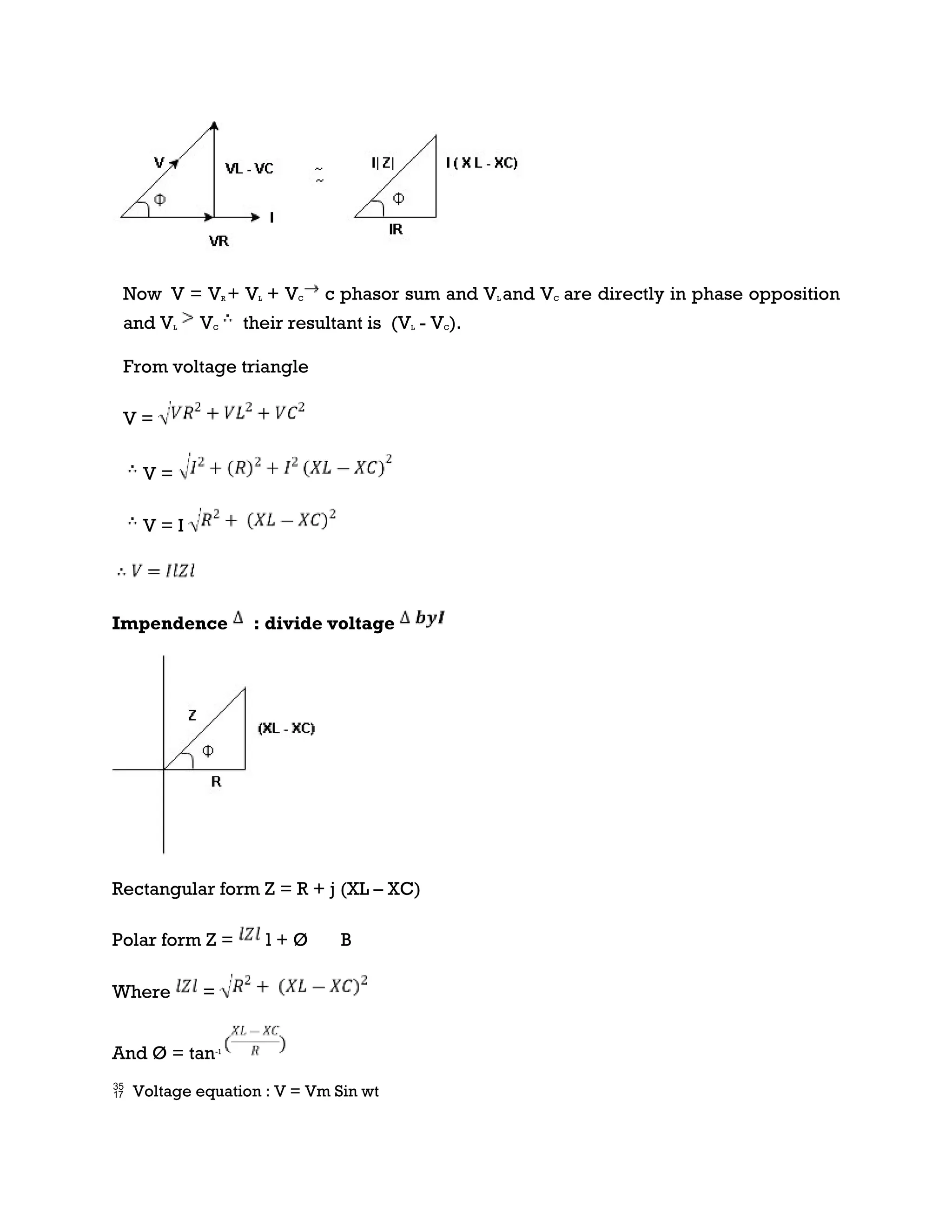
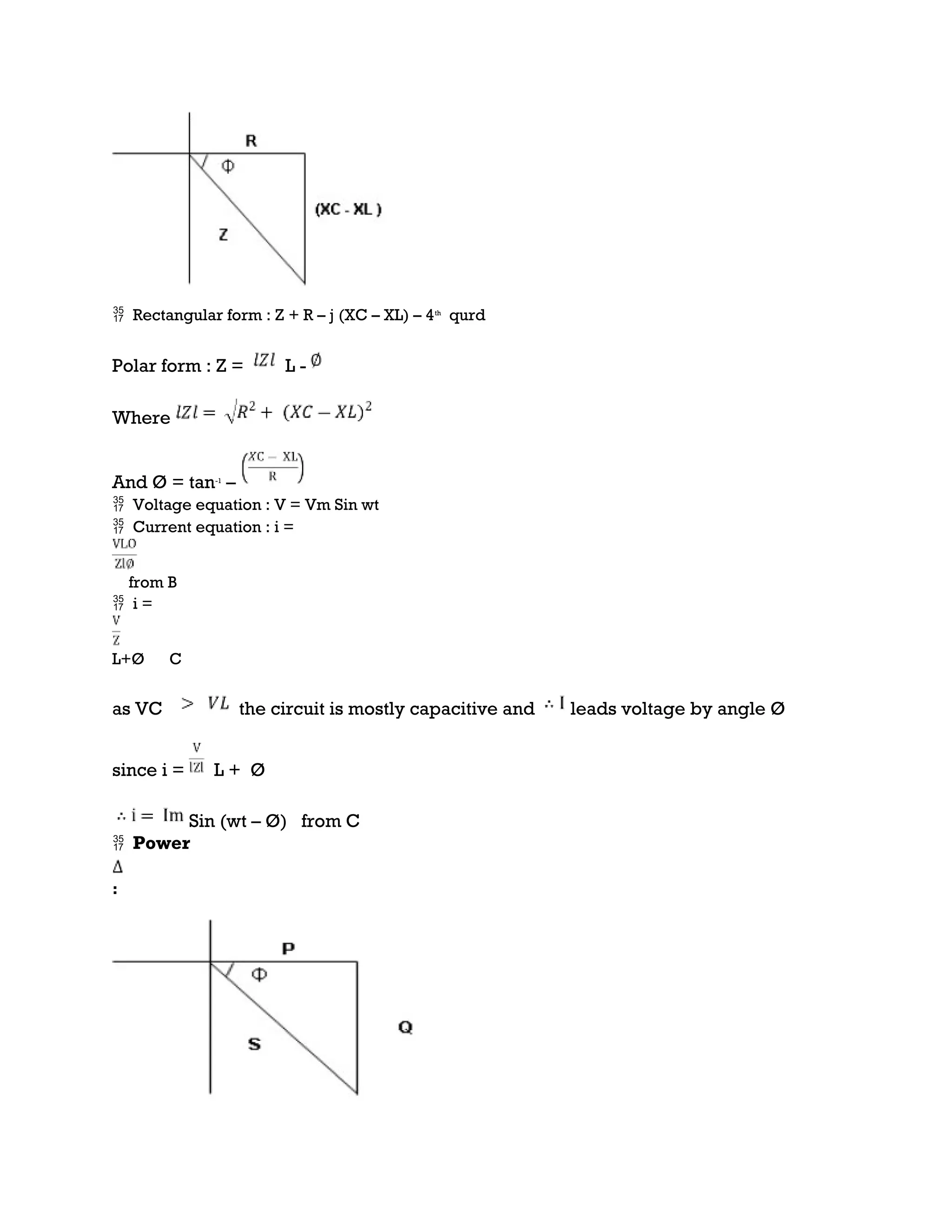
![Where Z = impedance of circuit and its value is lZl =
Impendence triangle :
Divide voltage by as shown
Rectangular from of Z = R - jXc
Polar from of Z = lZl L - Ø
( - Ø and –jXc because it is in fourth quadrant ) where
lZl =
and Ø = tan -1
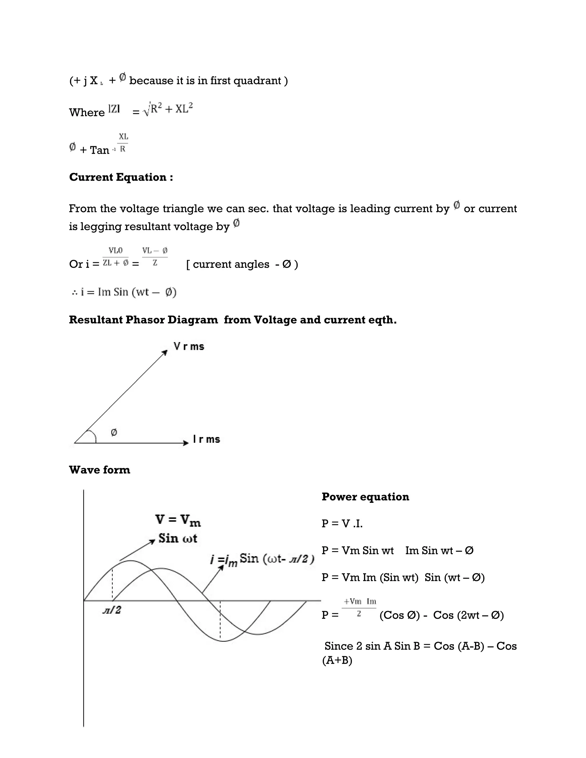
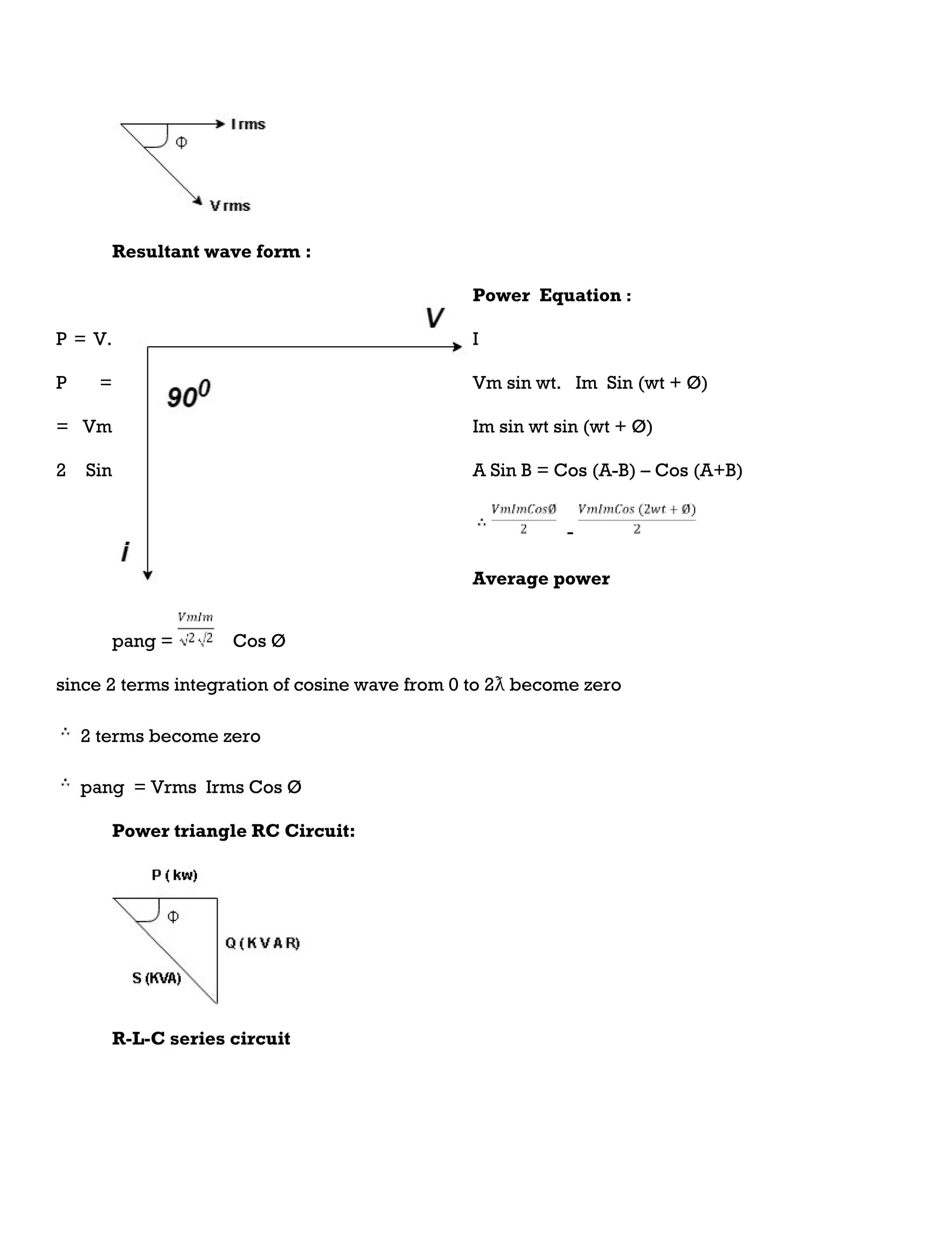
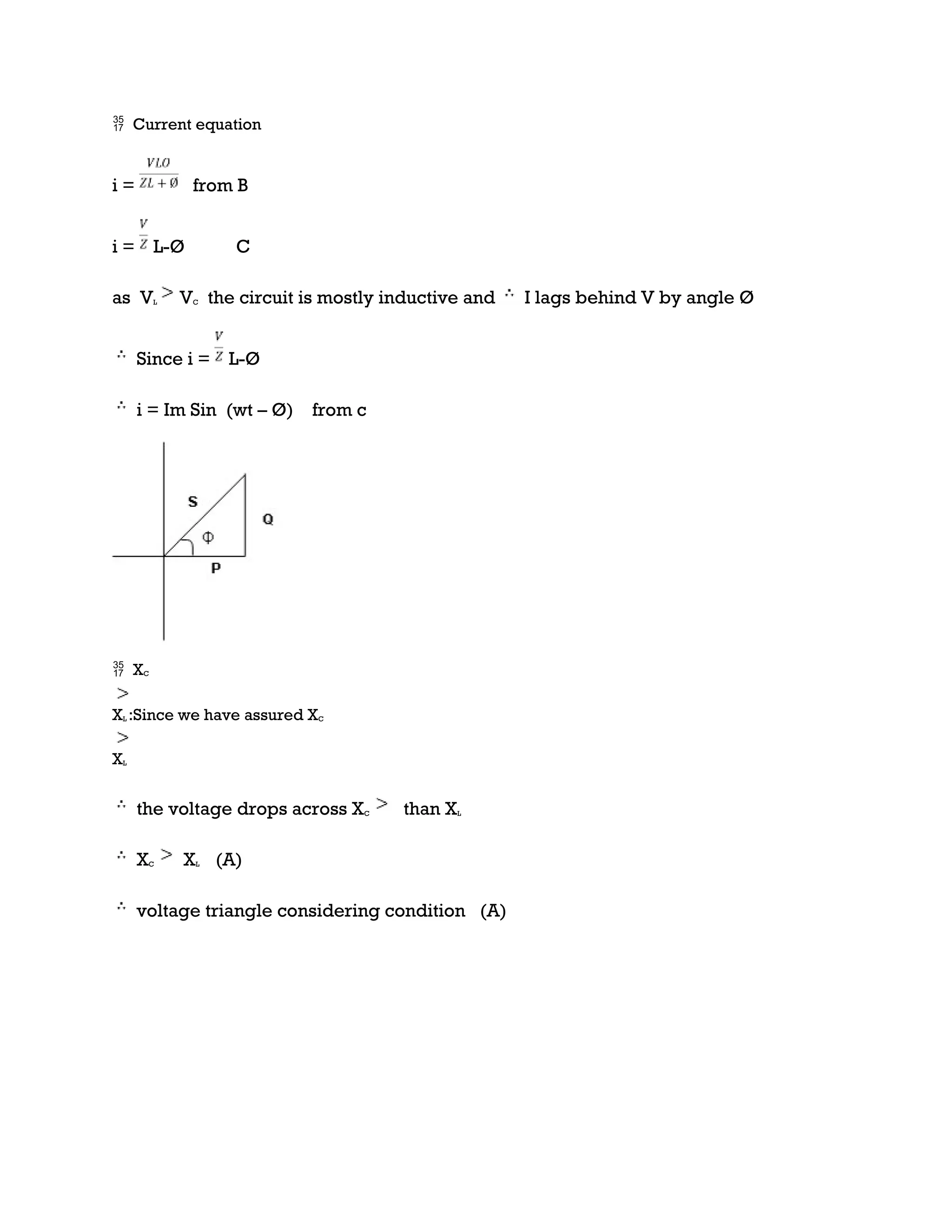
Current equation :
from voltage triangle we can see that voltage is lagging current by Ø or current is leading
voltage by Ø
i = IM Sin (wt + Ø) since Ø is +ve
Or i = for RC
LØ [ resultant current angle is + Ø]
Resultant phasor diagram from voltage and current equation](https://image.slidesharecdn.com/bee2-240821031852-ed79a54a/75/MODULE-2-AC-CIRCUITS-REPRESENTATION-OF-SINUSOIDAL-WAVEFORMS-PEAK-RMS-AND-AVERAGE-VALUE-24-2048.jpg)
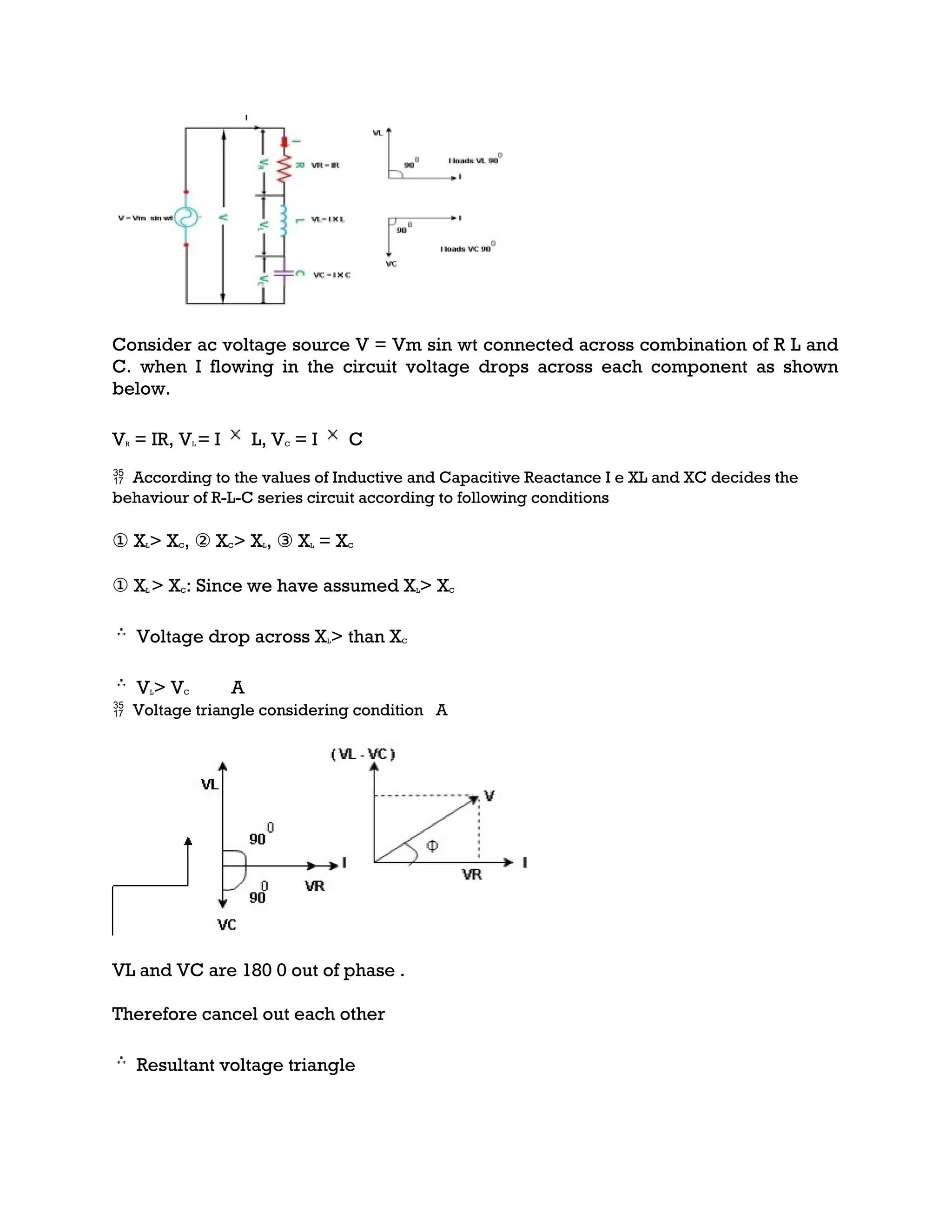

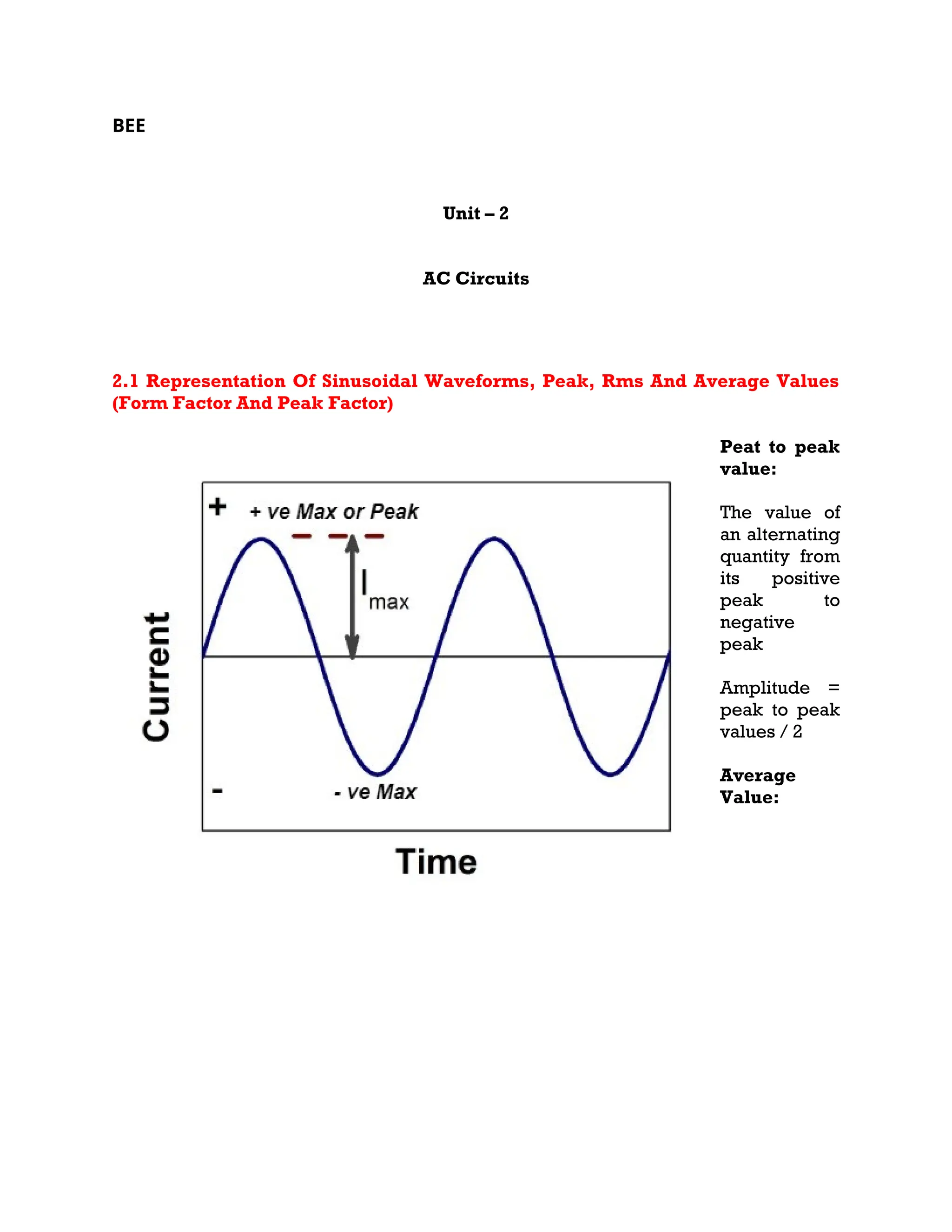
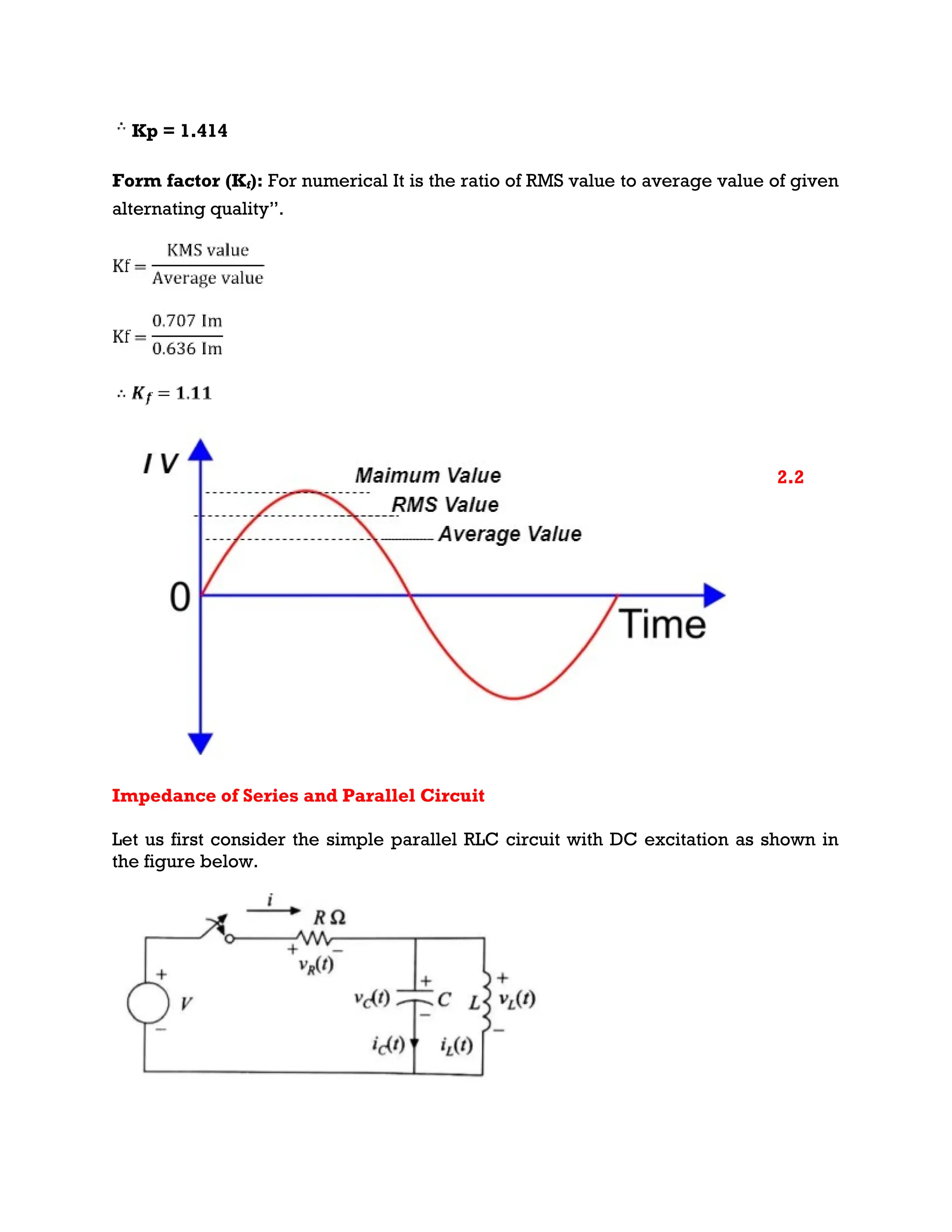
This document discusses the representation and analysis of alternating current (AC) circuits, including the principles of sinusoidal waveforms, peak, RMS, and average values, as well as form factor and peak factor. It covers the impedance of series and parallel circuits, differential equations derived from Kirchhoff's laws, and power components such as real power, reactive power, and power factor in AC systems. The document explains resonance and various configurations in circuits involving resistors, inductors, and capacitors, detailing the relationships and equations governing their behavior.
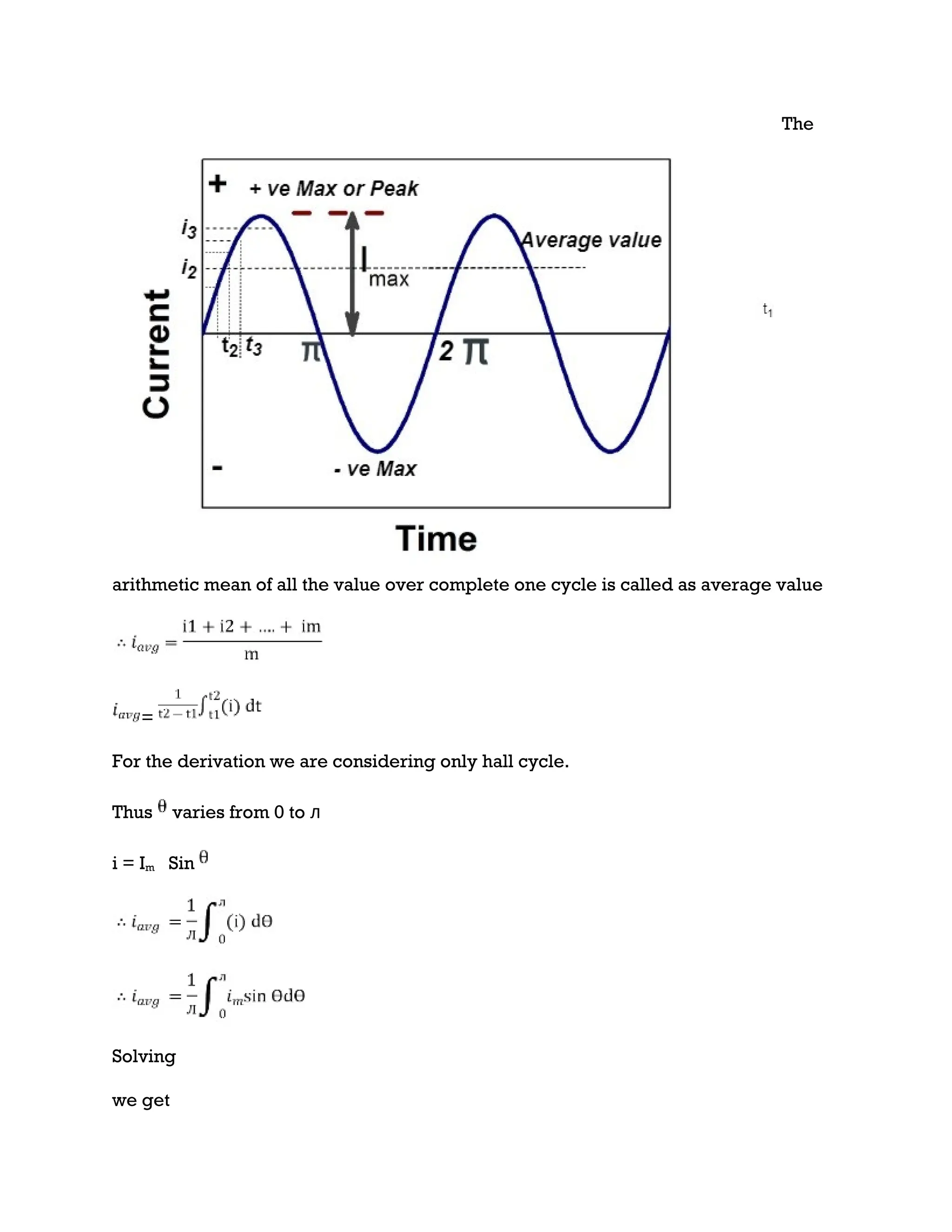
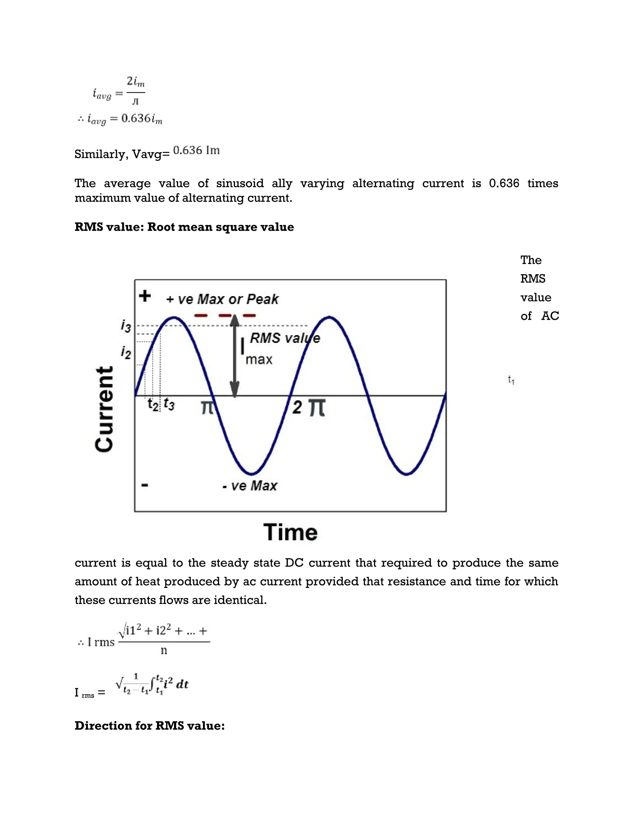
Introduction to AC waveforms, definitions of peak to peak, average, and RMS values, including formulas for average and RMS calculations.
Detailed explanation of impedance in series and parallel RLC circuits, KCL application, differential equations, and analysis of responses.
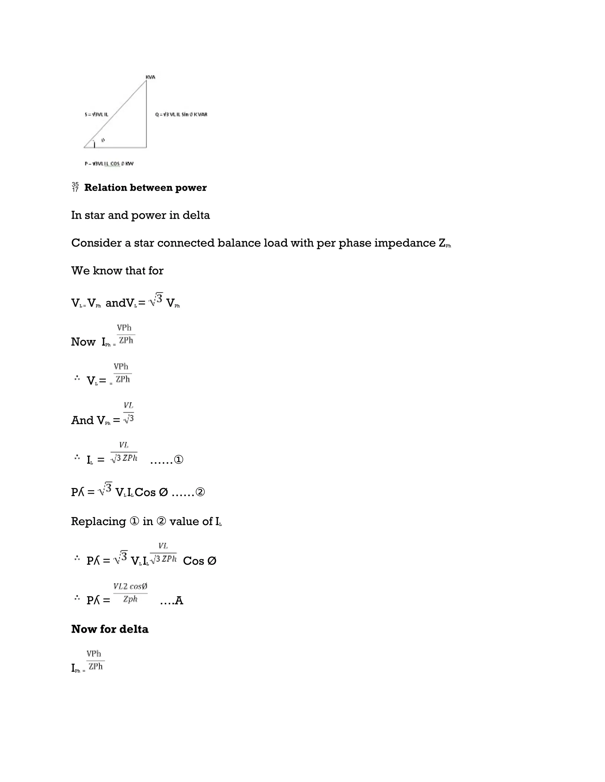
Introduction to real, reactive, and apparent power in AC circuits, explaining power triangles and their relationships.
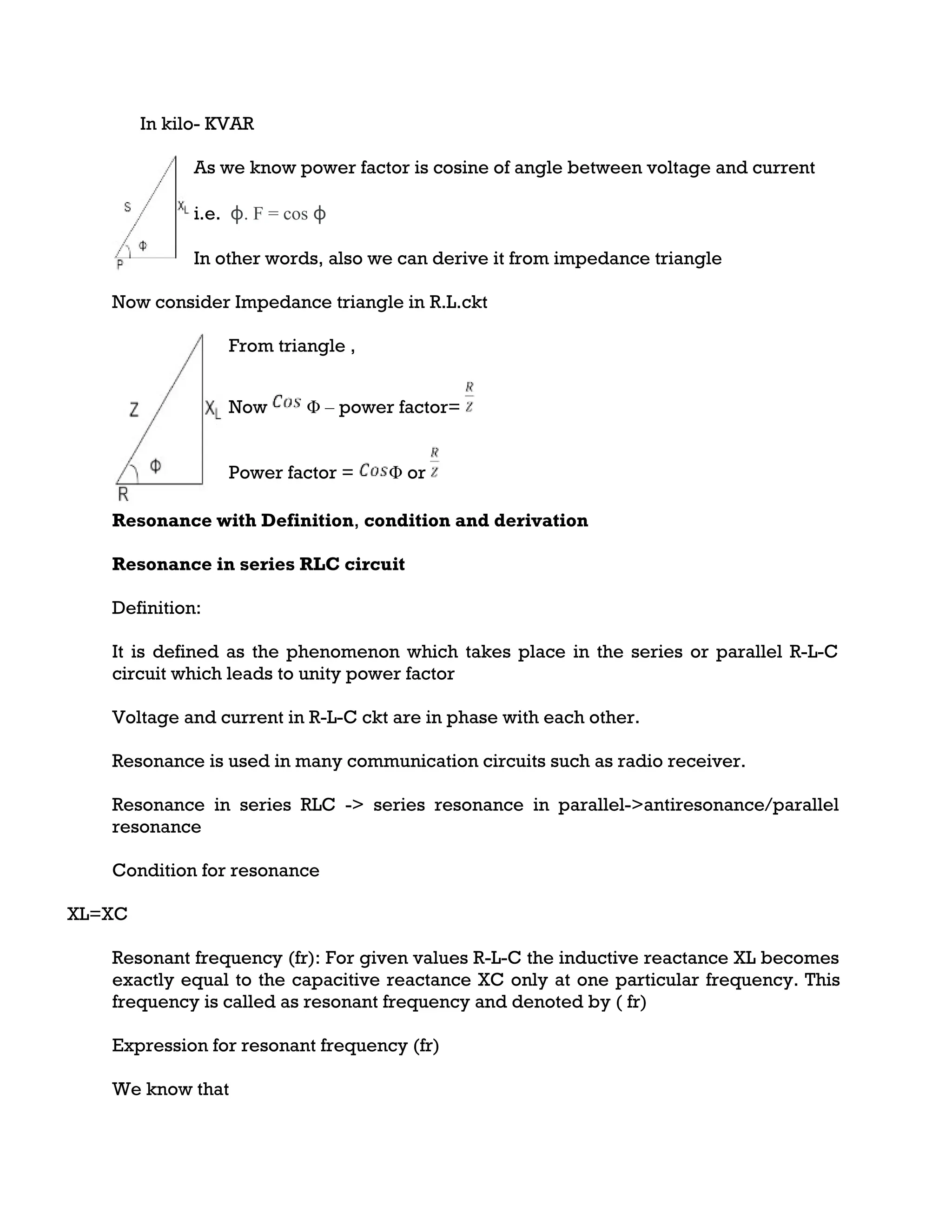
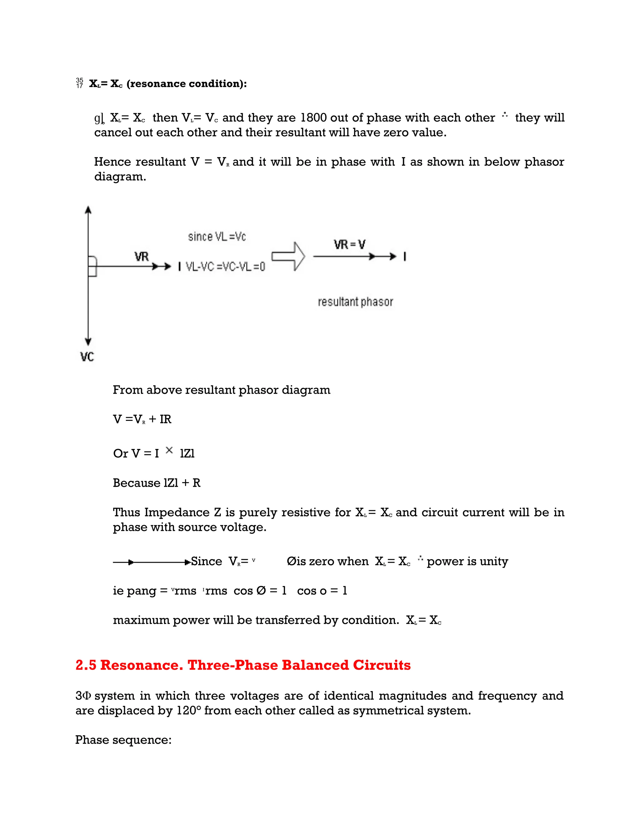
Definition and conditions for resonance in series RLC circuits, including resonant frequency formulation.
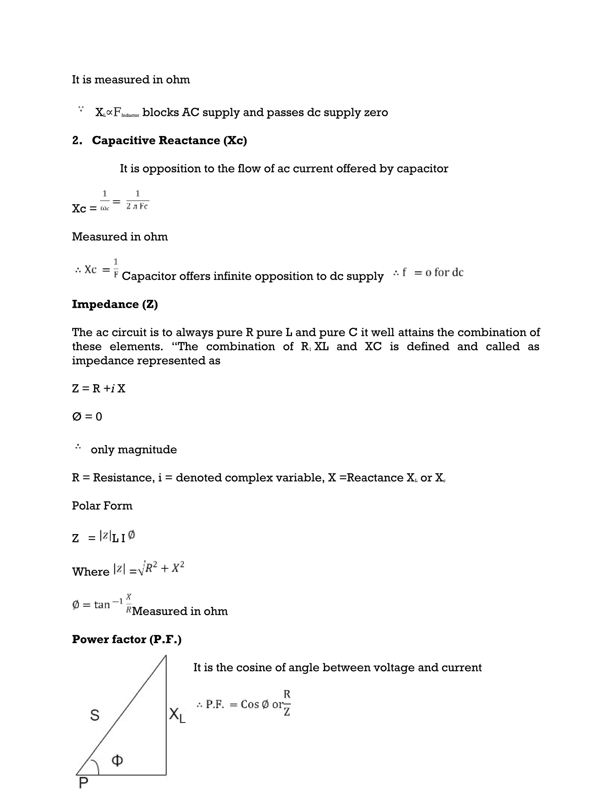
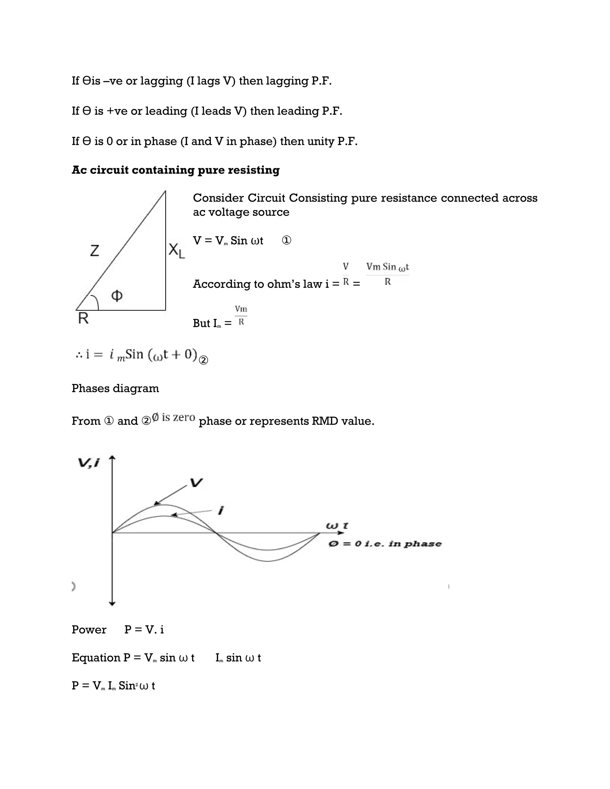
Analysis of various elements in AC circuits such as resistance, inductance, capacitive reactance and their interactions.
Power equations and calculations in series R-L and R-C circuits with diagrams demonstrating average and apparent power.
Analysis of RLC series circuits behavior under resonant conditions along with discussion on balanced three-phase circuits.
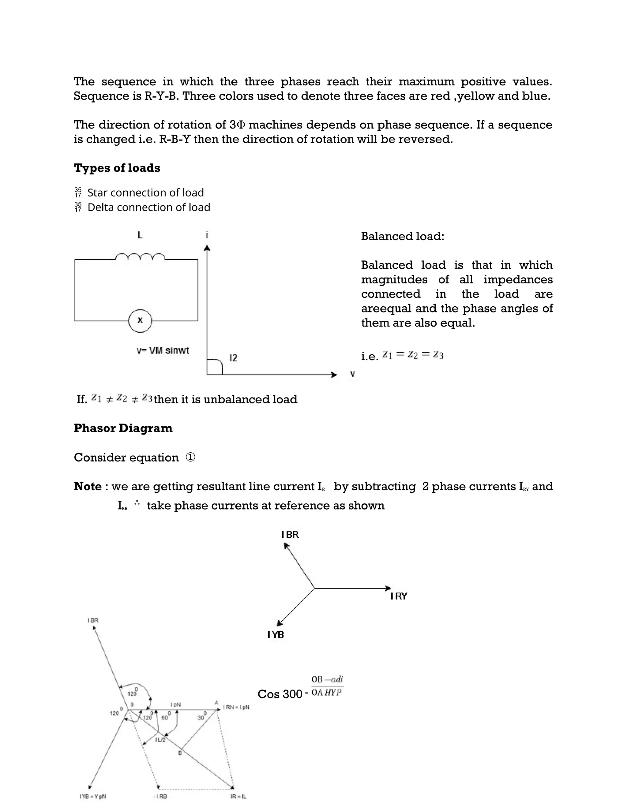
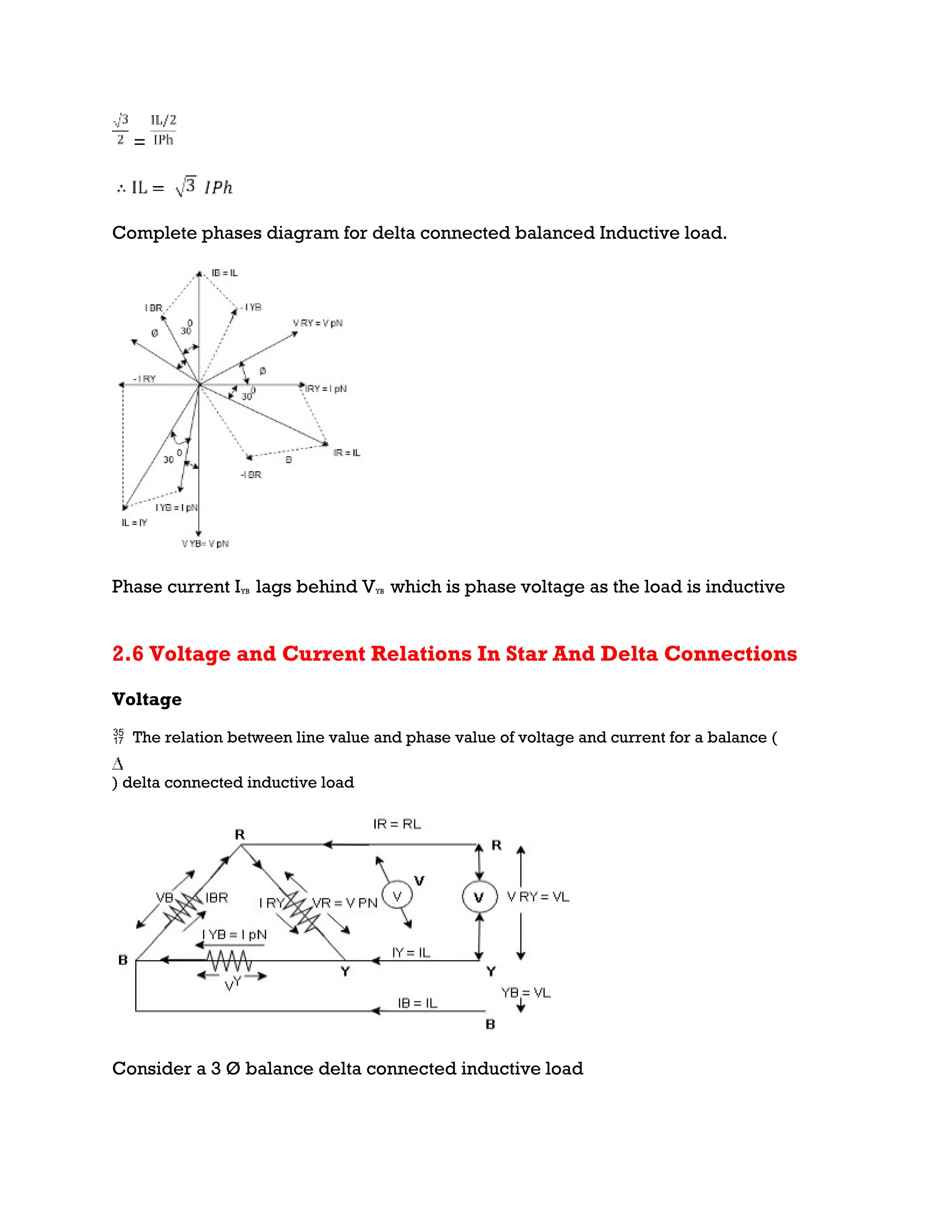
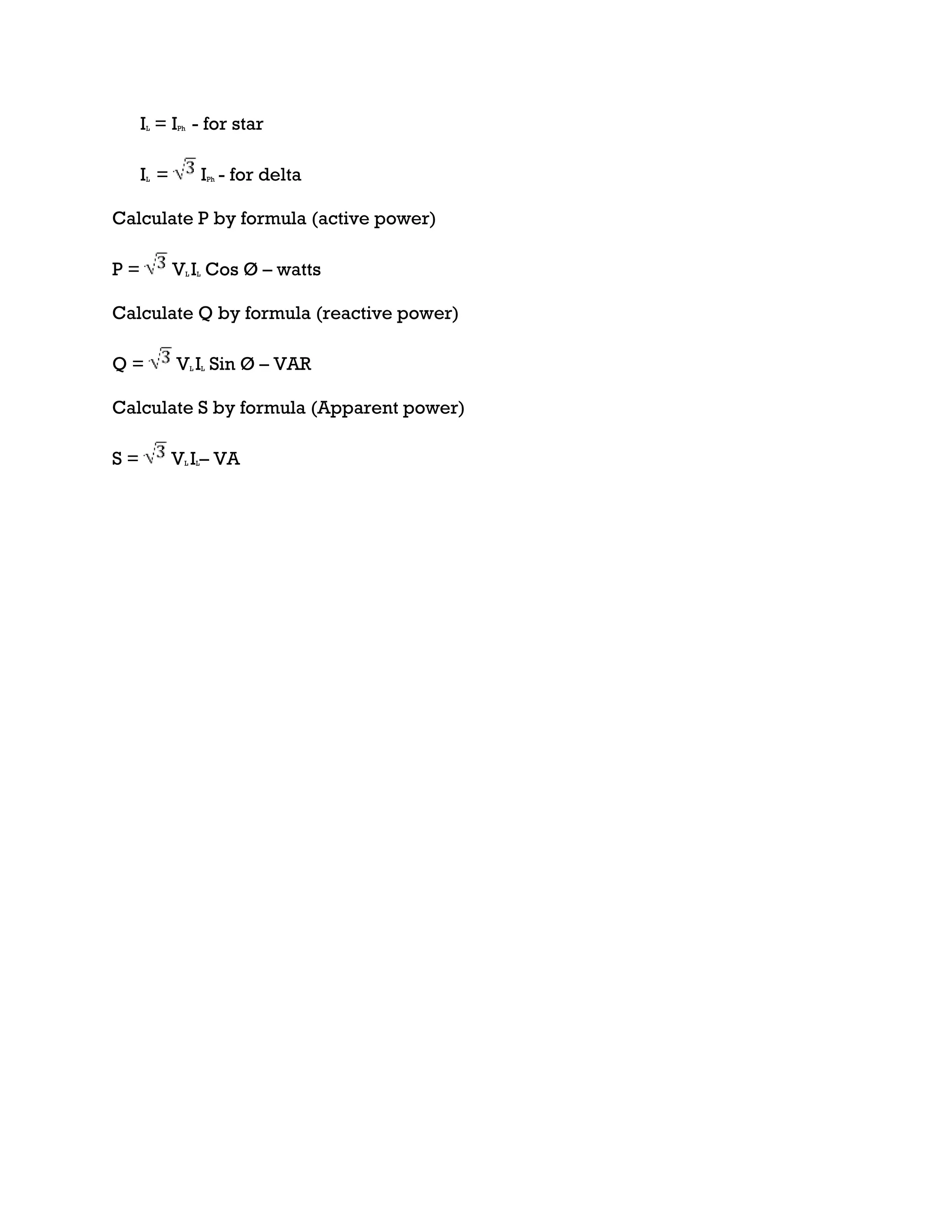
Voltage and current relations in star and delta connected inductive loads, providing formulas for calculating power and load behavior.


